
You also want an ePaper? Increase the reach of your titles
YUMPU automatically turns print PDFs into web optimized ePapers that Google loves.
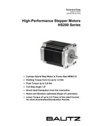
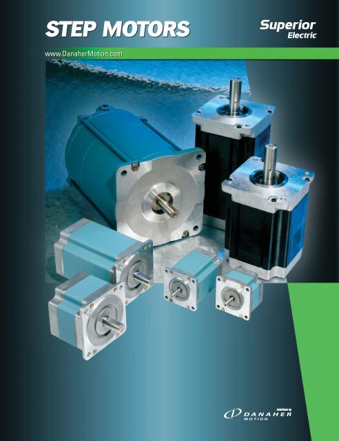
STEP MOTORS<br />
www.DanaherMotion.com
www.DanaherMotion.com • 704-588-5693<br />
2<br />
STEP MOTORS<br />
Danaher Motion<br />
and <strong>Superior</strong> <strong>Electric</strong><br />
<strong>Superior</strong> <strong>Electric</strong> is a Danaher Motion brand, and is<br />
recognized worldwide as the leading manufacturer of <strong>step</strong><br />
motor positioning systems. Over 40 years ago, <strong>Superior</strong><br />
<strong>Electric</strong> developed and patented their <strong>Superior</strong> <strong>step</strong> motor<br />
products.<br />
The <strong>Superior</strong> <strong>Electric</strong> family of automation products<br />
includes:<br />
• Step Motors<br />
• Step Motor Drives<br />
• Motion Controls<br />
• Synchronous Motors<br />
This catalog highlights the latest selection of high torque<br />
<strong>step</strong> <strong>motors</strong> from <strong>Superior</strong> <strong>Electric</strong>. Our new line of NEMA<br />
size 42 high torque <strong>motors</strong> complements and extends the<br />
range of our size 23 and 34 high torque <strong>motors</strong>. These high<br />
torque <strong>motors</strong> provide world-class performance, and<br />
represent the best value ever offered by <strong>Superior</strong> <strong>Electric</strong>.<br />
They provide twice the torque (and in some cases more than<br />
twice the torque) of older conventional <strong>step</strong> <strong>motors</strong>.<br />
Your partner in Motion Control<br />
Danaher Motion has extensive experience customizing<br />
<strong>motors</strong> to meet our customer’s specific design requirements.<br />
Our engineering staff will work with you to achieve your<br />
product performance goals. We provide motion control<br />
solutions for a wide variety markets and applications<br />
including:<br />
• Semiconductor manufacturing<br />
• Packaging<br />
• Printing<br />
• Industrial Automation<br />
• Testing and measurement<br />
Flexible manufacturing capabilities enable us to deliver<br />
specialized product quickly – helping you meet your<br />
development cycle objectives.<br />
Danaher Motion offers a comprehensive line of <strong>motors</strong>,<br />
drives, controls, and actuators designed to optimize the<br />
performance of motion control systems. These address a<br />
wide array of requirements, ranging from simple repetitive<br />
moves to complex multi-axis motion. On-going product<br />
development enables Danaher Motion to provide innovative,<br />
leading edge solutions to our customers.<br />
One of the best reasons to select a <strong>Superior</strong> <strong>Electric</strong> product<br />
is Danaher Motion's superior service and support. Our<br />
products are available globally through the industry’s most<br />
extensive and experienced distributor network. These<br />
trained distributors provide valuable technical assistance, in<br />
addition to fast delivery and service. A team of application<br />
engineers backs our distributor network. The combined<br />
experience of this support system ensures that our<br />
customers receive prompt, quality attention to their needs,<br />
no matter where they are located.<br />
Further assistance and support is provided on the web at<br />
www.DanaherMotion.com. Visitors to this site will find<br />
product information, technical specifications, and<br />
information on our distribution network. In addition,<br />
MOTIONEERING ® Motor Selection Software is available as a<br />
free download. This Windows ® based program makes it easy<br />
to select the best <strong>step</strong>per system for an application.
Table of Contents<br />
Introduction to Step Motors 4<br />
Typical Applications 4<br />
Features of a High Torque Step Motor 4<br />
Sizing and Selection Software 4<br />
Quick Selection Guide 5<br />
KM06 Series - NEMA 23 6-9<br />
KM09 Series - NEMA 34 10-13<br />
KM11 Series - NEMA 42 14-17<br />
MH172 Series - NEMA 66 18-19<br />
MX09 Series - NEMA 34 Hazardous Duty Motors 20<br />
MX11 Series - NEMA 42 Hazardous Duty Motors 21<br />
Encoders 22-23<br />
MOTIONEERING ® Application Software 24<br />
Application Assistance 24-28<br />
Technical Notes 29-31<br />
Connection Diagrams 31<br />
Options and Modifications 32<br />
Definitions 33-35<br />
How To Use This Catalog<br />
STEP STEP MOTORS MOTORS<br />
www.DanaherMotion.com<br />
www.DanaherMotion.com<br />
STEP MOTORS<br />
The quick selection guide on<br />
page 5 gives an overview of the<br />
entire product offering. Sections<br />
for each frame size are in order of<br />
increasing motor frame sizes.<br />
Each frame size section includes<br />
detailed motor specifications and<br />
speed torque curves of motor / drive<br />
system combinations. For easy<br />
comparison, the speed torque<br />
curves are arranged by drive voltage<br />
and motor length.<br />
Hazardous duty <strong>motors</strong>, add on<br />
options, and overall technical<br />
information are towards the back<br />
of the catalog.<br />
The table of contents at the left will<br />
help you find more information on<br />
each of our products.<br />
Additional information on all our<br />
products can be found by visiting<br />
our website at:<br />
www.DanaherMotion.com<br />
www.DanaherMotion.com • 815-226-2222<br />
3
www.DanaherMotion.com • 704-588-5693<br />
4<br />
STEP MOTORS<br />
Introduction<br />
To Step Motors<br />
<strong>Superior</strong> <strong>Electric</strong> <strong>step</strong> <strong>motors</strong> provide very precise, cost<br />
effective, motion control.<br />
<strong>Superior</strong> <strong>step</strong> <strong>motors</strong> inherently move in small, very<br />
precise, 1.8° increments (200 / revolution). This <strong>step</strong>ping<br />
action is simple to control and does not require<br />
complicated, expensive feedback devices. With micro<strong>step</strong>ping<br />
drives, each 1.8° <strong>step</strong> can be broken into even<br />
smaller increments. And, if position verification is<br />
required, <strong>motors</strong> are available with encoders.<br />
Due to their ease of use, simplified control needs and<br />
freedom from expensive feedback requirements, <strong>Superior</strong><br />
<strong>step</strong> <strong>motors</strong> are excellent alternatives to pneumatic,<br />
hydraulic and servo motor systems.<br />
Typical Applications<br />
• Automation and inspection<br />
• Conveyor transfer<br />
• Cut-to-length metal, plastic,<br />
fabric, etc.<br />
• Industrial HVAC<br />
• Material handling<br />
• Medical equipment<br />
• Office peripheral equipment<br />
• Packaging systems<br />
• Pick-and-place applications<br />
• Printing systems<br />
• Robotics<br />
• Semiconductor manufacturing<br />
High Torque Motor Construction<br />
Reliable High Temperature Insulation<br />
Special All Copper Windings<br />
Leads Locked in Place<br />
Robust Brushless Design<br />
Screw for Ground<br />
Connection<br />
Laminated Rotors with<br />
Permanent Magnets<br />
Rugged Square Frame<br />
Construction<br />
Long Life Double<br />
Shielded Ball Bearings<br />
Stainless<br />
Steel Shaft<br />
Sizing and Selection Software for<br />
<strong>Superior</strong> <strong>Electric</strong> Products<br />
Step motor systems are often used in high performance<br />
positioning systems. The correct motor and drive are<br />
equally important for the system to meet performance and<br />
cost goals. To select a motor and drive for a given<br />
situation requires an analysis of the load, mechanical<br />
system and desired cycle times or speeds.<br />
MOTIONEERING ® Software for<br />
<strong>Superior</strong> <strong>Electric</strong>, makes the selection<br />
process easy.<br />
MOTIONEERING ® is a menu driven, Windows ® -based<br />
program that automatically takes into<br />
account load, motor and drive<br />
parameters. A wide variety of<br />
mechanisms are accommodated<br />
including: lead screw, rack and<br />
pinion, conveyor (belt and pulley),<br />
nip rolls, and rotary, as well as direct<br />
data entry.<br />
MOTIONEERING ® provides a versatile environment for<br />
choosing the optimum system for your application, and is<br />
available free of charge.
Quick Selection Guide<br />
NEMA<br />
Frame<br />
23 6-9<br />
34 10-13<br />
42 14-17<br />
Page # Model<br />
Holding<br />
Torque<br />
oz-in (N-cm)<br />
Rotor Inertia<br />
oz-in-s 2<br />
(kg-cm 2 )<br />
KMO60 68 (48) 0.00154 (0.108)<br />
KMO61 170 (120) 0.0034 (0.24)<br />
KMO62 250 (177) 0.0056 (0.395)<br />
KMO63 350 (247) 0.0084 (0.593)<br />
KMO91 385 (272) 0.016 (1.13)<br />
KMO92 770 (544) 0.031 (2.19)<br />
KMO93 1,155 (816) 0.047 (3.32)<br />
KM111 1,450 (1,020) 0.078 (5.5)<br />
KM112 2,750 (1,940) 0.155 (10.9)<br />
KM113 3,750 (2,650 0.229 (16.2)<br />
66 18-19 MH172 5,330 (3,764) 0.870 (61.4)<br />
Holding Torque<br />
Relative Torque<br />
STEP MOTORS<br />
www.DanaherMotion.com • 704-588-5693<br />
5
www.DanaherMotion.com • 704-588-5693<br />
6<br />
STEP MOTORS<br />
KM06<br />
High Torque 60mm Frame Size<br />
(NEMA Size 23)<br />
Motor<br />
Frame<br />
KMO60<br />
KMO61<br />
KMO62<br />
KMO63<br />
Minimum Holding Torque<br />
Unipolar<br />
2Ø on<br />
oz-in<br />
(N-cm)<br />
54<br />
(38)<br />
128<br />
(90.4)<br />
188<br />
(133)<br />
263<br />
(186)<br />
Bipolar<br />
2Ø on<br />
oz-in<br />
(N-cm)<br />
68<br />
(48)<br />
170<br />
(120)<br />
250<br />
(177)<br />
350<br />
(247)<br />
Rotor<br />
Inertia<br />
oz-in-s2 (kg-cm2 )<br />
0.00154<br />
(0.108)<br />
0.0034<br />
(0.24)<br />
0.0056<br />
(0.395)<br />
0.0084<br />
(0.593)<br />
* Weight for motor with leads (add approximately 0.2 lbs for terminal box).<br />
Performance Envelope<br />
(see page 9 for detailed torque-speed curves)<br />
oz-in<br />
TORQUE<br />
[1.8° Steps/Sec]<br />
0<br />
350<br />
2000 4000 6000 8000 10000<br />
(N-cm)<br />
300<br />
212<br />
250 KM063<br />
177<br />
200<br />
150<br />
100<br />
KM062<br />
KM061<br />
50<br />
KM060<br />
35<br />
0<br />
0<br />
0 10 20 30 40 50<br />
Motor Speed (rps)<br />
• Up to 200% rated torque reserve capacity<br />
• ± 2% typical <strong>step</strong> accuracy<br />
• Terminal box, encoders, precision gearheads<br />
and rear shafts available<br />
• Available with four or six leads<br />
• Customized configurations available<br />
*Weight Maximum Shaft Load Minimum<br />
Net Ship Overhang Thrust<br />
Residual<br />
Torque<br />
lb<br />
(kg)<br />
1.03<br />
(0.47)<br />
1.6<br />
(0.73)<br />
2.3<br />
(1.04)<br />
3.2<br />
(1.45)<br />
lb<br />
(kg)<br />
1.1<br />
(0.050)<br />
1.7<br />
(0.77)<br />
2.5<br />
(1.1)<br />
3.4<br />
(1.5)<br />
lb<br />
(kg)<br />
15<br />
(6.8)<br />
15<br />
(6.8)<br />
15<br />
(6.8)<br />
15<br />
(6.8)<br />
lb<br />
(kg)<br />
25<br />
(11)<br />
25<br />
(11)<br />
25<br />
(11)<br />
25<br />
(11)<br />
141<br />
106<br />
71<br />
oz-in<br />
(N-cm)<br />
2.0<br />
(1.4)<br />
3.0<br />
(2.1)<br />
6.0<br />
(4.2)<br />
7.0<br />
(4.9)
KM06<br />
KM 06<br />
L leads<br />
T terminal box<br />
0 short stack<br />
1 single stack<br />
2 double stack<br />
3 triple stack<br />
Connections<br />
F four leads<br />
S six leads<br />
See next page for additional KM06 information<br />
XX total current<br />
STEP MOTORS<br />
E Rear shaft extension<br />
C2 200 line, six output encoder<br />
C4 400 line, six output encoder<br />
C5 500 line, six output encoder<br />
C12 1250 line, six output encoder<br />
4-CONNECTION STEP MOTORS<br />
Model Number Winding Specifications<br />
See Next page for options Voltage (VDC) Current (amperes) Resistance (ohms) Inductance (mH)<br />
KM � 060F02 3.8 1.1 3.6 16<br />
KM � 060F05 1.7 2.7 0.64 2.5<br />
KM � 060F08 1.1 4.0 0.28 1.0<br />
KM � 060F11 1.0 5.3 0.19 0.63<br />
KM � 061F02 5.2 1.1 4.9 30<br />
KM � 061F03 4.2 1.4 3.0 16<br />
KM � 061F05 2.3 2.7 0.85 4.6<br />
KM � 061F08 1.4 4.1 0.33 1.8<br />
KM � 061F11 1.2 5.4 0.23 1.1<br />
KM � 062F03 4.4 1.5 2.9 17<br />
KM � 062F05 3.1 2.5 1.3 7.1<br />
KM � 062F07 2.5 3.3 0.75 3.4<br />
KM � 062F08 2.0 4.1 0.49 2.5<br />
KM � 062F13 1.3 6.6 0.20 0.85<br />
KM � 063F03 6.1 1.5 4.1 24<br />
KM � 063F04 5.0 1.8 2.8 17<br />
KM � 063F07 3.4 3.3 1.0 6.2<br />
KM � 063F08 2.6 4.1 0.64 3.9<br />
KM � 063F13 1.9 6.6 0.28 1.5<br />
Model Number<br />
See Next page<br />
for options<br />
Voltage<br />
(VDC)<br />
6-CONNECTION STEP MOTORS<br />
Winding Specifications<br />
Unipolar Bipolar Series<br />
Current Resistance Inductance Voltage Current Resistance<br />
(amperes) (ohms) (mH) (VDC) (amperes) (ohms)<br />
Inductance<br />
(mH)<br />
KM � 060S03 2.9 1.5 1.9 4.0 4.0 1.0 3.9 16<br />
KM � 060S08 1.3 3.8 0.34 0.63 1.8 2.7 0.67 2.5<br />
KM � 061S02 6.4 1.0 6.4 18 9.0 0.70 13 70<br />
KM � 061S04 3.0 2.1 1.5 3.5 4.2 1.4 2.9 14<br />
KM � 061S08 1.7 3.8 0.46 1.1 2.4 2.7 0.92 4.4<br />
KM � 062S04 3.1 2.1 1.5 4.2 4.4 1.5 2.9 17<br />
KM � 062S06 2.8 3.0 0.94 2.5 3.9 2.1 1.9 10<br />
KM � 062S09 1.8 4.7 0.38 0.85 2.5 3.3 0.75 3.4<br />
KM � 063S04 4.3 2.1 2.0 6.0 6.0 1.5 4.0 24<br />
KM � 063S09 2.5 4.7 0.54 1.6 3.5 3.3 1.1 6.3<br />
www.DanaherMotion.com • 704-588-5693<br />
7
www.DanaherMotion.com • 704-588-5693<br />
8<br />
STEP MOTORS<br />
KM06: Motor Dimensions<br />
Add “E” to model number for double ended shaft. Example: M062-LS03E<br />
Encoder<br />
Terminal Box<br />
Add to Model Number:<br />
C2 200 lines per rev.<br />
C4 400 lines per rev.<br />
C5 500 lines per rev.<br />
C12 1250 lines per rev.<br />
Outputs: A, B, Index,<br />
A, B, Index,<br />
Differential Line Drivers supplied<br />
Example: KML063S09C5<br />
Change to Model Number:<br />
For encoder specifications see pages 22-23<br />
Example: KMT063S09 (triple stack, terminal<br />
box, six leads, 4.7 amp winding)
KMO6<br />
KM060<br />
KM061<br />
KM062<br />
KM063<br />
24 V Bipolar - Full Step<br />
24 volt data measured with<br />
SS2000MD4 drive.<br />
KM� 060F02 - 1.0 A peak KM� 060F05 - 1.0 A peak<br />
KM� 060F05 - 2.5 A peak KM� 060F11 - 3.5 A peak<br />
KM� 061F02 - 1.0 A peak<br />
KM� 061F08 - 3.5 A peak<br />
TO RQUE - oz i n<br />
[1.8 ° Steps/Sec]<br />
0<br />
250<br />
2000 4000 6000 8000 10000<br />
(Ncm)<br />
225 159<br />
200 141<br />
175 124<br />
150 106<br />
125 88<br />
100 71<br />
75 53<br />
50 35<br />
25 18<br />
0 0<br />
0 10 20 30 40 50<br />
Motor Speed (rps)<br />
KM� 062F03 - 1.0 A peak KM� 062F05 - 2.5 A peak<br />
KM� 062F08 - 3.5 A peak<br />
350<br />
300 212<br />
250 177<br />
200 141<br />
150 106<br />
100 71<br />
50 35<br />
0 0<br />
KM� 063F03 - 1.0 A peak KM� 063F07 - 3.0 A peak<br />
KM� 063F13 - 3.5 A peak<br />
36 V Bipolar - Full Step<br />
36 volt data measured with<br />
SS2000MD4 drive.<br />
KM� 060F05 - 2.5 A peak KM� 060F08 - 3.5 A peak<br />
KM� 061F04 - 1.0 A peak KM� 061F05 - 2.5 A peak<br />
KM� 061F08 - 3.5 A peak<br />
KM� 061F08 - 2.5 A peak<br />
TO RQUE - oz i n<br />
[1.8 ° Steps/Sec]<br />
0<br />
250<br />
2000 4000 6000 8000 10000<br />
(Ncm)<br />
225 159<br />
200 141<br />
175 124<br />
150 106<br />
125 88<br />
100 71<br />
75 53<br />
50 35<br />
25 18<br />
0 0<br />
0 10 20 30 40 50<br />
Motor Speed (rps)<br />
KM� 062F05 - 2.5 A peak KM� 062F08 - 2.5 A peak<br />
KM� 062F08 - 3.5 A peak KM� 062F13 - 3.5 A peak<br />
350<br />
300 212<br />
250 177<br />
200 141<br />
150 106<br />
100 71<br />
50 35<br />
0 0<br />
KM� 063F04 - 2.0 A peak KM� 063F08 - 2.5 A peak<br />
KM� 063F07 - 3.0 A peak KM� 063F13 - 3.5 A peak<br />
TO RQUE - oz i n<br />
STEP MOTORS<br />
72 V Bipolar - Micro<strong>step</strong><br />
72 volt data measured with<br />
MD808 drive<br />
• The curves do not show system<br />
resonances which will vary with<br />
system mechanical parameters.<br />
• Duty cycle is dependent on torque,<br />
speed, drive parameters, and heat<br />
sink conditions. Maximum case<br />
temperature is 100°C.<br />
KM� 061F05 - 3.0 A peak KM� 061F08 - 6.0 A peak<br />
KM� 061F11 - 7.5 A peak<br />
[1.8 ° Steps/Sec]<br />
0<br />
250<br />
2000 4000 6000 8000 10000<br />
(Ncm)<br />
225 159<br />
200 141<br />
175 124<br />
150 106<br />
125 88<br />
100 71<br />
75 53<br />
50 35<br />
25 18<br />
0 0<br />
0 10 20 30 40 50<br />
Motor Speed (rps)<br />
KM� 062F07 - 4.0 A peak KM� 062F13 - 8.0 A peak<br />
350<br />
300 212<br />
250 177<br />
200 141<br />
150 106<br />
100 71<br />
50 35<br />
0 0<br />
KM� 063F07 - 4.0 A peak KM� 063F13 - 8.0 A peak<br />
www.DanaherMotion.com • 704-588-5693<br />
9
www.DanaherMotion.com • 704-588-5693<br />
10<br />
STEP MOTORS<br />
KM09<br />
High Torque 90mm Frame Size (NEMA Size 34)<br />
Motor<br />
Frame<br />
KMO91<br />
KMO92<br />
KMO93<br />
Minimum Holding Torque<br />
Unipolar<br />
2Ø on<br />
oz-in<br />
(N-cm)<br />
305<br />
(215)<br />
610<br />
(431)<br />
915<br />
(646)<br />
* Weight for motor with leads.<br />
Bipolar<br />
2Ø on<br />
oz-in<br />
(N-cm)<br />
385<br />
(272)<br />
770<br />
(544)<br />
1155<br />
(816)<br />
Rotor<br />
Inertia<br />
oz-in-s2 (kg-cm2 )<br />
.016<br />
(1.13)<br />
.031<br />
(2.19)<br />
.047<br />
(3.32)<br />
Performance Envelope<br />
(see page 13 for detailed torque-speed curves)<br />
• Up to 200% rated torque reserve capacity<br />
• ± 2% typical <strong>step</strong> accuracy<br />
• Standard terminal box, encoders, and precision<br />
gearheads available<br />
• Available with four or six leads<br />
• Customized configurations available<br />
*Weight Maximum Shaft Load Minimum<br />
Net Ship Overhang Thrust<br />
Residual<br />
Torque<br />
lb<br />
(kg)<br />
3.8<br />
(1.73)<br />
6.2<br />
(2.82)<br />
8.7<br />
(3.95)<br />
lb<br />
(kg)<br />
4.0<br />
(1.81)<br />
6.4<br />
(2.90)<br />
8.9<br />
(4.03)<br />
lb<br />
(kg)<br />
25<br />
(11)<br />
25<br />
(11)<br />
25<br />
(11)<br />
lb<br />
(kg)<br />
50<br />
(23)<br />
50<br />
(23)<br />
50<br />
(23)<br />
oz-in<br />
(N-cm)<br />
10<br />
(7.1)<br />
15<br />
(11)<br />
23<br />
(16)
KM09<br />
KM 09<br />
L leads<br />
T terminal box<br />
1 single stack<br />
2 double stack<br />
3 triple stack<br />
Connections<br />
F four leads<br />
S six leads<br />
See next page for additional KM09 information<br />
XX total current<br />
STEP MOTORS<br />
E Rear shaft extension<br />
C2 200 line, six output encoder<br />
C4 400 line, six output encoder<br />
C5 500 line, six output encoder<br />
C12 1250 line, six output encoder<br />
4-CONNECTION STEP MOTORS<br />
Model Number Winding Specifications<br />
See Next page for options Voltage (VDC) Current (amperes) Resistance (ohms) Inductance (mH)<br />
KM � 091F05 3.0 2.7 1.1 11<br />
KM � 091F07 2.5 3.3 0.76 7.5<br />
KM � 091F13 1.3 6.6 0.19 1.9<br />
KM � 092F07 3.5 3.3 1.1 11<br />
KM � 092F13 1.7 6.5 0.27 2.9<br />
KM � 093F07 4.9 3.4 1.4 18<br />
KM � 093F08 4.0 4.0 0.99 13<br />
KM � 093F10 3.2 5.1 0.63 8.3<br />
KM � 093F14 2.5 6.8 0.36 4.5<br />
Model Number<br />
See Next page<br />
for options<br />
Voltage<br />
(VDC)<br />
6-CONNECTION STEP MOTORS<br />
Winding Specifications<br />
Unipolar Bipolar Series<br />
Current Resistance Inductance Voltage Current Resistance<br />
(amperes) (ohms) (mH) (VDC) (amperes) (ohms)<br />
Inductance<br />
(mH)<br />
KM � 091S02 9.3 1.0 9.3 47 13 0.70 19 190<br />
KM � 091S06 2.9 3.1 0.94 4.7 4.1 2.2 1.9 19<br />
KM � 091S08 2.1 3.8 0.55 2.9 2.9 2.7 1.1 11<br />
KM � 091S09 1.8 4.7 0.38 1.9 2.5 3.3 0.76 7.5<br />
KM � 092S09 2.5 4.6 0.54 2.8 3.4 3.2 1.1 11<br />
KM � 093S07 4.4 3.5 1.3 8.3 6.2 2.5 2.5 3.3<br />
KM � 093S10 3.5 4.8 0.72 4.5 4.8 3.4 1.4 18<br />
www.DanaherMotion.com • 704-588-5693<br />
11
www.DanaherMotion.com • 704-588-5693<br />
12<br />
STEP MOTORS<br />
KM09: Motor Dimensions<br />
Add “E” to model number for double ended shaft. Example: KML092F07E<br />
Encoder<br />
C2, C4, C500 Encoders<br />
C12 Encoder<br />
Terminal Box<br />
Terminal Box<br />
w/Encoder<br />
Add to Model Number:<br />
C2 200 lines per rev.<br />
C4 400 lines per rev.<br />
C5 500 lines per rev.<br />
C12 1250 lines per rev.<br />
Outputs: A, B, Index,<br />
Change to Model Number:<br />
Example: KMT093S07 (triple stack, terminal box,<br />
six leads, 3.5 amp winding)<br />
Change to Model Number:<br />
A, B, Index,<br />
Differential Line Drivers supplied<br />
Example: KML093S07C5 (triple stack,<br />
leaded, six leads, 3.5 amp winding)<br />
For encoder specification see page 22-23<br />
Example: KMT092F07C12 (double stack, terminal box,<br />
four leads, 3.3 amp winding,<br />
C12 encoder)
KM09<br />
KM091<br />
KM092<br />
KM093<br />
36 V Bipolar - Full Step<br />
36 volt data measured with<br />
the SS2000MD4 Modular<br />
Drive.<br />
400<br />
350<br />
300<br />
250<br />
200<br />
150<br />
100<br />
50<br />
0<br />
KM� 091F05 - 2.5 A peak KM� 091F13 - 2.5 A peak<br />
KM� 091F13 - 3.5 A peak<br />
800<br />
700<br />
600<br />
500<br />
400<br />
300<br />
200<br />
100<br />
0<br />
KM� 092F07 - 2.5 A peak KM� 092F07 - 3.5 A peak<br />
KM� 092F13 - 2.5 A peak KM� 092F13 - 3.5 A peak<br />
1200<br />
1000<br />
800<br />
600<br />
400<br />
200<br />
0 0<br />
KM� 093F07 - 2.5 A peak KM� 093F10 - 2.5 A peak<br />
KM� 093F14 - 3.5 A peak<br />
247<br />
212<br />
177<br />
141<br />
106<br />
71<br />
35<br />
0<br />
494<br />
424<br />
353<br />
282<br />
212<br />
141<br />
71<br />
0<br />
706<br />
565<br />
424<br />
282<br />
141<br />
72 V Bipolar - Micro<strong>step</strong><br />
72 volt data measured with<br />
MD808 Modular Drive<br />
400<br />
350<br />
300<br />
250<br />
200<br />
150<br />
100<br />
50<br />
0<br />
KM� 091F07 - 4.0 A peak KM� 091F13 - 4.0 A peak<br />
KM� 091F13 - 8.0 A peak<br />
800<br />
700<br />
600<br />
500<br />
400<br />
300<br />
200<br />
100<br />
0<br />
247<br />
212<br />
177<br />
141<br />
106<br />
71<br />
35<br />
0<br />
494<br />
424<br />
353<br />
282<br />
212<br />
141<br />
KM� 092F07 - 4.0 A peak KM� 092F013 - 4.0 A peak<br />
KM� 092F13 - 8.0 A peak<br />
1200<br />
1000<br />
800<br />
600<br />
400<br />
200<br />
0 0<br />
KM� 093F07 - 4.0 A peak KM� 093F10 - 7.0 A peak<br />
KM� 093F14 - 8.0 A peak<br />
• The curves do not show system resonances which will vary with system mechanical parameters.<br />
• Duty cycle is dependent on torque, speed, drive parameters, and heat sink conditions.<br />
Maximum case temperature is 100°C.<br />
71<br />
0<br />
706<br />
565<br />
424<br />
282<br />
141<br />
400<br />
350<br />
300<br />
250<br />
200<br />
150<br />
100<br />
50<br />
0<br />
800<br />
700<br />
600<br />
500<br />
400<br />
300<br />
200<br />
100<br />
0<br />
1000<br />
600<br />
400<br />
200<br />
STEP MOTORS<br />
170 V Bipolar - Micro<strong>step</strong><br />
170 volt data measured with<br />
SS2000D3, D3i, D6, or D6i<br />
Packaged Drive<br />
KM� 091F05 - 3.0 A peak KM� 091F07 - 3.0 A peak<br />
KM� 092F07 - 3.0 A peak KM� 092F07 - 4.0 A peak<br />
KM� 092F13 - 3.0 A peak KM� 092F13 - 6.0 A peak<br />
1200<br />
800<br />
0 0<br />
KM� 093F07 - 3.0 A peak KM� 093F10 - 6.0 A peak<br />
KM� 093F14 - 3.0 A peak KM� 093F14 - 6.0 A peak<br />
247<br />
212<br />
177<br />
141<br />
106<br />
71<br />
35<br />
0<br />
494<br />
424<br />
353<br />
282<br />
212<br />
141<br />
71<br />
0<br />
706<br />
565<br />
424<br />
282<br />
141<br />
www.DanaherMotion.com • 704-588-5693<br />
13
www.DanaherMotion.com • 704-588-5693<br />
14<br />
STEP MOTORS<br />
KM11<br />
High Torque 170mm Frame Size (NEMA Size 42)<br />
Motor<br />
Frame<br />
KML111<br />
KML112<br />
KML113<br />
* Weight for motor with leads.<br />
Minimum Holding Torque<br />
Unipolar<br />
2Ø on<br />
oz-in<br />
(N-cm)<br />
1,030<br />
(730)<br />
1,950<br />
(1,380)<br />
2,650<br />
(1,870)<br />
Bipolar<br />
2Ø on<br />
oz-in<br />
(N-cm)<br />
1,450<br />
(1,020)<br />
2,750<br />
(1,940)<br />
3,750<br />
(2,650)<br />
Rotor<br />
Inertia<br />
oz-in-s2 (kg-cm2 )<br />
0.078<br />
(5.5)<br />
0.155<br />
(10.9)<br />
0.229<br />
(16.2)<br />
Performance Envelope<br />
(see page 17 for detailed torque-speed curves)<br />
3000<br />
2500<br />
2000<br />
1500<br />
1000<br />
500<br />
KM113<br />
KM112<br />
KM111<br />
*Weight Maximum Shaft Load Minimum<br />
Net Ship Overhang Thrust<br />
Residual<br />
Torque<br />
lb<br />
(kg)<br />
11.0<br />
(5.0)<br />
18.4<br />
(8.3)<br />
25.7<br />
(11.7)<br />
• Up to 200% rated torque reserve capacity<br />
• ±5% typical <strong>step</strong> accuracy<br />
• Standard terminal box, encoders, and precision<br />
gearheads available<br />
• Available with four, six, or eight leads<br />
• Customized configurations available<br />
lb<br />
(kg)<br />
12.2<br />
(5.5)<br />
19.6<br />
(8.9)<br />
26.9<br />
(12.2)<br />
lb<br />
(kg)<br />
75<br />
(34.0)<br />
75<br />
(34.0)<br />
75<br />
(34.0)<br />
lb<br />
(kg)<br />
130<br />
(59.0)<br />
160<br />
(72.6)<br />
160<br />
(72.6)<br />
oz-in<br />
(N-cm)<br />
42<br />
(30)<br />
84<br />
(59)<br />
106<br />
(75)
KM11<br />
KM 11<br />
L leads<br />
T terminal box<br />
STEP MOTORS<br />
4-CONNECTION STEP MOTORS<br />
Model Number Winding Specifications<br />
See Next page for options Voltage (VDC) Current (amperes) Resistance (ohms) Inductance (mH)<br />
KM � 111F05 6.3 2.7 2.33 40.4<br />
KM � 111F09 4.1 4.4 0.93 15.8<br />
KM � 111F11 3.2 5.5 0.58 10.1<br />
KM � 111F17 2.0 8.7 0.23 3.9<br />
KM � 111F21 1.7 10.7 0.16 2.8<br />
KM � 112F06 7.7 3.2 2.41 51.1<br />
KM � 112F08 6.0 4.0 1.51 31.2<br />
KM � 112F10 5.0 4.9 1.02 22<br />
KM � 112F13 3.2 7.9 0.41 8.4<br />
KM � 112F16 3.8 6.4 0.6 12.8<br />
KM � 112F20 2.5 9.9 0.25 5.5<br />
KM � 112F32 1.6 15.8 0.1 2.1<br />
KM � 113F06 10.2 3.1 3.29 78.5<br />
KM � 113F08 7.9 4.0 1.98 44.2<br />
KM � 113F10 6.5 4.9 1.32 30.7<br />
KM � 113F12 5.1 6.2 0.82 19.6<br />
KM � 113F16 4.0 8.0 0.5 11<br />
KM � 113F20 3.3 9.9 0.33 7.7<br />
KM � 113F31 2.2 15.4 0.14 3.2<br />
Model Number<br />
See Next page<br />
for options<br />
1 single stack<br />
2 double stack<br />
3 triple stack<br />
Voltage<br />
(VDC)<br />
Connections<br />
F four leads<br />
S six leads<br />
E eight leads<br />
XX total current<br />
E Rear shaft extension<br />
C2 200 line, six output encoder<br />
C4 400 line, six output encoder<br />
C5 500 line, six output encoder<br />
C12 1250 line, six output encoder<br />
8-CONNECTION STEP MOTORS<br />
Winding Specifications<br />
Bipolar Series Bipolar Parallel<br />
Current Resistance Inductance Voltage Current Resistance<br />
(amperes) (ohms) (mH) (VDC) (amperes) (ohms)<br />
Inductance<br />
(mH)<br />
KM � 111E08 6.3 2.7 2.33 40.4 3.2 5.5 0.58 10.1<br />
KM � 111E12 4.1 4.4 0.93 15.8 2.0 8.7 0.23 3.9<br />
KM � 111E15 3.3 5.3 0.63 11.1 1.7 10.7 0.16 2.8<br />
KM � 112E09 7.7 3.2 2.41 51.1 3.8 6.4 0.6 12.8<br />
KM � 112E11 6.0 4.0 1.51 31.2 3.1 8.1 0.38 7.8<br />
KM � 112E14 5.0 4.9 1.02 22 2.5 9.9 0.25 5.5<br />
KM � 112E22 3.2 7.9 0.41 8.4 1.6 15.8 0.1 2.1<br />
KM � 113E09 10.2 3.1 3.29 78.5 5.1 6.2 0.82 19.6<br />
KM � 113E11 7.9 4.0 1.98 44.2 4.0 8.0 0.5 11<br />
KM � 113E14 6.5 4.9 1.32 30.7 3.3 9.9 0.33 7.7<br />
KM � 113E22 4.2 7.7 0.55 13 2.2 15.4 0.14 3.2<br />
www.DanaherMotion.com • 704-588-5693<br />
15
www.DanaherMotion.com • 704-588-5693<br />
16<br />
4 MTG HOLES<br />
ø.328 [8.33]<br />
STEP MOTORS<br />
KM11: Motor Dimensions<br />
Encoder<br />
4.325<br />
[109.85]<br />
3.500<br />
[88.90]<br />
C2, C4, C500 Encoders<br />
C12 Encoder<br />
Terminal Box<br />
1.25 ± .06<br />
[31.75 ± 1.52]<br />
ø .5000 [12.700]<br />
.4995 [12.687]<br />
DOUBLE ENDED SHAFT<br />
MAX. LENGTH<br />
KM111 SERIES 3.89 [98.81]<br />
KM112 SERIES 5.91 [150.1]<br />
KM113 SERIES 7.92 [201.2]<br />
MAX. LENGTH<br />
KM111 SERIES 4.89 [124.2]<br />
KM112 SERIES 6.91 [175.5]<br />
KM113 SERIES 8.92 [126.6]<br />
MAX. LENGTH<br />
KM111 SERIES 5.39 [136.9]<br />
KM112 SERIES 7.41 [188.2]<br />
KM113 SERIES 9.42 [239.3]<br />
MAX. LENGTH<br />
KM111 SERIES 5.20 [132.1]<br />
KM112 SERIES 7.22 [183.4]<br />
KM113 SERIES 9.23 [234.4]<br />
.48 [12.19]<br />
12" [305] MIN<br />
LEAD LENGTH<br />
2<br />
#18 AWG [ 0.96 mm ]<br />
.06 [1.52]<br />
2.19 [55.63]<br />
1.375 [34.93]<br />
ø .7500<br />
.7495<br />
[19.050]<br />
[19.037]<br />
.830<br />
.813<br />
[21.08]<br />
[20.65]<br />
ø 2.186 ± .002<br />
[ø 55.524 ± 0.051]<br />
Add to Model Number:<br />
C2 200 lines per rev.<br />
C4 400 lines per rev.<br />
C5 500 lines per rev.<br />
C12 1250 lines per rev.<br />
Outputs: A, B, Index,<br />
Change to Model Number:<br />
A, B, Index,<br />
Differential Line Drivers supplied<br />
Example: KML113F08C5<br />
For encoder specification see pages 22-23<br />
.1875<br />
.1855<br />
[4.763]<br />
[4.712]<br />
Example: KMT113F08 (triple stack, terminal box,<br />
four leads, 4 amp winding)
KM11<br />
KM111<br />
KM112<br />
KM113<br />
72 V Bipolar - Micro<strong>step</strong><br />
72 volt data measured with<br />
MD808 Modular Drive<br />
1400<br />
1200<br />
1000<br />
800<br />
600<br />
400<br />
250<br />
0<br />
2500<br />
2000<br />
1500<br />
1000<br />
500<br />
0<br />
3500<br />
3000<br />
2500<br />
2000<br />
KM� 111F09 - 5.7 A peak - or KM� 111E12 series<br />
KM� 111F11 - 7.1 A peak - or KM� 111E08 parallel<br />
KM� 111F11 - 5.7 A peak - or KM� 111E08 parallel<br />
KM� 112F10 - 7.1 A peak - or KM� 112E14 series<br />
KM� 112F16 - 7.1 A peak - or KM� 112E22 series<br />
1500<br />
1000<br />
500<br />
0<br />
KM� 113F10 - 7.1 A peak - or KM� 113E14 series<br />
KM� 113F16 - 7.1 A peak - or KM� 113E11 parallel<br />
170 V Bipolar - Micro<strong>step</strong><br />
170 volt data measured with<br />
SS2000D3, D3i, D6, or D6i<br />
Packaged Drive<br />
1400<br />
1200<br />
1000<br />
800<br />
600<br />
400<br />
250<br />
2500<br />
2000<br />
1500<br />
1000<br />
500<br />
0<br />
0<br />
3500<br />
3000<br />
2500<br />
2000<br />
1500<br />
1000<br />
500<br />
0<br />
KM� 111F09 - 6 A peak - or KM� 111E12 series<br />
KM� 111F05 - 3 A peak - or KM� 111E08 series<br />
KM� 111F09 - 4 A peak - or KM� 111E12 series<br />
KM� 112F10 - 6 A peak - or KM� 112E14 series<br />
KM� 112F08 - 4 A peak - or KM� 112E11 series<br />
KM� 112F13 - 6 A peak - or KM� 112E09 parallel<br />
KM� 113F10 - 6 A peak - or KM� 113E14 series<br />
KM� 113F12 - 6 A peak - or KM� 113E09 parallel<br />
KM� 113F20 - 8 A peak - or KM� 113E14 parallel<br />
• The curves do not show system resonances which will vary with system mechanical parameters.<br />
• Duty cycle is dependent on torque, speed, drive parameters, and heat sink conditions.<br />
Maximum case temperature is 100°C.<br />
1400<br />
1200<br />
1000<br />
800<br />
600<br />
400<br />
250<br />
0<br />
2500<br />
2000<br />
1500<br />
1000<br />
3500<br />
3000<br />
2500<br />
2000<br />
500<br />
500<br />
1500<br />
1000<br />
0<br />
0<br />
STEP MOTORS<br />
340 V Bipolar - Micro<strong>step</strong><br />
KM� 111F05 - 3.9 A peak - or KM� 111E08 series<br />
KM� 111F05 - 3 A peak - or KM� 111E08 series<br />
KM� 112F08 - 6 A peak - or KM� 112E11 series<br />
KM� 112F06 - 3.9 A peak - or KM� 112E09 series<br />
KM� 112F10 - 5 A peak - or KM� 112E14 series<br />
KM� 112F08 - 3.9 A peak - or KM� 112E11 series<br />
KM� 113F06 - 3.9 A peak - or KM� 113E09 series<br />
KM� 113F10 - 6 A peak - or KM� 113E14 series<br />
KM� 113F12 - 6 A peak - or KM� 113E09 parallel<br />
KM� 113F10 - 3.9 A peak - or KM� 113E14 series<br />
www.DanaherMotion.com • 704-588-5693<br />
17
www.DanaherMotion.com • 704-588-5693<br />
18<br />
STEP MOTORS<br />
MH172<br />
High Torque 170mm Frame Size (NEMA Size 66)<br />
MH172 Specifications<br />
Motor<br />
Frame<br />
MH172<br />
Minimum<br />
Holding Torque<br />
Bipolar 2Ø On<br />
oz-in<br />
(N-cm)<br />
5,330<br />
(3,764)<br />
* Weight for motor with leads.<br />
Rotor<br />
Inertia<br />
oz-in-s2 (kg-cm2 )<br />
0.870<br />
(61.4)<br />
Performance Envelope<br />
(see page 19 for detailed torque-speed curves)<br />
[1.8° Steps/Sec]<br />
0 2000 4000 6000 8000 10000<br />
353<br />
0<br />
0 10 20 30 40 50<br />
Motor Speed (rps)<br />
0<br />
5000<br />
4500<br />
3176<br />
4000 2824<br />
3500<br />
2471<br />
3000 2118<br />
2500<br />
1764<br />
2000<br />
1412<br />
1500 170 V 340 V<br />
1059<br />
1000 706<br />
500<br />
• Can withstand up to 2-1/2 time rated<br />
current (instantaneous)<br />
• ± 5% typical <strong>step</strong> accuracy<br />
• Available with eight connections<br />
• Class F insulation system<br />
• Standard keyway<br />
*Weight Maximum Shaft Load Minimum<br />
Net Ship Overhang Thrust<br />
Residual<br />
Torque<br />
lb<br />
(kg)<br />
53<br />
(24)<br />
lb<br />
(kg)<br />
62<br />
(28)<br />
MH 172 FD 8030<br />
lb<br />
(kg)<br />
100<br />
(45.4)<br />
E Rear shaft extension<br />
C2 200 line, six output encoder<br />
C4 400 line, six output encoder<br />
C5 500 line, six output encoder<br />
lb<br />
(kg)<br />
150<br />
(68)<br />
oz-in<br />
(N-cm)<br />
50<br />
(35)
MH172<br />
Motor Dimensions*<br />
* Encoder if applicable, fits inside terminal box<br />
MH172<br />
TORQUE -ozin<br />
170 V Bipolar - Micro<strong>step</strong> 340 V Bipolar - Micro<strong>step</strong><br />
[1.8° Steps/Sec]<br />
0<br />
5000<br />
2000 4000 6000 8000 10000<br />
(Ncm)<br />
4500 3177<br />
4000 2824<br />
3500 2471<br />
3000 2118<br />
2500 1765<br />
2000 1412<br />
1500 1059<br />
1000 706<br />
500 353<br />
0<br />
0 10 20 30 40<br />
0<br />
50<br />
Motor Speed (rps)<br />
• The curves do not show system resonances which will vary with system mechanical parameters.<br />
• Duty cycle is dependent on torque, speed, drive parameters, and heat sink conditions.<br />
Maximum case temperature is 100°C.<br />
TORQUE -ozin<br />
[1.8° Steps/Sec]<br />
0<br />
5000<br />
2000 4000 6000 8000 10000<br />
(Ncm)<br />
4500 3177<br />
4000 2824<br />
3500 2471<br />
3000 2118<br />
2500 1765<br />
2000 1412<br />
1500 1059<br />
1000 706<br />
500 353<br />
0<br />
0<br />
10 20 30 40 50<br />
Motor Speed (rps)<br />
MH172-FD-8030 series - 12.0 A peak MH172-FD-8030 parallel -12.0 A peak MH172-FD-8030 series - 12.0 A peak MH172-FD-8030 parallel - 12.0 A peak<br />
STEP MOTORS<br />
8-CONNECTION STEP MOTORS<br />
Model Number<br />
Bipolar Series<br />
Winding Specifications<br />
Bipolar Parallel<br />
See below<br />
Voltage Current Resistance Inductance Voltage Current Resistance Inductance<br />
for options<br />
(VDC) (amperes) (ohms) (mH) (VDC) (amperes) (ohms) (mH)<br />
MH172-FD-8030 3.25 10.6 0.31 8.5 1.6 21 0.077 2.1<br />
www.DanaherMotion.com • 704-588-5693<br />
19
www.DanaherMotion.com • 704-588-5693<br />
20<br />
STEP MOTORS<br />
MX09<br />
Hazardous Duty 90mm Frame Size<br />
4-CONNECTION STEP MOTORS<br />
*Model Number<br />
Min. Holding<br />
Torque Bipolar<br />
2Ø on<br />
oz-in (N-cm)<br />
Winding Specifications Rotor Inertia<br />
oz-in-s2 (kg-cm2 Voltage<br />
(VDC)<br />
Current Resistance<br />
(amperes) (ohms)<br />
Inductance<br />
(mH)<br />
)<br />
MX91-FF-206U<br />
MX91-FF-402U<br />
MX91-FF-403U<br />
180<br />
(127)<br />
3.0<br />
2.9<br />
1.1<br />
3.0<br />
4.0<br />
6.0<br />
1.0<br />
0.72<br />
0.18<br />
10<br />
6.0<br />
1.5<br />
0.0095<br />
(0.67)<br />
MX92-FF-206U 370 4.0 4.0 1.0 11 0.0174<br />
MX92-FF-401U (261) 1.9 7.0 0.28 2.8 (1.23)<br />
MX93-FF-206U<br />
MX93-FF-401U<br />
MX93-FF-402U<br />
550<br />
(388)<br />
3.9<br />
3.2<br />
1.1<br />
4.0<br />
5.0<br />
7.0<br />
0.90<br />
0.65<br />
0.16<br />
13<br />
8.0<br />
2.0<br />
0.0265<br />
(1.87)<br />
* Change U to EU for double-ended shaft<br />
NOTE: Refer to MOTIONEERING ® for speed torque curves<br />
• Up to 150% rated torque reserve capacity<br />
• ± 3% typical <strong>step</strong> accuracy<br />
• Hazardous Duty:<br />
UL Class 1, Division 1, Group D<br />
Weight -Ship<br />
lb (kg)<br />
6<br />
(2.7)<br />
9<br />
(4.1)<br />
11<br />
(5)<br />
Maximum Shaft Load Min. Residual<br />
Overhang<br />
lb (kg)<br />
25<br />
(11)<br />
25<br />
(11)<br />
25<br />
(11)<br />
Thrust<br />
lb (kg)<br />
50<br />
(23)<br />
50<br />
(23)<br />
50<br />
(23)<br />
Torque<br />
oz-in (N-cm)<br />
2.0<br />
(1.4)<br />
4.0<br />
(2.8)<br />
7.0<br />
(4.9)
MX11<br />
Hazardous Duty 110mm Frame Size<br />
* Change U to EU for double-ended shaft<br />
NOTE: Refer to MOTIONEERING ® for speed torque curves<br />
Dimensions<br />
STEP MOTORS<br />
• Up to 200% rated torque reserve capacity<br />
• ± 5% typical <strong>step</strong> accuracy<br />
• Hazardous Duty:<br />
UL Class 1, Division 1, Group D<br />
4-CONNECTION STEP MOTORS<br />
*Model Number<br />
Min. Holding<br />
Torque Bipolar<br />
2Ø on<br />
oz-in (N-cm)<br />
Winding Specifications Rotor Inertia<br />
oz-in-s2 (kg-cm2 Voltage<br />
(VDC)<br />
Current Resistance<br />
(amperes) (ohms)<br />
Inductance<br />
(mH)<br />
)<br />
Weight -<br />
Ship<br />
lb (kg)<br />
Maximum Shaft Load<br />
Overhang Thrust<br />
lb (kg) lb (kg)<br />
Min. Residual<br />
Torque<br />
oz-in (N-cm)<br />
MX111-FF-401U 850 (600) 3.8 1.1 3.6 16 0.055 (3.93) 10 (4.5) 25 (11.3) 50 (22.7) 6 (4.24)<br />
MX112-FF-401U 1390 (981) 1.7 2.7 0.64 2.5 0.114 (8.06) 18 (8.2) 25 (11.3) 50 (22.7) 12 (8.47)<br />
www.DanaherMotion.com • 704-588-5693<br />
21
www.DanaherMotion.com • 704-588-5693<br />
22<br />
STEP MOTORS<br />
Encoders<br />
Incremental Rotary Optical Kit Encoders<br />
Encoder Kit<br />
200, 400, 500 lines per revolution<br />
1250 lines per revolution<br />
EK - 21 - 25 - 200 -<br />
2<br />
Encoder Body<br />
Diameter<br />
(2.1 inches)<br />
Shaft Size<br />
25 = 1/4 Inch Diameter<br />
38 = 3/8 Inch Diameter<br />
NOTE: 1250 lines per revolution<br />
Pulses Per<br />
Revolution: 200,<br />
400, 500, 1250<br />
Number of Outputs<br />
2 = Single-Ended (A, B only)<br />
3 = A, B, & Index<br />
6 = A, B, & Index<br />
A, B, & Index<br />
(With Differential Line Drivers)
Encoders<br />
MECHANICAL<br />
MOTOR INTERFACE<br />
ELECTRICAL<br />
ENVIRONMENTAL<br />
STEP MOTORS<br />
SPECIFICATIONS 200/400/500 LINES PER REV 1250 LINES PER REV<br />
Weight 2.1 ounces 6 ounces<br />
Moment of Inertia 2.6 x 10⁻⁴ oz-in-sec2 max 5.0 x 10-4 oz-in-sec2 Bearing Life L10 = 2 billion revolutions<br />
Acceleration 100,000 rad/sec2 100,000 rad/sec2 Bore size 0.250 in or 0.375 in 0.250 in or 0.375 in<br />
Slew Speed 15,000 rpm max 7,000 rpm max<br />
Strain Relief Withstands 10 lb pull on cable or wire bundle Withstands 10 lb pull on cable or wire bundle<br />
Mounting Holes 2 x #4-40 at 180 on a 1.812 dia bolt circle 2 x #4-40 at 180 on a 1.812 dia bolt circle<br />
Perpendicularity (Shaft-to-Mount) 0.005 in TIR –<br />
Shaft Endplay ±0.010 in – 0.060 in<br />
Shaft Diameter<br />
0.2495 / 0.2500 in<br />
0.2495 / 0.2500 in<br />
Required<br />
0.3745 / 0.3750 in<br />
0.3745 / 0.3750 in<br />
Minimum Usable Shaft Length 0.056 in Minimum Required 0.70 in<br />
Code Incremental Incremental<br />
Cycles Per Revolution 200, 400, 500, as specified 1250<br />
Supply Voltage 5 VDC 5 VDC<br />
Output Format Dual channel quadrature, 45° min. edge separation Dual channel quadrature, 45° min. edge separation<br />
Output Format Options Index and complementary ouputs Index and complementary ouputs<br />
Output Type,<br />
Square wave TTL compatible short-circuited Square wave TTL compatible short-circuited<br />
Less Complements<br />
protected capable of sinking 10 ma<br />
protected capable of sinking 10 ma<br />
Output Type,<br />
Differential line drivers (26LS31)<br />
Differential line drivers (26LS31)<br />
With Complements<br />
capable of sinking 20 ma<br />
capable of sinking 20 ma<br />
Frequency Response 100 kHz 100 kHz<br />
Frequency Modulation ±0.5% max. @ 50 kHz 1% max.<br />
Frequency Adulation 3.0 arc min. max. (zero runout) 3.0 arc min. max. (zero runout)<br />
Operation Temperature -10° C to +80° C (less complements)<br />
-10° C to +100° C (with complements)<br />
0° C to + 85° C<br />
Storage Temperature -20° C to +100° C (less complements)<br />
-40° C to +100° C (with complements)<br />
-30° C to +110° C<br />
Enclosure Unsealed housing,<br />
Unsealed housing,<br />
(must be protected from harsh environments) (must be protected from harsh environments)<br />
www.DanaherMotion.com • 704-588-5693<br />
23
www.DanaherMotion.com • 704-588-5693<br />
24<br />
STEP MOTORS<br />
MOTIONEERING ® Application Software<br />
Sizing and Selection Software<br />
Step motor systems are often used in high performance<br />
positioning systems. The correct motor and drive are<br />
equally important for the system to meet<br />
performance and cost goals. To select a<br />
motor and drive for a given situation<br />
requires an analysis of the load,<br />
mechanical system and desired cycle<br />
times or speeds.<br />
MOTIONEERING ® Software for <strong>Superior</strong> <strong>Electric</strong>, makes<br />
the selection process easy.<br />
• Menu driven, Windows ® -based program<br />
• Automatically takes into account load,<br />
motor and drive parameters.<br />
• Accommodates a wide variety of mechanisms: lead screw,<br />
rack and pinion, conveyor (belt and pulley), nip rolls,<br />
and rotary, as well as direct data entry<br />
Application Assistance<br />
There are two basic conditions that must be met for a <strong>step</strong><br />
motor system to successfully drive a given load:<br />
• The available motor torque must be greater than the<br />
required maximum load torque. As with all <strong>motors</strong>, the<br />
system will stall if the load torque is greater than the<br />
motor can produce.<br />
• The inertia of the load must be within the <strong>motors</strong><br />
capability. This is required for the motor to reliably start<br />
and control the load.<br />
The first <strong>step</strong> in the selection process is to determine the<br />
load torque and inertia as they appear to the motor. Gear<br />
reducers, leadscrews, pulleys, etc. change the speed, torque<br />
and inertia requirements presented to the motor. The<br />
following pages show how to calculate these for various<br />
applications.<br />
• All common metric and English units can be used; and<br />
the program converts data into the other available units<br />
• Application and system data is organized in project<br />
folders that can be exported or imported for sharing with<br />
other users<br />
• An extensive database of system combinations is<br />
incorporated. These include NEMA size 23, 34, 42,<br />
and 66 <strong>motors</strong> combined with drives having input<br />
voltages from 12 VDC to 240 VAC<br />
• On-line help explains the programs functions, terms<br />
and equations.<br />
MOTIONEERING ® software provides a versatile<br />
environment for choosing the optimum <strong>step</strong> system for<br />
your application and is available free of charge.<br />
Once the load requirements are known:<br />
• Compare the required torque at speed, to the available<br />
torque for a given motor drive combination. The<br />
available motor torque must be greater than the<br />
maximum load torque.<br />
• In general, the load inertia, as presented to the motor,<br />
should be no more than 10 times the motor rotor<br />
inertia.<br />
The temperature of the motor in a particular application<br />
depends on the duty cycle, ambient temperature, drive<br />
current, drive voltage, operating speed and heat sink<br />
conditions. Maximum case temperature of the motor is<br />
100°C (212°F).
Application Assistance (Continued)<br />
Leadscrew System<br />
Variable Definitions:<br />
L = length (in) g = 386 in/sec 2<br />
d = diameter (in) F = Force (lb)<br />
J = inertia (lb-in 2 ) E = Efficiency (as a decimal)<br />
ρ = Screw lead (in/rev) w = weight of load (lb)<br />
Step 1: Calculate Load Inertia (J total load ):<br />
J load = w * ρ 2 * ( 1/2 π) 2<br />
J screw = π / 32 * d 4 * L * r or 1/2 * w * r 2<br />
J total load = J load + J screw<br />
Step 2: Calculate Total Inertia (J total ):<br />
J total = J total load + J motor<br />
J motor is found in the Rotor Inertia table at the end of this<br />
section.<br />
Note: If J total load > 10 * J motor , then this motor will not be<br />
applicable.<br />
Step 3: Calculate the Torque in the System (T L ):<br />
For a Horizontal leadscrew application, the formula for the<br />
system torque is: T L = (F * ρ) / (E * 2π)<br />
For a Vertical leadscrew application, the formula for the<br />
system torque is: T L = (((g * w) +/- F) * ρ) / (E * 2π)<br />
where E is the efficiency of the system and F any force that<br />
opposes the movement of the load with the<br />
exception of friction or gravity.<br />
Step 4: Calculate the Torque Required to Obtain Base<br />
Speed (T b ):<br />
T b = J total* V b 2 * 0.00032<br />
Step 5: Calculate Torque Required to Accelerate the System<br />
(T a ):<br />
T a = J total ((V f – V b ) / t acc ) * 0.00064<br />
t acc is the rate of acceleration.<br />
Cylinder/Rod System<br />
Variable Definitions:<br />
r = radius (in) r i = inner radius (in)<br />
r o = outer radius (in)<br />
L = length (in) L = length (in)<br />
w = weight of cyl (lb) w = weight of cyl (lb)<br />
J = inertia (lb-in 2 ) J = inertia (lb-in 2 )<br />
V b = Base speed (<strong>step</strong>s/sec) V b = Base speed (<strong>step</strong>s/sec)<br />
V f = Final speed (<strong>step</strong>s/sec) V f = Final speed (<strong>step</strong>s/sec)<br />
Step 1: Calculate Load Inertia (J load ):<br />
Solid Cylinder:<br />
Inertia at Axis A: J load = 1/2 * w * r 2<br />
Inertia at Axis B: J load = 1/12 * w(3 r 2 + L 2 )<br />
Hollow Cylinder:<br />
Inertia at Axis A: J load = 1/2 * w(r o 2 + r i 2 )<br />
Inertia at Axis B: J load = 1/4 * w(r o 2 + r i 2 + h / 3)<br />
Step 2: Calculate Total Inertia (J total ):<br />
Very simply: J total = J load + J motor<br />
J motor is found in the Rotor Inertia table at the end of this<br />
section.<br />
Note: If J load > 10 * J motor , then this motor will not be<br />
applicable.<br />
Step 3: Calculate the Torque<br />
in System (T L ):<br />
T L = F * r where F is the<br />
Force in Pounds.<br />
STEP MOTORS<br />
Step 4: Calculate Torque Required to Reach Base Speed(T b ):<br />
T b = J total* V b 2 * 0.00032<br />
Step 5: Calculate Torque Required to Accelerate the System<br />
(T a ):<br />
T a = J total ((V f – V b ) / t acc ) * 0.00064<br />
www.DanaherMotion • 704-588-5693<br />
25
www.DanaherMotion.com • 704-588-5693<br />
26<br />
STEP MOTORS<br />
Application Assistance (Continued)<br />
Disc/Pulley System<br />
Variable Definitions:<br />
r 1 = radius motor pulley (in) r 2 = radius load pulley (in)<br />
w 1 = weight motor pulley (lb) w 2 = weight load pulley (lb)<br />
V b = Base speed (<strong>step</strong>s/sec) V f = Final speed (<strong>step</strong>s/sec)<br />
J = inertia (lb-in 2 ) F = Force required to<br />
rotate system (lb)<br />
Step 1: Calculate Load Inertia (J total load ):<br />
J motor pulley = 1/2 * w 1 * r 1 2<br />
J load pulley = 1/2 * w 2 * r 2 2<br />
J total load = J motor pulley + J load pulley<br />
Step 2: Calculate Total Inertia (J total ):<br />
J total = J total load + J motor<br />
J motor is found in the Rotor Inertia table at the end of this<br />
section.<br />
Note: If J total load > 10 * J motor , then this motor will not be<br />
applicable.<br />
Step 3: Calculate the Torque in System (T L ):<br />
T L = F * r 1<br />
Step 4: Calculate Torque Required to Reach Base Speed<br />
(T b ):<br />
T b = J total* V b 2 * 0.00032<br />
Step 5: Calculate Torque Required to Accelerate the<br />
System (T a ):<br />
T a = J total ((V f – V b ) / t acc )* 0.00064<br />
Nip Roller System<br />
Variable Definitions:<br />
F = Force (lb) J = inertia (lb-in 2 )<br />
r = radius (in) w = weight (lb)<br />
V b = Base speed (<strong>step</strong>s/sec) V f = Final speed (<strong>step</strong>s/sec)<br />
F = Force required to<br />
rotate system (lb)<br />
Step 1: Calculate Load Inertia (J total load ):<br />
Inertia of a roller or disc is calculated as:<br />
J roll = 1/2 * w * r2<br />
Repeat the above formula for each roller or disc that must<br />
be rotated as the load progresses.<br />
J total load = J spool + J roll 1 + J roll 2 + J roll 3 + J roll 4 etc.<br />
Step 2: Calculate Total Inertia (J total ):<br />
J total = J total load + J motor<br />
J motor is found in the Rotor Inertia table at the end of this<br />
section.<br />
Note: If J total load > 10 * J motor , then this motor will not be<br />
applicable.<br />
Step 3: Calculate the Torque in System (T L ):<br />
T L = F * r<br />
Where r represents the radius of the roller or disc driven<br />
directly by the motor.<br />
Step 4: Calculate Torque Required to Reach Base Speed<br />
(T b ):<br />
T b = J total* V b 2 * 0.00032<br />
Step 5: Calculate Torque Required to Accelerate the<br />
System (T a ):<br />
T a = J total ((V f – V b ) / t acc )* 0.00064
Application Assistance (Continued)<br />
Rack and Pinion System<br />
Variable Definitions:<br />
w = weight of load (lb) r = radius of pinion gear (in)<br />
F = Force (lb) g = 386 in/sec 2<br />
J = inertia (lb-in 2 ) V b = Base speed (<strong>step</strong>s/sec)<br />
V f = Final speed (<strong>step</strong>s/sec) µ = Coefficient of friction<br />
between 2 surfaces.<br />
Step 1: Calculate Load Inertia (J total load ):<br />
J pinion = 1/2 * w * r 2<br />
J rack = w * r 2<br />
J total load = J pinion + J rack<br />
Step 2: Calculate Total Inertia (J total ):<br />
J total = J total load + J motor<br />
J motor is found in the Rotor Inertia table at the end of this<br />
section.<br />
Note: If J total load > 10 * J motor , then this motor will not be<br />
applicable.<br />
Step 3: Calculate the Torque in System (T L ):<br />
For or horizontally positioned Rack and Pinion<br />
applications, Torque for the system is calculated as:<br />
T L = w * µ * r<br />
The value for µ can be found on the Coefficient of Friction<br />
table at the end of this section.<br />
For vertically positioned Rack and Pinion applications,<br />
Torque for the system is calculated as:<br />
T L = ((g * w) + (w * µ)) * r<br />
Step 4: Calculate Torque Required to Reach Base Speed<br />
(T b ):<br />
T b = J total* V b 2 * 0.00032<br />
Step 5: Calculate Torque Required to Accelerate the<br />
System (T a ):<br />
T a = J total ((V f – V b ) / t acc )* 0.00064<br />
Conveyer System<br />
STEP MOTORS<br />
Variable Definitions:<br />
w = weight (lb) r = radius (in)<br />
J = inertia (lb-in 2 ) V b = Base speed (<strong>step</strong>s/sec)<br />
V f = Final speed (<strong>step</strong>s/sec) F = Force required to move<br />
the system (lb)<br />
Step 1: Calculate Load Inertia (J total load ):<br />
J motor roll = 1/2 * w motor roll* r motor roll 2<br />
J driven roll = ( 1/2 * w driven roll* r driven roll 2 ) / (r driven roll / r motor roll ) 2<br />
J belt = w belt* r motor roll 2<br />
J load = w load* r motor roll 2<br />
Additional driven roll inertias must be added to the<br />
calculation as required.<br />
J total load = J motor roll + J driven roll + J belt + J load<br />
Step 2: Calculate Total Inertia (J total ):<br />
J total = J total load + J motor<br />
J motor is found in the Rotor Inertia table at the end of this<br />
section.<br />
Note: If J total load > 10 * J motor , then this motor will not be<br />
applicable.<br />
Step 3: Calculate the Torque in System (T L ):<br />
T L = F * r<br />
Where r represents the radius of the roller or disc driven<br />
directly by the motor.<br />
Step 4: Calculate Torque Required to Reach Base Speed<br />
(T b ):<br />
T b = J total* V b 2 * 0.00032<br />
Step 5: Calculate Torque Required to Accelerate the<br />
System (T a ):<br />
T a = J total ((V f – V b ) / t acc )* 0.00064<br />
www.DanaherMotion • 704-588-5693<br />
27
www.DanaherMotion.com • 704-588-5693<br />
28<br />
STEP MOTORS<br />
Application Assistance (Continued)<br />
Rotor Inertia<br />
Model<br />
oz-in-s<br />
Rotor Inertia<br />
2 lb-cm2 lb-in2 KM060 0.0015 0.109 0.037<br />
KM061 0.0034 0.240 0.082<br />
KM062 0.0056 0.395 0.135<br />
KM063 0.0084 0.593 0.203<br />
KM091 0.016 1.13 0.386<br />
KM092 0.031 2.19 0.748<br />
KM093 0.047 3.32 1.134<br />
KM111 0.078 5.5 1.882<br />
KM112 0.155 10.9 3.740<br />
KM113 0.229 16.2 5.526<br />
KM172 0.87 61.4 20.993<br />
Density of Materials<br />
Material<br />
lb/in<br />
Density<br />
3 g/cc<br />
Acryl .0433 1.199<br />
Aluminum .0975 2.700<br />
Bakelite .0469 1.299<br />
Brass .3069 8.498<br />
Bronze .3213 8.897<br />
Copper .3213 8.897<br />
Glass .0939 2.600<br />
Iron .2852 7.897<br />
Iron (cast) .2635 7.296<br />
Magnesium .0614 1.700<br />
Nickel .3177 8.797<br />
Nylon .0412 1.141<br />
Rubber .0433 1.199<br />
Steel .2816 7.798<br />
Teflon .0794 2.199<br />
Coefficients of Static Friction<br />
Dry Contact Unless Noted<br />
Steel on Steel 0.58<br />
Steel on Steel (lubricated) 0.15<br />
Aluminum on Steel 0.45<br />
Copper on Steel 0.22<br />
Brass on Steel 0.19<br />
Teflon on Steel 0.04<br />
Leadscrew Efficiencies<br />
Type High Median Low<br />
Ball - Nut 95% 90% 85%<br />
Acme with metal nut ** 55% 40% 35%<br />
Acme with plastic nut 85% 65% 50%<br />
** Since metallic nuts usually require a viscous lubricant,<br />
the coefficient of friction is both speed and temperature<br />
dependent.<br />
Length Conversion Factors §<br />
A<br />
A<br />
B<br />
B<br />
mm cm m inch feet<br />
mm ===== 0.1 0.001 0.03937 0.003281<br />
cm 10 ===== 0.01 0.3937 0.03281<br />
m 1000 100 ===== 39.37 3.281<br />
inch 25.4 2.54 0.0254 ===== 0.08333<br />
feet 304.8 30.48 0.3048 12 =====<br />
Force Conversion Factors §<br />
A<br />
N-m N-cm kgm* oz-in lb-ft lb-in<br />
N-m ===== 1.00 x 10 2 1.020 x 10 -1 1.416 x 10 2 7.376 x 10 -1 8.851<br />
N-cm 1.000 x 10 -2 ===== 1.020 x 10 -3 1.416 7.376 x 10 -3 8.851 x 10 -2<br />
kgm* 9.807 9.807 x 10 2 ===== 1.389 x 10 3 7.233 8.680 x 10 1<br />
oz-in 7.062 x 10 -3 7.062 x 10 -1 7.201 x 10 -4 ===== 5.283 x 10 -3 6.250 x 10 -2<br />
lb-ft 1.356 1.356 x 10 2 1.383 x 10 -1 1.920 x 10 2 ===== 1.200 x 10 1<br />
lb-in 1.130 x 10 -1 1.130 x 10 1 1.152 x 10 -2 1.600 x 10 1 8.330 x 10 -2 =====<br />
* Also written as kpm, kpcm, and pcm, respectively, to denote the force equivalent of the kg and g mass.<br />
A<br />
B<br />
B<br />
g kg oz lb Newton<br />
g ===== 0.001 0.03527 0.002205 0.0098<br />
kg 1000 ===== 35.27 2.205 9.807<br />
oz 28.35 0.02835 ===== 0.0625 0.278<br />
lb 453.6 0.4536 16 ===== 4.448<br />
Newton 102 0.102 3.597 0.2248 =====<br />
Inertia Conversion Factors §<br />
A<br />
B<br />
kgm2 kgcm2 oz-in-sec2 lb-in2 2 lb-ft-sec2<br />
lb-in-sec<br />
(slug ft2 )<br />
kgm 2 ===== 1.00 x 10 4 1.416 x 10 2 3.418 x 10 3 8.851 7.376 x 10 1<br />
kgcm 2 1.00 x 10 -4 ===== 1.416 x 10 -2 3.418 x 10 -1 8.851 x 10 -4 7.376 x 10 -5<br />
oz-in-sec 2 7.062 x 10 -3 7.061 x 10 ===== 2.413 x 10 6.250 x 10 -2 5.208 x 10 -3<br />
lb-in 2 2.926 x 10 -4 2.926 4.144 x 10 -2 ===== 2.590 x 10 -3 2.158 x 10 -4<br />
lb-in-sec 2 1.130 x 10 -1 1.130 x 10 3 1.600 x 10 3.861 x 10 2 ===== 8.333 x 10 -2<br />
lb-ft-sec 2<br />
(slug ft 2 )<br />
1.356 1.356 x 10 4 1.920 x 10 2 4.633 x 10 5 1.200 x 10 1 =====<br />
Torque Conversion Factors §<br />
Speed Conversion Factors §<br />
rpm rps Rad / sec * <strong>step</strong> / sec<br />
rpm ===== 0.01667 0.1047 3.333<br />
rps 60 ===== 6.283 200<br />
Rad /sec 9.552 0.1592 ===== 31.83<br />
* <strong>step</strong> / sec 0.3 0.005 0.03142 =====<br />
* Step rates are for 1.8° <strong>step</strong> <strong>motors</strong> (200 <strong>step</strong>s / Rev)<br />
§ Multiply units of "A" by indicated factor to obtain units of "B".
Technical Notes<br />
Characteristics of <strong>Superior</strong> <strong>Electric</strong><br />
Step Motors<br />
•Brushless, permanent magnet <strong>motors</strong><br />
• Operate in full-<strong>step</strong> (1.8°) or half-<strong>step</strong> (0.9°) increments<br />
•Micro<strong>step</strong>ping provides increments as small as 0.0072°<br />
• Accuracies of ±2% (0.036°) for size 23 and 34 <strong>motors</strong>,<br />
and ±5% (0.09°) for size 42 and 66 <strong>motors</strong><br />
• Speeds up to 20,000 <strong>step</strong>s per second (6,000 rpm)<br />
• Holding torque ratings from 54 to 5,330 oz-in (38 to<br />
3,764 N-cm)<br />
•Wide range of configurations and frame sizes<br />
• Easily adapted to different control types, including<br />
microprocessor based systems<br />
• Class B insulation, operate at ambient temperatures from<br />
-40°C to +65°C (-40°F to +149°F)<br />
• No brushes, ratchets or detents to wear out<br />
• Lubricated-for-life ball bearings<br />
Construction of Step Motors<br />
A <strong>Superior</strong> <strong>Electric</strong> <strong>step</strong> motor is a brushless motor consisting of<br />
a rotor and a stator assembly. The illustration shows the<br />
internal construction and tooth alignment of the motor. The<br />
fine teeth, evenly spaced around the entire diameter, provide the<br />
incremental angular rotation that results in mechanical motion.<br />
<strong>Superior</strong> <strong>Electric</strong> <strong>step</strong> <strong>motors</strong> are constructed with a 48-50 or a<br />
52-50 tooth pitch configuration. The second number, 50, refers<br />
to the number of teeth on the rotor. The 50 teeth, combined<br />
with the two phase winding configuration and permanent<br />
magnet construction, deliver a 1.8° <strong>step</strong> angle. Both<br />
configurations have a slightly different tooth pitch<br />
on the stator (48 or 52) to provide smoother<br />
operation and softer <strong>step</strong>-to-<strong>step</strong> motion with<br />
less resonance or mechanical instability at<br />
low speed. The 52 tooth stator design is<br />
used in the new KM <strong>motors</strong> to provide<br />
extra torque. <strong>Superior</strong> <strong>Electric</strong> holds the<br />
original patent on the 48-50 design.<br />
STEP MOTORS<br />
Comparison of Servo<strong>motors</strong> versus<br />
Step Motors<br />
Often, when a motion control system is being specified, the<br />
designer must choose between a <strong>step</strong> motor system and a<br />
servomotor system. In most cases, a well designed <strong>step</strong> motor<br />
system will perform as well or better than a servomotor, and at<br />
lower cost. The following comparison of the characteristics of<br />
the two types of <strong>motors</strong> outlines some of the advantages of <strong>step</strong><br />
<strong>motors</strong> for motion control.<br />
Servomotor Characteristics<br />
• Require complex, expensive control systems<br />
• Position sensing devices needed for feedback to control<br />
• Relatively low torque for size<br />
• Thermally inefficient<br />
• Control system must be “tuned” to load; must be “retuned”<br />
if load is changed<br />
•Brushes on DC servo<strong>motors</strong> subject to wear<br />
<strong>Superior</strong> <strong>Electric</strong> Step Motor Characteristics<br />
• Relatively inexpensive<br />
• Can be operated “open-loop” (no position feedback required)<br />
• Noncumulative <strong>step</strong> error<br />
• Simple control electronics can be used<br />
•Brushless construction aids reliability<br />
•Maintenance free<br />
•Will not be damaged if stalled<br />
• High torque for size<br />
• Maintain position when at rest<br />
www.DanaherMotion • 704-588-5693<br />
29
www.DanaherMotion.com • 704-588-5693<br />
30<br />
STEP MOTORS<br />
Technical Notes (Continued)<br />
Stepping Techniques<br />
The terms full-<strong>step</strong>, half-<strong>step</strong> and micro<strong>step</strong> are commonly used in<br />
the discussion of <strong>step</strong> <strong>motors</strong>.<br />
A standard 1.8° <strong>step</strong> motor has 200 discrete positions in a full 360°<br />
revolution. Since 360° divided by 200 equals 1.8°, the motor shaft<br />
will advance 1.8° each time the motor is given a digital command to<br />
take one <strong>step</strong>. This is known as a full-<strong>step</strong>.<br />
The term “half-<strong>step</strong>” indicates a 0.9° <strong>step</strong> angle (half of a full 1.8°<br />
<strong>step</strong>). This is achieved with a switching technique that alternately<br />
applies positive current, no current, and negative current to each<br />
winding in succession.<br />
The term “micro<strong>step</strong>” refers to a more sophisticated form of control<br />
which goes beyond the simple switching of power between phase A<br />
and phase B of the motor windings, and takes control of the<br />
amount of current being sent to the individual windings.<br />
Micro<strong>step</strong>ping permits the shaft to be positioned at places other<br />
than the 1.8° or 0.9° locations provided by the full-<strong>step</strong> and half<strong>step</strong><br />
methods. Micro<strong>step</strong>ping positions occur between these two<br />
angular points in the rotation of the rotor.<br />
The most commonly used micro<strong>step</strong> increments are 1/5,<br />
1/10,1/16,1/32, 1/125 and 1/250 of a full <strong>step</strong>. Micro<strong>step</strong> increments<br />
chosen by <strong>Superior</strong> <strong>Electric</strong> simplify control of both US and metric<br />
units of measurement, and also allow finer positioning resolution.<br />
While a full <strong>step</strong> of 1.8° will give a 0.001 inch resolution when the<br />
motor is driving through a lead screw which has a 0.2000 inch lead,<br />
resolutions of 0.000008 inch or less are possible using<br />
micro<strong>step</strong>ping.<br />
A major benefit of micro<strong>step</strong>ping is that it reduces the amplitude of<br />
the resonance that occurs when the motor is operated at its natural<br />
frequency or at sub-harmonics of that frequency. The improved<br />
<strong>step</strong> response and reduced amplitude of the natural resonances<br />
result from the finer <strong>step</strong> angle.<br />
Switching Sequence For Operation From<br />
Bipolar Drives<br />
Full-Step (Two-Phase On) Full-Step (One-Phase On)<br />
Energizing Sequence * Energizing Sequence *<br />
Step<br />
A<br />
Phase<br />
B<br />
1 +1 +1<br />
2 +1 -1<br />
3 -1 -1<br />
4 -1 +1<br />
1 +1 +1<br />
Half-Step Phase Energizing Sequence *<br />
Step<br />
A<br />
Phase<br />
B<br />
1 +1 +1<br />
2 +1 –<br />
3 +1 -1<br />
4 – -1<br />
5 -1 -1<br />
6 -1 –<br />
7 -1 +1<br />
8 – +1<br />
1 +1 +1<br />
* Rotation is clockwise as viewed from label end of motor.<br />
For counterclockwise rotation, sequence should go from bottom to top of chart.<br />
Switching Sequence For Operation From<br />
Unipolar Drives<br />
Four Step Input Sequence (Full-Step Mode)*<br />
Eight Step Input Sequence (Half-Step Mode)*<br />
Step<br />
A<br />
Phase<br />
B<br />
1 +1 –<br />
2 – -1<br />
3 -1 –<br />
4 – +1<br />
1 +1 –<br />
Step SW1 SW2 SW3 SW4<br />
1 ON OFF ON OFF<br />
2 ON OFF OFF ON<br />
3 OFF ON OFF ON<br />
4 OFF ON ON OFF<br />
1 ON OFF ON OFF<br />
Step SW1 SW2 SW3 SW4<br />
1 ON OFF ON OFF<br />
2 ON OFF OFF OFF<br />
3 ON OFF OFF ON<br />
4 OFF OFF OFF ON<br />
5 OFF ON OFF ON<br />
6 OFF ON OFF OFF<br />
7 OFF ON ON OFF<br />
8 OFF OFF ON OFF<br />
1 ON OFF ON OFF<br />
* Rotation is clockwise as viewed from label end of motor. For counterclockwise<br />
rotation, sequence should go from bottom to top of chart.
Technical Notes (Continued)<br />
Torque vs. Speed Characteristics<br />
Many factors determine the torque vs. speed characteristics of a<br />
Step Motor. These include the design of the drive system and the<br />
voltage supplied to the motor, as well as the inductance rating of<br />
the motor used.<br />
Effects of Drive Design<br />
Drive design is an important factor in determining the overall<br />
performance which will be obtained. The types of drives, and their<br />
effects on motor performance, are as follows:<br />
L/R Drives – This design was the basis for most older drives and is<br />
still used on some existing drives. It allows half-or full-<strong>step</strong> motor<br />
operation, but does not permit variable control of current level.<br />
L/R drives also require dropping resistors, which reduce motor<br />
efficiency. L/R drives provide satisfactory performance at lower<br />
<strong>step</strong>ping rates, but do not have good high speed capabilities. This<br />
is the most basic drive design.<br />
Constant Current Chopper Drives – These drives maintain<br />
relatively constant current to the motor at all speeds, and therefore<br />
offer good <strong>step</strong>ping performance at rates up to approximately<br />
10,000 <strong>step</strong>s per second. Although more costly and complex than<br />
L/R drives, they allow use of features such as closed-loop control,<br />
micro<strong>step</strong>ping, current boost, and stabilization that improve motor<br />
performance.<br />
Line Operated, High Voltage Chopper Drives – These drives deliver<br />
higher voltage to the motor for optimum high speed performance.<br />
They are also able to operate larger <strong>motors</strong> to provide high<br />
performance and excellent efficiency. Since they do not need bulky<br />
<strong>step</strong>down transformers, line operated drives are more compact<br />
than other chopper drives.<br />
Effects of Motor Voltage<br />
Motor performance at mid-range and high-range speeds can be<br />
improved by increasing the voltage to the motor. However, the<br />
motor will operate at a high temperature when the voltage is<br />
increased, so some means of cooling may be necessary. In general,<br />
motor supply voltage does not affect operation at lower speeds.<br />
Motor Inductance Effects<br />
For a given supply voltage, a low inductance motor will give better<br />
performance at high speeds than a high inductance motor, but will<br />
operate at a higher temperature. This is true because current will<br />
increase faster in a low inductance winding, each time the winding<br />
power is switched. High inductance <strong>motors</strong> yield higher<br />
maximum torque and operate cooler, but their top speed is limited<br />
and torque falls off more rapidly as speed rises, versus a lower<br />
inductance motor.<br />
Angular Position Deviation<br />
When a load is applied to a<br />
<strong>step</strong> motor shaft, the shaft<br />
will rotate slightly from the<br />
no load position. The<br />
Angular Position Deviation<br />
curve shows shaft deviation<br />
from the no load position<br />
vs. percent of rated holding<br />
torque. This curve is valid<br />
for all <strong>Superior</strong> <strong>Electric</strong><br />
1.8° <strong>step</strong> <strong>motors</strong>.<br />
STEP MOTORS<br />
NOTE: Proper construction<br />
of the mechanism of the<br />
driven load is essential in order to accurately achieve a true<br />
versus theoretical position.<br />
Connection Diagrams<br />
NOTE: Numbers identify terminal board connections.<br />
www.DanaherMotion • 704-588-5693<br />
31
www.DanaherMotion.com • 704-588-5693<br />
32<br />
STEP MOTORS<br />
Standard Options<br />
Double End Shafts<br />
These <strong>motors</strong> have an output shaft at both ends. Motors with<br />
double end shafts are used with an encoder, to mount a knob<br />
for turning the motor shaft manually, etc. NEMA size 23 and<br />
34 <strong>motors</strong> with double end shafts have two tapped holes in<br />
the rear end bell for mounting encoders. Motors with shafts<br />
at both ends are identified with a letter E suffix added to the<br />
type number. See individual sections for detailed ordering<br />
information.<br />
Encoders<br />
<strong>Superior</strong> <strong>Electric</strong> offers encoders which can be supplied as<br />
kits for mounting to existing NEMA 23 or 34 <strong>motors</strong> with<br />
double end shafts, or which can be supplied as an integral<br />
part of all size <strong>motors</strong>. The encoders are available with<br />
outputs of 200, 400, 500 or 1250 pulses-per-revolution.<br />
See individual motor sections for information on ordering a<br />
motor with an integral encoder. For kit type numbers and<br />
encoder specifications, see pages 22-23.<br />
Modifications<br />
Many types of modifications are available.<br />
Please contact us with your specific requirements.<br />
Shaft Modifications<br />
A variety of motor output shaft modifications can be supplied.<br />
These include special flats and keyways, lengths, diameters,<br />
through holes and similar changes which may be needed to<br />
allow mounting of timing belts, pulleys or gears or to<br />
facilitate mounting the motor to the equipment being driven.<br />
<strong>Electric</strong>al Modifications<br />
Motors can be supplied with a number of electrical<br />
modifications, including nonstandard lead lengths, electrical<br />
connectors and special windings.<br />
Gearheads<br />
Motors are available with precision gearheads.<br />
Contact factory for details.<br />
• NEMA Size 23, 34, 42<br />
•Ratio from 3:1 to 100:1<br />
• Continuous output torque up to 25,600 oz-in<br />
(18,000 N-cm)<br />
• Peak output torque up to 42,500 oz-in (30,000 N-cm)<br />
• Backlash less than 30 arc-minutes<br />
•Minimum efficiency 85%
Definitions<br />
1.1 COMMAND PULSE RATE: Command pulse rate is the rate at which<br />
successive command pulses are applied to the motor by the drive circuit.<br />
1.2 DETENT TORQUE: Detent torque is the lowest value of torque (for a<br />
complete revolution) which can be applied to the motor’s shaft which<br />
causes the rotor to advance to the next detent position with the stator<br />
winding de-energized and not connected to one another in any way<br />
electrically.<br />
1.3 DIELECTRIC WITHSTAND VOLTAGE: Dielectric withstand voltage is<br />
the maximum RMS value of a 50 to 60 Hz voltage which may be applied to<br />
the motor (winding to winding, or winding to frame, as specified) without<br />
avalanche breakdown of the insulation occurring within 60 seconds from<br />
the time of the application of the test voltage. Reactive components of<br />
current are to be disregarded. Avalanche breakdown is defined as a sudden<br />
discontinuity in the rate of change of current with change in voltage<br />
(di/dv).<br />
1.4 DIRECTION OF ROTATION: The direction of rotation of the shaft is<br />
determined by viewing the <strong>step</strong>ping motor facing the shaft extension<br />
associated with the mounting surface. The standard (positive) direction of<br />
shaft rotation is CW.<br />
1.6 GENERATED EMF: Generated EMF is the counter-electromotive force<br />
(CWMF), also called “back EMF” (EMF), generated by the rotation of the<br />
rotor of a hybrid or Permanent Magnet motor when the phase windings<br />
are not energized and are open circuited. It is measured as the peak-topeak<br />
value of the generated voltage of one winding when the rotor is<br />
driven at a constant angular velocity or 1000 rpm. It is reported as peak<br />
volts (half of the peak-to-peak value measured) per 1000 rpm.<br />
Note: This does not apply to V.R. <strong>motors</strong> as they have no rotor magnets.<br />
1.7 HOLDING TORQUE: Holding torque is the peak resistance (at a<br />
specified current) to rotation of a gradually rotated shaft of an energized<br />
<strong>step</strong>ping motor. There are two ‘n’ such torque peaks (half positive, half<br />
negative) in a motor rated at n <strong>step</strong>s/revolution. The mode and applied<br />
current shall be specified. The torque shall be considered ‘positive’ when<br />
the rotor resists rotation of the shaft by an externally applied torque, and<br />
‘negative’ when it requires the external torque to retard the shaft.<br />
1.8 LOAD: Any external static or dynamic resistance to motion that is<br />
applied to the motor. The character of the load must be defined (e.g.<br />
Coulomb Friction, Viscous Friction, etc.).<br />
1.9 LOAD ANGLE<br />
1.9.1 STATIC LOAD ANGLE: Static Load Angle is the angle through<br />
which the rotor is displaced from its energized no load position by a<br />
given applied torque at a Command Pulse Rate of zero, at a specified<br />
current.<br />
1.9.2 DYNAMIC LOAD ANGLE: The Dynamic Load Angle is the angle<br />
between the loaded and unloaded position of the rotor (at a given<br />
instant) under otherwise identical conditions at a specified command<br />
Pulse Rate & Phase Current.<br />
STEP MOTORS<br />
1.10 MAXIMUM REVERSING COMMAND PULSE RATE: The maximum<br />
reversing pulse rate is the maximum pulse rate at which the unloaded <strong>step</strong><br />
motor is able to reverse and remain in synchronism under the specified<br />
drive conditions.<br />
1.11 MAXIMUM SLEW PULSE RATE: The maximum slew pulse rate is the<br />
maximum pulse rate at which the unloaded <strong>step</strong> motor can remain in<br />
synchronism under the specified drive conditions.<br />
1.12 MECHANICAL HYSTERESIS: The angle (mechanical) between the<br />
unloaded quiescent point when moving CW and the unloaded quiescent<br />
point (of the same <strong>step</strong> position) when moving in the CCW direction.<br />
1.13 MOUNTING SURFACE PERPENDICULARITY:<br />
Mounting surface perpendicularity is the difference between the maximum<br />
reading and the minimum reading of the dial indicator probing the surface<br />
of a flat ground parallel surface metal plate (a minimum of 6 mm thick)<br />
mounted to the mounting surface of the motor. The motor shaft is held<br />
stationary and the motor with its test plate rotated about the shaft. The<br />
test plate shall have a surface finish of 1 micrometer (32 microinch) or<br />
better, and shall be parallel within 0.0025 mm (0.0001 inch) TIR over the<br />
surface. The indicator probe shall be applied at a diameter equal to the<br />
body diameter of the motor.<br />
1.14 OVERSHOOT (TRANSIENT): The overshoot (transient) is the<br />
amount the shaft of the <strong>step</strong> motor rotates beyond the final position.<br />
1.15 (MOTOR) PHASE: A motor phase is a set of electrically excited stator<br />
poles, consisting of one or more pairs of oppositely polarized poles. The<br />
magnetic polarity of these poles is sequentially reversed when the number<br />
of phases are even integers, in which case the electrical angle between<br />
phases is 180°/number of phases. When the number of phases are odd<br />
integers, the polarity of the poles does not reverse and the electrical angle<br />
between phases is 360°/number of phases.<br />
NOTE: A bifilar wound set of poles constitutes one motor phase, not two,<br />
since the flux reverses in the pole albeit the pole has two windings and the<br />
current in each is unidirectional. The number of phases is not dependent<br />
on the number of windings, but rather on the electrical angle between<br />
poles.<br />
1.16 POSITIONAL ERROR: Positional error (sometimes designated<br />
‘Absolute Accuracy’) is the deviation from the theoretically correct angular<br />
position of any <strong>step</strong> position in a complete revolution. The zero position<br />
used in determining the theoretically correct angular position shall be the<br />
midpoint between the two extremes of position error. It is expressed as a<br />
% of the angle of the rated incremental angular motion per <strong>step</strong>, measured<br />
at no load, with rated current applied to the winding(s), the <strong>step</strong> sequence<br />
specified, and measured at 25° Celsius. In the 2-on <strong>step</strong> sequence the<br />
phase currents shall be balanced to within 1% of each other.<br />
1.17 PULL-IN STEP RATE: The pull-in <strong>step</strong> rate is the maximum<br />
command pulse rate (constant) at which the energized <strong>step</strong> motor can<br />
accelerate an applied load from standstill to command pulse <strong>step</strong> rate,<br />
synchronously without missing <strong>step</strong>s.<br />
www.DanaherMotion • 704-588-5693<br />
33
www.DanaherMotion.com • 704-588-5693<br />
34<br />
STEP MOTORS<br />
Definitions (Continued)<br />
1.18 PULL-IN TORQUE: The pull-in torque is the maximum positive<br />
coulomb friction torque at which an energized <strong>step</strong> motor will accelerate<br />
to command pulse <strong>step</strong> rate, and run in synchronism with the command<br />
pulse rate without losing <strong>step</strong>s, on application of a fixed specified inertial<br />
load and drive circuit conditions.<br />
1.19 PULL-OUT STEP RATE: The pull-out <strong>step</strong> rate is the maximum<br />
command pulse rate (constant) at which the energized <strong>step</strong> motor can run<br />
in synchronism with the command pulse rate at a specified position<br />
coulomb friction load. Conditions of measurement shall exclude viscous<br />
friction and any other form of speed dependent torque.<br />
1.20 PULL-OUT TORQUE: Pull-out torque is the maximum positive<br />
coulomb friction torque which can be applied to the rotating shaft of a <strong>step</strong><br />
motor (already running in synchronism with the command pulse rate) at a<br />
given command pulse rate and conditions of drive circuit, without missing a<br />
<strong>step</strong>. Conditions of measurement shall exclude viscous friction and any<br />
other form of speed dependent torque.<br />
1.21 RESOLUTION: The resolution is the reciprocal of the number of (full)<br />
<strong>step</strong>s per revolution of the motor shaft.<br />
1.22 RESONANT STEP RATES: Resonant <strong>step</strong> rates are those <strong>step</strong> rates at<br />
which there are definitive peaks on the curve of velocity modulation<br />
amplitude vs <strong>step</strong> rate. The severity of a given resonant range is dependent<br />
on: (a) the velocity modulation amplitude and (b) the bandwidth of the<br />
<strong>step</strong>-rates in the range.<br />
1.23 RESPONSE RANGE: Response range is the command pulse range<br />
over which the unloaded motor can accelerate to command pulse rate<br />
from standstill, decelerate from command pulse rate to standstill, or<br />
reverse direction (on command) without missing <strong>step</strong>s.<br />
1.25 SETTLING TIME: Settling time is the total time from the application of<br />
the command signal until the amplitude of the oscillatory motion of the rotor<br />
has diminished to 10% of the amplitude of the greatest oscillatory excursion<br />
in a given <strong>step</strong>.<br />
1.26 SHAFT RUN-OUT: Shaft run-out is the difference between the<br />
maximum reading and the minimum reading of a dial indicator when<br />
located on the shaft surface. When the distance from the mounting<br />
surface is not specified, the extremity of the shaft shall be used by default.<br />
The motor frame is stationary during such measurement.<br />
1.27 SLEW RANGE: Slew range is the range of command pulse rates over<br />
which the motor can remain unidirectionally in synchronism with the<br />
command pulse rate but cannot start, or reverse at a fixed command pulse<br />
rate without missing <strong>step</strong>s. The drive circuit conditions shall be specified.<br />
1.28 STEP: A (full) “<strong>step</strong>” is the increment in angular position of the rotor<br />
between any two adjacent quiescent states when the phases are energized<br />
singly and in sequence. A <strong>step</strong> is always associated with two phases<br />
energized at all times or with one phase energized at all times. Alternate<br />
1-on, 2-on energization is termed half-<strong>step</strong>ping.<br />
1.29 STEP ANGLE (BASIC): Is the rated angular increment of rotor<br />
position, at no load between any two adjacent quiescent states when the<br />
phases are energized singly in sequence.<br />
1.30 STEP ANGLE ERROR: (Sometimes designated “Incremental Step<br />
Accuracy”.) This is the maximum + or - deviation from the rated<br />
incremental angular motion per <strong>step</strong>, for any adjacent <strong>step</strong>s in a complete<br />
revolution without reversing direction. It is expressed as a % of the angle<br />
of the rated incremental angular motion per <strong>step</strong>, measured at no load,<br />
with rated current applied to the winding(s), the <strong>step</strong> sequence specified,<br />
and measured at 25° Celsius. In the 2-on <strong>step</strong> sequence the phase currents<br />
shall be balanced to within 1% of each other. (Also see positional error.)<br />
1.31 STEP POSITION: A <strong>step</strong> position is the static angular position which<br />
the shaft of an unloaded <strong>step</strong> motor assumes when it is energized without<br />
causing continuous rotation. The <strong>step</strong> sequence shall be specified.<br />
1.32 STEP SEQUENCE: The sequence of excitation defined by the drive<br />
circuit, which when applied to the motor provides a repeatable cyclic<br />
pattern by which the windings are energized.<br />
1.33 STEPPING MOTOR: A <strong>step</strong> motor is a polyphase synchronous<br />
inductor motor, the rotor of which rotates in discrete angular increments<br />
when the stator windings thereof are energized in a programmed manner<br />
either by appropriately timed DC pulses or by a polyphase alternating<br />
current. Rotation occurs because of the magnetic interaction between the<br />
rotor poles and the poles of the sequentially energized stator phases. The<br />
rotor has no electrical winding but rather salient or magnetized poles.<br />
1.33.1 PERMANENT MAGNET (PM): A permanent magnet <strong>step</strong><br />
motor utilizes a rotor which has permanently magnetized poles.<br />
1.33.2 VARIABLE RELUCTANCE (VR) STEP MOTORS: A variable<br />
reluctance <strong>step</strong> motor utilizes a rotor which has pole salients (soft<br />
iron) without magnetic bias in the de-energized state.<br />
1.33.3 HYBRID (HY): A hybrid <strong>step</strong> motor utilizes a permanent<br />
magnet to polarize soft iron pole pieces.<br />
1.34 STEPPING RATE: The <strong>step</strong>ping rate is the number of <strong>step</strong> angles<br />
through which the <strong>step</strong> motor shaft rotates in a specified time.<br />
1.37 THERMAL RESISTANCE: Thermal resistance is the opposition to the<br />
flow of heat in the materials of which the motor is constructed. It is<br />
expressed as degrees Celsius per watt. All measurements are taken after<br />
steady state conditions have been achieved.<br />
1.37.1 THERMAL RESISTANCE (WINDING TO FRAME): This is the<br />
measured difference in temperature between the winding and the<br />
surface of the motor O.D. (midpoint) divided by the total electrical<br />
power (watts) input to the motor at the time and two temperature<br />
readings are taken.
Definitions (Continued)<br />
1.37.2 THERMAL RESISTANCE (FRAME TO AIR): This is the same<br />
as 1.37.1 except that the temperature difference is between the<br />
winding and the surface of the motion O.D. midpoint and the air<br />
surrounding the motor. The air shall be still, the motor suspended<br />
in the air to prevent heat sink effect of bench surfaces, etc.<br />
1.37.3 THERMAL RESISTANCE (FRAME TO HEAT SINK): This is<br />
the same as 1.37.1 except that the temperature differential is that<br />
which exists between motor frame and a heat sink. The heat sink<br />
shall be sufficiently large and sufficiently thick to be (effectively) an<br />
“infinite heat sink” to the motor in question.<br />
1.38 THERMAL TIME CONSTANT: This is the time required for the<br />
winding temperature of a motor to reach 63% of its steady state<br />
temperature RISE with constant POWER applied to the motor. It is<br />
measured by allowing the motor to reach steady state temperature, and<br />
then disconnecting the electrical power input. The winding temperature is<br />
recorded as a function of time, zero time being the time at which the<br />
power source was disconnected. The time required to drop to 37% of the<br />
steady state temperature rise is the thermal time constant. It is usually<br />
expressed in seconds, but any unit of time may be used.<br />
1.39 TORQUE GRADIENT: Torque gradient (sometimes called “stiffness<br />
torque”) is the slope of the torque displacement curve at the no-load<br />
quiescent point.<br />
1.40 TRANSLATOR LOGIC: Translator logic translates the input pulse<br />
train into the selected mode pattern to be applied to a <strong>step</strong> motor.<br />
1.41 WINDING: A winding is an aggregate of magnet wire turns all on the<br />
poles of a given phase. Where there are two windings per phase, they may<br />
be connected in series or parallel. In the case of the series connection, the<br />
connection between the two windings of a phase (5-lead or 6-lead <strong>motors</strong>),<br />
the motor is referred to as a bifilar wound motor, but a “winding” consists<br />
of the magnet wire turns from the center tap to either end and not end to<br />
end.<br />
1.42 WINDING INDUCTANCE: The winding inductance of a <strong>step</strong> motor<br />
winding varies both with rotor position and with excitation current.<br />
Measurements can also be affected by the rate of change of current; thus<br />
when a figure for inductance is given, the conditions under which the<br />
measurements were taken must be quoted. The following three types of<br />
inductance measurements each have their advantage and disadvantage.<br />
That of 1.42.1 is the simplest and fastest measurement to make, and<br />
requires the least equipment, but is least representative of actual operation<br />
conditions. The method of 1.42.3 on the other hand is the most<br />
representative of actual operating conditions, but is the most difficult and<br />
time-consuming of the methods and requires the most specialized<br />
equipment. The method of 1.42.2 is a compromise, perhaps leaning<br />
towards 1.42.3 as being representative of actual operating conditions.<br />
STEP MOTORS<br />
1.42.1 INCREMENTAL UNENERGIZED WINDING INDUCTANCE:<br />
An inductance bridge having a test frequency of 1 kHz is used for<br />
this test. The bridge voltage should be 1 v RMS applied to the motor.<br />
The inductance measurement should be made with the rotor<br />
locked in the “aligned” or “unaligned” position, with no DC current<br />
applied to any of the windings. The figure reported should state<br />
whether the “aligned” or “unaligned” position is used.<br />
1.42.2 INCREMENTAL ENERGIZED WINDING INDUCTANCE: This<br />
is the same as 1.42.1 except that the inductance measurement is<br />
made at some value of winding excitation. Unless otherwise stated,<br />
the winding excitation shall be that of rated current.<br />
1.42.3 INCREMENTAL ENERGIZED WINDING INDUCTANCE BY<br />
CURRENT RISE TIME METHOD: This measurement provides<br />
information from which incremental inductance can be calculated at<br />
any level of excitation up to the level of steady state energization. It<br />
is similar in nature to the inductance obtainable by paragraph 1.42.2<br />
except that it does not suffer from the effects of the 1 kHz test<br />
frequency. Measurements are made with the rotor locked in the<br />
“aligned” and/or the “unaligned” position. As in 1.42.2 a constant DC<br />
voltage is applied to a phase winding. The voltage shall be of such<br />
magnitude that the steady state current is 10% higher than the<br />
highest value of current at which inductance information is desired.<br />
The rise of current with time is recorded (storage oscilloscope,<br />
digitized data on floppy disk, oscilloscope photograph, etc.) The<br />
derivative of the current vs. time curve (di/dt) is that used to<br />
compute the inductance at the value of excitation of interest from<br />
L = V-I * R<br />
di/dt<br />
Where:<br />
V = Applied voltage<br />
I = Current in amperes at which di/dt is<br />
measured<br />
R = Total circuit resistance (including current<br />
monitoring shunt if used) in ohms<br />
di/dt = Rate of change of current with voltage in<br />
amps/sec<br />
L = Inductance in henries<br />
1.43 WINDING RESISTANCE: Winding resistance is the lead-to-lead<br />
(terminal-to-terminal) ohmic resistance measured with the windings at<br />
25° Celsius. A winding is defined in paragraph 1.41. The method used for<br />
measurement of resistance shall be accurate to four significant figures, and<br />
the value reported to three significant figures, the minimum value<br />
rounded down, and the maximum value rounded up.<br />
www.DanaherMotion • 704-588-5693<br />
35
Distribution Coast-To-Coast<br />
and International<br />
The <strong>Superior</strong> <strong>Electric</strong> brand is a global leader in<br />
the engineering, manufacturing, and marketing<br />
of precision motion and control products for<br />
industrial applications. All <strong>Superior</strong> <strong>motors</strong> and<br />
controls are backed by highly specialized<br />
engineers and service people who can help solve<br />
your production challenges. <strong>Superior</strong> <strong>Electric</strong>’s<br />
capabilities and products have improved<br />
operations for companies around the world.<br />
Through Danaher Motion's extensive authorized<br />
distributor network, <strong>Superior</strong> <strong>Electric</strong> products<br />
are available worldwide. These distributors<br />
provide convenient services by offering technical<br />
support, replacement parts, and literature, as<br />
well as an extensive inventory of models off-theshelf<br />
for the fastest possible delivery.<br />
Call <strong>Superior</strong> <strong>Electric</strong> customer service for<br />
ordering and application information or for the<br />
address of the nearest authorized distributor for<br />
<strong>Superior</strong> <strong>Electric</strong> products.<br />
13500-J South Point Blvd. • Charlotte, NC 28273<br />
TEL: 704-588-5693 • FAX: 704-588-5695<br />
© 2003 <strong>Superior</strong> <strong>Electric</strong>- Printed in U.S.A. SP-20,000-08/2003 SUP-01-01-S100<br />
Danaher Motion<br />
Customer Support Center<br />
13500-J South Point Blvd.<br />
Charlotte, NC 28273<br />
Tel: 704-588-5693<br />
Fax: 704-588-5695<br />
Support email: sales2@DanaherMotion.com<br />
Web: www.DanaherMotion.com<br />
In Europe<br />
Danaher Motion GmbH & Co. KG<br />
Robert-Bosch-Straße 10<br />
64331 Weiterstadt, Germany<br />
Tel: +49 (0) 6151-8796-10<br />
Fax: +49 (0) 6151-8796-123<br />
Internet: www.DanaherMotion.de<br />
www.DanaherMotion.com