2006-2007 - Kennedy Space Center Technology Transfer Office
2006-2007 - Kennedy Space Center Technology Transfer Office
2006-2007 - Kennedy Space Center Technology Transfer Office
- No tags were found...

You also want an ePaper? Increase the reach of your titles
YUMPU automatically turns print PDFs into web optimized ePapers that Google loves.
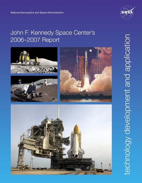
ForewordSuccessful technology development and application projects are critical tomaintaining and enhancing KSC capabilities. Advanced technologies arerequired in order to solve technical problems, resolve operational issues, andoptimize designs of flight and ground systems. When new technologies areinfused in KSC systems and processes, the outcomes are safer, more efficient,and more responsive spaceport and range operations for our customers.The KSC technology development team includes a widevariety of partnerships among civil servants, contractors,academic institutions, and commercial industries. KSCfocuses its advanced technology activities on a list of KSChigh-priority technology needs defined by our primarystakeholders, including current operational programs,future programs, and institutional technical programs.We focus and align our technology investments, personnelinvestments, new project proposals, and strategic partnershipswith the technology needs most important to the programssupporting our Nation’s exploration mission.This report highlights the results of KSC’s applied technologyefforts during <strong>2006</strong>–<strong>2007</strong>. If you have questions or commentsabout applied technology at KSC, please contact me at321-867-7069 or .David E. BartineDirector, Applied <strong>Technology</strong>John F. <strong>Kennedy</strong> <strong>Space</strong> <strong>Center</strong>KSC <strong>Technology</strong> Development and Application <strong>2006</strong>-<strong>2007</strong>i/ii
ii KSC <strong>Technology</strong> Development and Application <strong>2006</strong>-<strong>2007</strong>
Contents<strong>Space</strong>port Structures and Materials.................................................................................... 1Reversible Chemochromic Hydrogen Detectors........................................................................................................................ 2Determining Trajectory of Triboelectrically Charged Particles, Using Discrete Element Modeling............................................. 4Using Indium Tin Oxide To Mitigate Dust on Viewing Ports * <strong>2007</strong> ............................................................................................ 6High-Performance Polyimide Powder Coatings......................................................................................................................... 8Controlled-Release Microcapsules for Smart Coatings for Corrosion Applications * <strong>2006</strong> ........................................................... 10Aerocoat 7 Replacement Coatings........................................................................................................................................... 12Photocatalytic Coatings for Exploration and <strong>Space</strong>port Design * <strong>2006</strong> ........................................................................................ 14New Materials for the Repair of Polyimide Electrical Wire Insulation...................................................................................... 16Commodity-Free Calibration * <strong>2006</strong> ........................................................................................................................................... 18Novel Ice Mitigation Methods * <strong>2006</strong> .......................................................................................................................................... 20Crack Offset Measurement With the Projected Laser Target Device........................................................................................ 22New Materials for Structural Composites and Protective Coatings * <strong>2007</strong> ................................................................................... 24Fire Chemistry Testing of Spray-On Foam Insulation (SOFI).................................................................................................. 26Using Aerogel-Based Insulation Material To Prevent Foam Loss on the Liquid-Hydrogen Intertank........................................ 28Particle Ejection and Levitation <strong>Technology</strong> (PELT)................................................................................................................ 30Electrostatic Characterization of Lunar Dust * <strong>2006</strong> .................................................................................................................... 32Numerical Analysis of Rocket Exhaust Cratering * <strong>2007</strong> .............................................................................................................. 34RESOLVE Projects: Lunar Water Resource Demonstration and Regolith Volatile Characterization......................................... 36Tribocharging Lunar Soil for Electrostatic Beneficiation * <strong>2006</strong> ................................................................................................... 38Numerically Modeling the Erosion of Lunar Soil by Rocket Exhaust Plumes * <strong>2006</strong> ................................................................... 40Trajectory Model of Lunar Dust Particles................................................................................................................................ 42Using Lunar Module Shadows To Scale the Effects of Rocket Exhaust Plumes......................................................................... 44Predicting the Acoustic Environment Induced by the Launch of the Ares I Vehicle................................................................. 46Measuring Ultrasonic Acoustic Velocity in a Thin Sheet of Graphite Epoxy Composite........................................................... 48* <strong>2006</strong>, <strong>2007</strong> <strong>Center</strong> Director’s Discretionary Fund ProjectKSC <strong>Technology</strong> Development and Application <strong>2006</strong>-<strong>2007</strong>iii
Contents (continued)Range Technologies............................................................................................................ 51Hail Size Distribution Mapping............................................................................................................................................... 52Launch Pad 39 Hail Monitor Array System............................................................................................................................. 54Autonomous Flight Safety System – Phase III.......................................................................................................................... 56The Photogrammetry Cube...................................................................................................................................................... 58Bird Vision System.................................................................................................................................................................. 60Automating Range Surveillance Through Radio Interferometry and Field Strength Mapping Techniques................................ 62Next-Generation Telemetry Workstation................................................................................................................................. 64GPS Metric Tracking Unit....................................................................................................................................................... 66<strong>Space</strong>-Based Range................................................................................................................................................................... 68Fluid System Technologies................................................................................................. 71Calibrating the Helium Pressurization System for the <strong>Space</strong> Shuttle Liquid-Hydrogen Tank.................................................... 72Composite Materials for Low-Temperature Applications * <strong>2006</strong> .................................................................................................. 74Mitigating Problems in Measuring Hypergolic Fuels................................................................................................................ 76Cryogenic Moisture Analysis of Spray-On Foam Insulation (SOFI)......................................................................................... 78Thermal Performance of Aged and Weathered Spray-On Foam Insulation (SOFI)Materials Under Cryogenic Vacuum Conditions (Cryostat-4).................................................................................................. 80Automated Method for Estimating Nutation Time Constant Model Parameters for <strong>Space</strong>craft Spinning on Axis.................... 82Parameter Estimation of Lateral <strong>Space</strong>craft Fuel Slosh.............................................................................................................. 84Modeling of Slosh Dynamics in Cryogenic Propellant Tanks in Microgravity Environments................................................... 86Biological Sciences............................................................................................................. 89Countermeasure for Radiation Protection and Repair.............................................................................................................. 90Focused Metabolite Profiling for Dissecting Cellular and Molecular Processesof Living Organisms in <strong>Space</strong> Environments * <strong>2006</strong> .................................................................................................................... 92* <strong>2006</strong>, <strong>2007</strong> <strong>Center</strong> Director’s Discretionary Fund Projectiv KSC <strong>Technology</strong> Development and Application <strong>2006</strong>-<strong>2007</strong>
Contents (continued)Process and Human Factors Engineering Technologies................................................. 95Distributed Observer Network................................................................................................................................................. 96Influence Map Methodology for Evaluating Systemic Safety Issues.......................................................................................... 98Simulation and Analysis of Launch Teams (SALT)................................................................................................................. 100Solid-State Lighting Module (SSLM)..................................................................................................................................... 102Systems Maintenance Automated Repair Tasks (SMART)..................................................................................................... 104Launch and Landing Effects Ground Operations (LLEGO) Model....................................................................................... 106Exploration Supply Chain Simulation.................................................................................................................................... 107Command, Control, and Monitoring Technologies......................................................... 109Nanosensors for Evaluating Hazardous Environments........................................................................................................... 110Sixty-four–Channel Inline Cable Tester................................................................................................................................. 112Wireless Inclinometer Calibration System.............................................................................................................................. 114Generating Safety-Critical PLC Code From a High-Level Application Software Specification................................................ 116<strong>Space</strong>craft Electrostatic Radiation Shielding........................................................................................................................... 118Ion Beam Propulsion Study................................................................................................................................................... 120RT-MATRIX: Measuring Total Organic Carbon by Photocatalytic Oxidation of Volatile Organic Compounds.................... 122Appendix A: KSC High-Priority <strong>Technology</strong> Needs........................................................ 125Appendix B: Innovative Partnership Program................................................................ 129Appendix C: Export Control and Interagency Liaison Division..................................... 135KSC <strong>Technology</strong> Development and Application <strong>2006</strong>-<strong>2007</strong>v/vi
vi KSC <strong>Technology</strong> Development and Application <strong>2006</strong>-<strong>2007</strong>
IntroductionJohn F. <strong>Kennedy</strong> <strong>Space</strong> <strong>Center</strong> (KSC) technology development efforts support NASA’sgoals of increased safety, reduced cost of space access, and expansion of commercialmarkets by applying new technologies in current and future <strong>Space</strong> TransportationSystems.KSC’s role as the nation’s premier launch site creates requirements for new spaceportand range technologies. KSC’s people use our unique institutional resources to providetechnologies to NASA program customers, including designers and operators of spaceportson Earth, lunar bases, and Mars bases. KSC has extensive expertise in designing,building, and operating a spaceport, with all its complex technologies and systems.KSC technology development efforts are categorized by six <strong>Space</strong>port <strong>Technology</strong> andScience Product Lines: <strong>Space</strong>port Structures and Materials; Range Technologies; FluidSystem Technologies; Biological Sciences; Process and Human Factors EngineeringTechnologies; and Command, Control, and Monitoring Technologies. This report isorganized accordingly.The primary stakeholders for spaceport and range technologies are current operationalprograms, future programs, and institutional technical programs. These stakeholdersare illustrated on pages viii and ix. KSC focuses and aligns its technology investments,personnel investments, new project proposals, and strategic partnerships with the technologyneeds most important to our stakeholders in order to maximize benefits for theAgency and the Nation. The specific need addressed by the technology is identifies nextto the High-Priority <strong>Technology</strong> (HPT) icon in each report of results and progress.Through its Innovative Partnership Program, KSC seeks industry participation andcollaboration in its technology development initiatives. Additional information on theInnovative Partnership Program is included in Appendix B. KSC reaches out to transferexpertise and technologies to the commercial sector and academic community. Programsand commercialization opportunities available to American industries and otherorganizations are described in the KSC <strong>Technology</strong> <strong>Transfer</strong> <strong>Office</strong> Internet Web site at. University faculty and postdoctoral fellowshipopportunities are described in the KSC University Programs Internet Web site at.The U.S. Government controls exports of sensitive equipment, software, and technologyas a means of promoting our national-security interests and foreign-policy objectives.This document has been reviewed for export control and intellectual property. Additionalinformation on KSC’s export control function appears in Appendix C.An electronic version of this report is available at .KSC <strong>Technology</strong> Development and Application <strong>2006</strong>-<strong>2007</strong>vii
Primary Stakeholders for KSC <strong>Technology</strong>Development and Application EffortsLaunch VehicleProcessingLaunchServicesProgramInternational <strong>Space</strong> Station/Payload Processingviii KSC <strong>Technology</strong> Development and Application <strong>2006</strong>-<strong>2007</strong>
Constellation SystemsSurfaceSystemsInstitutional Technical Programs• Safety and Mission Assurance• <strong>Center</strong> Operations• Information <strong>Technology</strong> and Communication ServicesKSC <strong>Technology</strong> Development and Application <strong>2006</strong>-<strong>2007</strong>ix/x
KSC <strong>Technology</strong> Development and Application <strong>2006</strong>-<strong>2007</strong>
<strong>Space</strong>port Structures and MaterialsKSC <strong>Technology</strong> Development and Application <strong>2006</strong>-<strong>2007</strong>
Reversible Chemochromic Hydrogen DetectorsThe Florida Solar Energy <strong>Center</strong> (FSEC), affiliated with the University of CentralHazardous-LeakDetection and Florida, has invented a reversible pigment that changes from light beige to blue whenIsolation exposed to hydrogen and back to light beige when exposed to atmospheric oxygen.In laboratory and environmental studies, the FSEC pigment in its tape form failed tochange color adequately when exposed to hydrogen after one day of exposure at <strong>Kennedy</strong> <strong>Space</strong><strong>Center</strong>’s Beach Corrosion Test Facility. The reversible hydrogen-detecting tape also lost its ability tochange color after being placed in an environmental chamber at 45 °C for one day. The first attemptsat extruding the reversible pigment into various polymers were unsuccessful because of the pigment’spoor thermal stability. The goal of this project was to formulate a pigment with improved thermaland environmental stability for extrusion into a variety of appropriate polymer matrices.The formulation of the reversible hydrogen-detecting pigment was modified by removing onereagent and chemically modifying the hydrogen sensitive ingredient. This was intended to improvethe hydrophobicity of the pigment and alter the thermal degradation mechanism. A sensor with thenew pigment was placed in an oven at 45 °C for 3 days. The figure shows how the newly formulatedpigment changed color (∆E) as it was exposed to 100 percent hydrogen. A larger ∆E indicates agreater color difference. The maximum ∆E for the modified sensor decreases by less than 2 followingheat treatment when compared to an unheated sample. With a similar heat treatment, the originalreversible pigment lost its sensitivity to hydrogen, since the maximum ∆E attained is less than 3.After changing color when heated to 45°C, the modified pigment was extruded at high temperaturesinto a tape. The extruded tape retained its color-changing ability.Preliminary results show that the hydrophobicity of the FSEC pigment increases after the pigmenthas been modified; however, further testing is required to validate long-term results in a relevantenvironment.Contacts: Dr. Janine E. Captain , NASA-KSC, (321) 867-6970; andDr. Luke B. Roberson , NASA-KSC, (321) 867-1543Participating Organizations: NASA-KSC (Dr. Robert C. Youngquist), Florida Solar Energy <strong>Center</strong>(Dr. Gary Bokerman, Jessica Macpherson, Dr. Nahid Mohajeri, Dr. Nazim Muradov, and Dr. Ali T-Raissi), ASRCAerospace (Barbara V. Peterson), and University of Central Florida (Cristina M. Berger and Dr. Mary C. Whitten)<strong>Space</strong>port Structures and Materials
20181614∆ E1210Modified Sensor Before Heat TreatmentModified Sensor After Heat TreatmentUnmodified Sensor After Heat Treatment864200 100 200 300 400 500Time (s)Comparison of the detection performance sensors in 100 percent hydrogen.KSC <strong>Technology</strong> Development and Application <strong>2006</strong>-<strong>2007</strong>
Determining Trajectory of Triboelectrically Charged Particles, UsingDiscrete Element ModelingThe <strong>Kennedy</strong> <strong>Space</strong> <strong>Center</strong> (KSC) Electrostatics and Surface Physics Laboratory isContamination participating in an Innovative Partnership Program (IPP) project with an industryControlpartner to modify a commercial off-the-shelf simulation software product to treat theelectrodynamics of particulate systems. The industry partner, DEM Solutions, Inc.,has developed EDEM, a program that can calculate the dynamics of particles. Discreteelement modeling (DEM) is a numerical technique that can track the dynamics of particlesystems. This technique, which was introduced in 1979 for analysis of rock mechanics, wasrecently refined to include the contact force interaction of particles with arbitrary surfaces andmoving machinery. In our work, we endeavor to incorporate electrostatic forces into the DEMcalculations to enhance the fidelity of the software and its applicability to (1) particle processes,such as electrophotography, that are greatly affected by electrostatic forces, (2) grain and dusttransport, and (3) the study of lunar and Martian regoliths [1].After contact force is calculated, additional body forces acting on each particle are calculated. Inthis step, any desired force can be added to the simulation. After the forces on each particle arecalculated, the linear and angular accelerations of each particle are updated according to Newton’ssecond law. Then the positions and orientations of each particle are updated with an explicit timemarchingalgorithm.The introduction of electrostatic forces into the current EDEM configuration requires theaddition of a long-range model that works in conjunction with the existing dynamic calculations.This long-range force model is based on a version of Coulomb’s law [2] that takes into account theelectrostatic screening of adjacent particles. The electrostatic force, F, is given byF = – dU edrq 1q= 2 κ + 14pε 0r r 2(1)where q 1and q 2are the charges of two particles, r is the distance between their centers, ε 0is thepermittivity of free space (8.854 × 10 –12 F/m), U eis the electrostatic potential, and κ is the inverseof the Debye length, λ D, and is based on the local charge concentration.For charge generation, we modify a charge generation equation [3] to model many particles.Q(t) = Nq s(1 – e -at )(2)where N is the number of particles, Q(t) is the total charge on the particles, q sis the saturationcharge, and α is the charge generation constant.We developed a simple inclined-plane apparatus to compare theoretical results with experimentaldata (Figure 1). The inclined plane allowed 500 2.0-mm-diameter glass spheres to roll down overvarious polymer and metal surfaces and into a Faraday cup, where total charge on the spheres wasmeasured. By timing the roll of the spheres down the plane and knowing the total charge, Q(t),we were able to calculate the charge generation constant for the materials under test. The inclinedplanematerials tested were low-density polyethylene (LDPE), polyvinyl chloride (PVC), nylon6/6, polytetrafluoroethylene (PTFE), aluminum, and copper.<strong>Space</strong>port Structures and Materials
Initial results of the EDEM model of the inclined planeshow good comparison to values of Q(t) and α calculatedfrom experimental data. Figure 2 compares the EDEMsimulation output and example Q(t) data.The EDEM modeling tool can be applied to systemsof charged particles that are of interest to NASA, forexample, charged lunar and Martian regoliths. Proposedfuture work includes the addition of dilectrophoreticforce and Van der Waals forces, electrodynamic forcesfrom charged surfaces, and the modeling of nonsphericalparticles.References:[1] C.I. Calle, J.G. Mantovani, E.E. Groop,C.R. Buhler, A.W. Nowicki, M.G. Buehler, andM.D. Hogue, “Electrostatic charging of polymers byparticle impact at Martian atmospheric pressures,”Proceedings ESA-IEJ Joint Meeting, NW University,Laplacian Press, Morgan Hill, California, 2002,pp. 106–117.[2] F.J. Bueche, Introduction to Physics for Scientists andEngineers, 3 rd ed., McGraw-Hill, Inc., 1980, p. 343.[3] W.D. Greason, “Investigation of a test methodologyfor triboelectrification,” Journal of Electrostatics,Vol. 49, Issue 3–4, August 2000, pp. 245–256.Figure 1. EDEM simulation of spheres rolling down theinclined plane.Contacts: Dr. Michael D. Hogue , NASA-KSC, (321) 867-7549; andDr. Carlos I. Calle , NASA-KSC, (321) 867-3274Participating Organization: DEM Solutions, Inc. (Dr. Peter Weitzman and Dr. David R. Curry)Figure 2. Charge-to-mass ratio for 15-degree experiment compared with simulationresults for the six plane materials.KSC <strong>Technology</strong> Development and Application <strong>2006</strong>-<strong>2007</strong>
Using Indium Tin Oxide To Mitigate Dust on Viewing Ports<strong>2007</strong> <strong>Center</strong> Director’s Discretionary Fund ProjectNASA plans to use a number of onboard viewing ports to measure lunar regolith in situContamination and to monitor robotic and human activities on the lunar or Martian surface. BecauseControlof the size and abundance of dust particles on these bodies, the potential for dust toocclude viewing ports and windows is high enough to threaten system lifetime andreliability, especially when activities rely on relaying video to either a habitat module or controllers onEarth.This project uses a technology being developed by KSC’s Electrostatics and Surface Physics Laboratoryto remove dust from windowlike surfaces. The technology applies an alternating electric potential tointerlaced electrodes. In this application, we use indium tin oxide (ITO) to create various electrodepatterns in order to determine the most reliable pattern for dust removal. This technology hasapplication to systems where optical clarity is important. Specifically, this project considers the in situresource utilization (ISRU) application of a viewing port for Raman spectroscopy, where the electrodepattern on glass would be coated with a scratch-resistant sapphire film (Al 2O 3).Electrode patterns were tested in ambient and dry air. These patterns included a single-phase square,single-phase circle, single-phase comb, three-phase square, three-phase circle, and three-phase comb.The voltage, frequency, and waveform applied to each screen were varied in search of the best way toremove dust.Of the patterns tested, the three-phase circular spiral was the most efficient at removing dust. Thecircular pattern minimizes the number of abrupt endings to the electrodes, thereby minimizing thepoints where high electric fields could lead to breakdown and sparking. The screen was tested withJSC-1 lunar simulant particles of less than 25 µm in diameter. A majority of the dust was removedwithin 10 s under ambient conditions and within 5 min under dry-air conditions (near 0 percentrelative humidity).We continued screen testing under vacuum conditions to demonstrate proof of concept in a morerelevant environment. Test parameters were varied in a manner similar to the tests performed underambient and dry-air conditions on a glass screen with a spiral ITO pattern coated with a thin film ofsapphire. The clearing of the dust was similar to the clearing demonstrated under dry-air conditions.An additional test successfully demonstrated the use of the screen on and near metal surfaces. Theproximity of the metal surface did not appear to affect how well the screen removed dust. Applicationsfor using the technology on metals range from dust transport mechanisms to clearing dust from sealsand mechanical joints.Key accomplishments were• developing a technique to apply electrode patterns to ITO-coated glass slides up to 0.7 mm thick,• developing a processing technique to remove the uncoated ITO from the glass slides and coat theslides with an insulating material to prevent sparking, and• optimizing test parameters (voltage, waveform, frequency).Key milestones were• determining an efficient pattern for dust removal,• demonstrating the capability of ITO screens to remove dust under high-vacuum conditions, and• demonstrating the capability of ITO screens to remove dust when backed with grounded andungrounded metal plates.<strong>Space</strong>port Structures and Materials
Contacts: Dr. Carlos I. Calle ,NASA-KSC, (321) 867-3274; and Dr. Jacqueline W. Quinn, NASA-KSC,(321) 867-8410Participating Organizations: ASRC Aerospace(Dr. Charles R. Buhler, Judith L. McFall, andMindy L. Ritz) and Appalachian State University(Dr. Sid Clements)Screen pattern design.A 2.3-cm circular spiral on ITO-coated glass at T = 0 s under dry/ambientconditions.A 2.3-cm circular spiral on ITO-coated glass at T = 8 s under dry/ambientconditions.KSC <strong>Technology</strong> Development and Application <strong>2006</strong>-<strong>2007</strong>
High-Performance Polyimide Powder CoatingsMuch of the infrastructure at <strong>Kennedy</strong> <strong>Space</strong> <strong>Center</strong> and other NASA sites has been subjectedCorrosion to outside weathering effects for more than 40 years. Because much of this infrastructure hasControlmetallic surfaces, considerable effort is continually devoted to developing methods to minimizethe effects of corrosion on these surfaces. These efforts are especially intense at KSC, whereoffshore salt spray and exhaust from Solid Rocket Boosters accelerate corrosion. Coatings of varioustypes have traditionally been the choice for minimizing corrosion, and improved corrosion controlmethods are constantly being researched.Recent work at KSC on developing an improved method for repairing Kapton (polyimide)-basedelectrical wire insulation has identified polyimides with much lower melting points than traditionalpolyimides used for insulation. These lower melting points and the many other outstanding physicalproperties of polyimides (thermal stability, chemical resistance, and electrical properties) led us toinvestigate whether they could be used in powder coatings. In Phase 1 of our research, we found thatpolyimides have the potential to perform effectively as coatings. Physical-property testing of panelscoated with an experimental polyimide formulation indicated that the resulting surfaces were hardand durable, with excellent impact resistance, adhesion, and flexibility. Salt fog corrosion testingrevealed that this formulation performed very well on aluminum substrates but exhibited corrosionand lost adhesion on steel panels. All panels coated with this formulation developed, upon baking,a number of small craters or pin holes, randomly distributed across the coated surface, which weconcluded reduced the formulation’s corrosion performance on steel.In Phase 2, we worked toward developing an effective polyimide powder coating resin. Researchbegan with the goal of significantly improving the soak test adhesion and wetting of a polyimidebasedpowder coating. To soak-test the coating in the laboratory, we immersed the coated couponin a 3-percent sodium chloride solution and observed the progress of delamination and corrosionover time. We identified significant improvements in polyimide powder coating resin performancethrough this screen test. The table shows one powder control and six polyimide formulations tested.Items 5 through 7 showed improved adhesion over the controls, and Item 2 was the best formulationidentified through Phase 1 research.A 1,000-hr salt fog test of Items 5 through 7 revealed significant corrosion resistance over the Phase 1polyimide formula. Figures 1 and 2 highlight this improvement.Results of adhesion and wetting tests.Item Formulation Adhesion Wetting Comments1 DuPont Clear Epoxy 3.5 5.02 Phase 1 Polyimide Formula 2.0 4.5 Phase 1 Salt FogDelamination begins > 14 days3 Phase 2 Polyimide Resin A 5.0 3.04 Phase 2 Polyimide Crosslinker 1.0 4.05 3/4/Epoxy resin/PL 545(8:1:0.7:0.3)w6 3/4/PL 545 (9:0.7:0.3)w3/polyester resin/PL 5455.0 4.5 “Formula 1”5.0 4.5 “Formula 2,” all polyimide7 (9.2:0.5:0.3)w 4.5 4.5 “Formula 3”; no methylacrylic acid (MAA)0: Very poor; 5: Excellent PL 545: flow/leveling aid<strong>Space</strong>port Structures and Materials
Close examination of the corrosionspots on steel panels, shown inFigure 2, revealed that thesecorrosion spots began where smallcraters existed after coating. Nocorrosion was found where thesecraters were not present. Nocorrosion was noted on aluminum,even with the presence of smallcraters.In conclusion, this researchdeveloped polyimide resins with goodmelt properties suitable for coatings.The results of a 1,000-hr salt fog testfor 1-mil polyimide on steel coatingswere encouraging, and excellentsalt fog results were achieved onaluminum panels. This noveltechnology led to the submission oftwo NASA New <strong>Technology</strong> Reports.Figure 1. Steel, Item 4, Phase 1: 525-hour salt fog test.Contacts: Dr. Luz Marina Calle, NASA-KSC,(321) 867-3278; and Dr. David Trejo, Texas A&MUniversity, (979) 845-2416Participating Organizations: ASRCAerospace (Dr. Scott T. Jolley and LillianaFitzpatrick) and University of CentralFlorida (Dr. Mary C. Whitten)Figure 2. Steel, Item 7, Phase 2: 1,000-hour salt fog test.Figure 3. Aluminum, Item 4, Phase 2: 1,000-hour salt fog test.KSC <strong>Technology</strong> Development and Application <strong>2006</strong>-<strong>2007</strong>
Controlled-Release Microcapsules for Smart Coatings for CorrosionApplications<strong>2006</strong> <strong>Center</strong> Director’s Discretionary Fund ProjectCorrosion is a serious problem that has enormous costs and serious safety implications.Corrosion Localized corrosion, such as pitting, is very dangerous and can cause catastrophic failures.Control The NASA Corrosion <strong>Technology</strong> Laboratory at <strong>Kennedy</strong> <strong>Space</strong> <strong>Center</strong> is developing asmart coating based on pH-sensitive microcapsules for corrosion applications. These versatilemicrocapsules are designed to be incorporated into a smart coating and deliver their core contentwhen corrosion starts. Corrosion indication was the first function incorporated into the microcapsules.Current efforts are focused on incorporating the corrosion inhibition function through the encapsulationof corrosion inhibitors into water core and oil core microcapsules. Scanning electron microscopy (SEM)images of encapsulated corrosion inhibitors are shown in Figure 1.Different formulations and conditions have been used to achieve the desired microcapsule size and sizedistribution. Though a homogenous size distribution is normally preferred, different sizes might berequired for different applications. For example, a size of about 20 to 40 µm is suitable for corrosionindication, whereas a smaller size might be better for inhibitor delivery. Figure 2 shows microcapsules ofvarious sizes ranging from 2 to 100 µm.A common concern about incorporating microcapsules into paint systems is that their interaction withpaint constituents could lower the adhesive and protective properties of the paint. The effect of themicrocapsules on several paint properties of interest was tested by incorporating microcapsules intofour representative paint systems (acrylic, epoxy, polyurethane, and siloxane) and applying the paint tosandblasted carbon steel test panels (6×4 in 2 ). The test results showed that, in most cases, incorporatingthese microcapsules into the representative paint systems had no significant effect (more than 15 percent)on the paint adhesion properties. These results are shown in Figure 3.abFigure 1. SEM images of driedmicrocapsules: (a) water core withcorrosion inhibitor Ce(NO 3) 3and(b) water core with corrosioninhibitor Na 2MoO 4.Figure 2. Microcapsules of various sizes.10 <strong>Space</strong>port Structures and Materials
Adhesion at Failure (psi)25002000150010005000Acrylic-33Without MicrocapsuleWith MicrocapsuleAcrylic-HPEpoxy-89Epoxy-64Siloxane-10Siloxane-20PU-13PU-ASA second concern is that the microcapsules mightnot survive the coating process, so the stability of themicrocapsules in the coatings was examined by meansof SEM. Figure 4 shows SEM images of well-dispersedmicrocapsules. The microcapsules appear to be intact andperfectly spherical, thus proving satisfactory survivabilitywith no signs of rupturing.A third concern is that the microcapsules might notkeep the same functionality they exhibited in the colloidsystem or dried-powder form in dried paint. This concernwas investigated through tests the pH sensitivity of themicrocapsules in dry paint. Figure 5 shows the vivid colorchanges observed when the microcapsules in the dry paintwere exposed to basic pH conditions.Figure 3. Adhesion test results.Paint SystemsContacts: Dr. Luz Marina Calle ,NASA-KSC, (321) 867-3278; and Dr. Wenyan Li, ASRC Aerospace, (321) 867-3819abFigure 4. SEM images of epoxy coating with microcapsules captured at(a) 3,500× and (b) 7,500× magnification.Figure 5. Color change observed when microcapsules in dried paint wereexposed to basic pH conditions.KSC <strong>Technology</strong> Development and Application <strong>2006</strong>-<strong>2007</strong>11
Aerocoat 7 Replacement Coatings<strong>Kennedy</strong> <strong>Space</strong> <strong>Center</strong> has used Aerocoat 7 (AR-7) to protect stainless-steel flex hoses atCorrosion Launch Complex (LC-39) and hydraulic lines of the Mobile Launcher Platform (MLP)Controlbecause it provides excellent corrosion protection in low-temperature applications. TheSovereign Company produced AR-7 exclusively for NASA but discontinued productionbecause the coating released high levels of volatile organic compounds (VOCs) and had a significantenvironmental impact. The purpose of this project was to select and evaluate potential replacementcoatings for AR-7 that would be more environmentally sound.The physical and mechanical properties of commercially available coatings were investigated throughthe Internet. The ideal coating would be fluid enough to penetrate the outer mesh of a stainless-steelflex hose and coat the inner hose, and flexible enough to withstand the movement of the hose, as wellas the expansion and contraction of its metal caused by changes in temperature. It would also be easyto apply and prepare samples for testing. Ideally, only a single coat would be necessary, applied bybrushing, spraying, or dipping.Forty-one coatings were initially selected. After evaluating the candidates against informationobtained from the Internet and coating manufacturers, we narrowed the list to 15 coatings. After thecoatings were applied, six were removed from consideration because of their reactivity, short pot life,or long curing time.Accelerated corrosion tests were performed in the salt fog chamber of the NASA Corrosion<strong>Technology</strong> Laboratory, according to the guidelines of ASTM B117. After 500 hours of exposure,five coatings performed as well as or better than AR-7 and two others were eliminated from thestudy. Figure 1 shows coatings that performed worse than AR-7, the same as AR-7 (AR-7 was thecontrol), and better than AR-7. Sample (a) was one of the coatings eliminated from the study.After 1,000 hours in the chamber, even the best-performing coatings had blisters or creepage alongthe scribe. Only two of the unscribed coatings had no blisters or corrosion spots. The four bestperformers were selected for long-term exposure testing, and scribed samples of these coatings areshown in Figure 2. After 1,500 hours of exposure, none of the coatings performed as well as thecontrol.This study will continue through FY 2008 with further atmospheric exposure and cryogenic testing.Before being included in the list of qualified products in NASA-STD-5008, the replacement forAR-7 must demonstrate that it provides acceptable corrosion protection after exposure for 18 monthsat the NASA Corrosion <strong>Technology</strong> Laboratory beachside atmospheric-exposure test site.Contact: Dr. Luz Marina Calle , NASA-KSC, (321) 867-3278Participating Organizations: NASA-KSC (Janice K. Lomness) and ASRC Aerospace (Rubiela D. Vinje andJerome P. Curran)12 <strong>Space</strong>port Structures and Materials
Figure 1. After 500 hours of salt fog exposure, coatings performed (a) worsethan AR-7 (the control coating) and (c) better than AR-7.Figure 2. After 1,000 hours of salt fog exposure, all of the coatings showed degradation.KSC <strong>Technology</strong> Development and Application <strong>2006</strong>-<strong>2007</strong>13
Photocatalytic Coatings for Exploration and <strong>Space</strong>port Design<strong>2006</strong> <strong>Center</strong> Director’s Discretionary Fund ProjectCorrosionControlThis project developed self-cleaning photocatalytic coatings that remove contaminationwithout human intervention. The coatings chemically remove organic contaminants and leaveno residue. The photocatalyst will not negatively affect other coating properties, especiallycorrosion resistance.Titanium dioxide, TiO 2, is an extremely popular photocatalyst because of its chemical stability,nontoxicity, and low cost. TiO 2is commonly used in the photocatalytic oxidation of organic matteror pollutants in the gas and liquid phases. However, TiO 2does have some drawbacks. It has limitedlight absorption because of its large band-gap and suffers from a photonic efficiency of less than10 percent for organic degradation. Dopants can lower the band-gap and improve efficiency. Sincethe photocatalytically active form of TiO 2is a nanocrystalline powder, it can be difficult to make arobust coating with enough catalyst loading to be effective.Photocatalysts become active when certain light energy is absorbed. When photons with an energygreater than the band-gap, E g, (wavelengths shorter than 400 nm) impinge upon the surface of theTiO 2, an electron-hole pair is formed (Figure 1). The electron-hole pair oxidizes adsorbed substanceseither directly or via reactive intermediates that form on the surface, such as hydroxyl radicals (OH·)or superoxide ions (O 2–).Several factors can influence the band-gap energy of TiO 2, two of which are crystal structure andimpurities. TiO 2exists as three crystal structures—brookite, anatase, and rutile—that can becontrolled via heat treatment. Anatase is the most photocatalytically active crystal form of TiO 2.Doping TiO 2with impurities can alter its band-gap energy, as well as its effectiveness as a catalyst.Depending on their size, dopant atoms can occupy either the substitutional or interstitial latticepositions. Atoms that are relatively large will assume the interstitial positions and create a muchgreater energy disturbance in the crystal than will smaller atoms that take on the substitutionalpositions. This energy disturbance narrows the band-gap and thus allows photons with longerwavelengths and smaller energies (such as those in the visible-light spectrum) to create electron-holepairs.Raman spectroscopy was performed for the purpose of determining the crystal structure and thedegree of crystallinity of the TiO 2particles. Reflectance measurements indicated the wavelengthsof light absorbed by the different catalysts. Reflectance is inversely proportional to absorbance andcan help approximate the band-gap. The wavelength where the percentage of reflectance beginsto decrease approximates the band-gap. For pure TiO 2, only the sample heated to 600 °C exhibitsdifferent spectral behavior from the others. Its rutile crystal structure ended its absorbance near awavelength of 460 nm instead of the 435-nm wavelength characteristic of the other samples in theanatase phase.For the catalysis evaluation, 20 µL of 0.2-mg/mL Rhodamine B dye in ethanol was added to10-mg samples of the catalyst. Half of the prepared samples were exposed to ultraviolet (UV)radiation (from an F8T5/BLB fluorescent light with peak emission at 365 nm) for 24 hours, whilethe other half were kept in the dark. Upon completion of the UV test, the addition of 5 mL of waterdissolved the remaining dye. The absorbance of the dye, measured with an HP spectrophotometer,between 450 nm and 615 nm, revealed the amount of dye remaining after exposure. The effectivenessof each catalyst was determined by the comparison of the amount of absorbance of the dye remainingin the samples with the initial absorbance of the dye alone. All measurements were made in triplicate.Figure 2 shows results for the cleaning efficiency of pure TiO 2made with three different proceduresand different heat treatments. Procedure 3 with a heat treatment at 400 °C performed the best. Ingeneral for all the doped catalysts, Procedure 3 with the same heat treatment performed the best.14 <strong>Space</strong>port Structures and Materials
Contacts: Dr. Paul E. Hintze , NASA-KSC, (321) 867-3751; andDr. Luz Marina Calle , NASA-KSC, (321) 867-3278Participating Organizations: NASA-KSC (Amanda B. Napier) and ASRC Aerospace (Jerome P. Curran)e –Conduction BandE ghνValence Bandh +Figure 1. Electronic band structure of a semiconductor showingthe electron-hole pair formed after it absorbs a photon of light.100Procedure 1 Procedure 2 Procedure 3908070Dye Removal (%)6050403020100NHT 200 400 600Heat Treatment (°C)Figure 2. Dye reduction after the catalyst was exposed to UV light for 24hours. The catalyst was pure TiO 2made in three ways with different heattreatments. The high percentage reduction indicates that the catalystoxidized nearly all the dye in contact with the surface. NHT indicates noheat treatment.KSC <strong>Technology</strong> Development and Application <strong>2006</strong>-<strong>2007</strong>15
New Materials for the Repair of Polyimide Electrical Wire InsulationTwo viable polyimide backbone materials have been identified that will allow the repair ofWire/CableInspection polyimide electrical wire insulation found on the <strong>Space</strong> Shuttle and other aging aircraft.and Repair This identification is the outcome of ongoing efforts to assess the viability of using suchpolyimides and polyimide precursors (polyamic acids [PAAs]) as repair materials for agingpolyimide electrical wire insulation. These repair materials were selected because they match thechemical makeup of the underlying wire insulation as closely as possible. This similarity allowsfor maximum compatibility, coupled with the outstanding physical properties of polyimides.The two polyimide backbone materials allow the polymer to be extremely flexible and to melt atlow temperatures. A polymer chain end capping group that allows the polymer to crosslink intoa nonflowable repair upon curing at around 200 ºC was also identified. The table highlights tworepair materials prepared from each of the two backbone materials identified. Two films, one fromeach backbone, are soft, flexible films suitable for manually wrapping damaged wire. The other twoare stiffer, more rigid films to be formed into “sleeves” that can easily be slipped onto a wire. Bothof the wire repair materials achieved excellent results. Figure 1 shows that the repairs (on 12-gaugepolyimide insulated wire) are small and compact, exhibiting excellent flexibility. Methods have alsobeen established to repair electrical wire insulation based on fluoropolymers (polytetrafluoroethylenematerials [Figure 2]). In addition, a heater was developed to melt and flow the materials, whichenables the curing process required for repairs. A portable soldering iron was modified with a customhead designed to accommodate a wire wrapped with repair film. Figure 3 shows the wire holders thatwere modified for repairing wires.Characteristics of repair materials prepared from two viable polyimide backbone materials.Polymer Type Film FormingAbilityWire RepairResultsCommentsA-1 Imide Excellent Good Soft for wrapping; very good on voltage breakdownA-2 Imide Excellent Good Stiff for sleeve type repairB-1 Imide Excellent Good Soft for wrapping; v. good adhesionB-2 Imide Excellent Good Stiff for sleevesFigure 1. Small, compact repairs on 12-gauge insulated wires exhibit excellent flexibility.16 <strong>Space</strong>port Structures and Materials
Figure 2. Repairs to various types of wire insulation materials.Figure 3. Wire holders modified for repairing wires.Contacts: Dr. Tracy L. Gibson , (321) 867-7572, and Dr. Scott T. Jolley (321) 867-7568, ASRC Aerospace; and Dr. Martha K. Williams, NASA-KSC, (321) 867-4554Participating Organizations: NASA-KSC (Dr. LaNetra C. Tate, Trent M. Smith, and Dr. Luke B.Roberson) and ASRC Aerospace (Lilliana Fitzpatrick, Rubiela D. Vinje, and Steven L. Parks)KSC <strong>Technology</strong> Development and Application <strong>2006</strong>-<strong>2007</strong>17
Commodity-Free Calibration<strong>2006</strong> <strong>Center</strong> Director’s Discretionary Fund ProjectPropellant Loading/Servicing/StorageCommodity-free calibration is a reaction rate calibration technique that does not requirethe addition of any commodities. This technique is a specific form of the reaction ratetechnique, where all of the necessary reactants, other than the sample being analyzed, areeither inherent in the analyzing system or specifically added or provided to the systemfor a reason other than calibration.After introduction, the component of interest is exposed to other reactants or flow paths alreadypresent in the system. The instrument detector records one of the following to determine the rateof reaction: the increase in the response of the reaction product, a decrease in the signal of theanalyte response, or a decrease in the signal from the inherent reactant. With this data, the initialconcentration of the analyte is calculated.This type of system can analyze and calibrate simultaneously, reduce the risk of false positivesand exposure to toxic vapors, and improve accuracy. Moreover, having an excess of the reactantalready present in the system eliminates the need to add commodities, which further reduces cost,logistic problems, and potential contamination. Also, the calculations involved can be simplified bycomparison to those of the reaction rate technique.We conducted tests with hypergols as an initial investigation into the feasablility of the technique.Hypergols are prime candidates for commodity-free calibration because they are highly toxic andexceptionally reactive. Consequently, these vapors present considerable challenges in handlingand quantification. After characterization, nitrogen tetroxide (NTO) vapors were collected at lowconcentrations (about 10 ppm) in a fixed-volume gas collection tube. At t = 0, immediately aftervapor collection, an acidic N-(1-naphthyl)ethylenediamine dihydorochloride (“diamine”) solutionwas injected through a septum into the collection tube containing the trapped vapors. The NTOvapors were allowed to react with the absorbing solution for a reaction time, t. At the given t, thecontents of the collection tube were emptied into a cuvette and absorbance was measured with aUV-Vis spectrophotometer. We conducted separate experiments with t ranging from 1 to 15 minand plotted the resulting data to generate a reaction profile of instrument response versus time forthis reaction (Figure 1). The resultant curve merely approximates the actual reaction profile becauseits data reflects a series of reactions rather than a singlereaction monitored over time. However, these results dolook promising in that the reaction proceeds at a ratereasonable for use in analysis.Figure 1. Reaction rate profile.To monitor the kinetics of a single reaction, we designeda custom UV-Vis cuvette (Figure 2) that could be placedin the spectrophotometer, with a gas sample beingintroduced at t = 0. Time-based absorbance measurementswould monitor the formation of the product, and fromthe resulting data, the concentration of the NTO vaporscould be calculated. Reaction reversibility is crucialin order for this procedure to fit the commodity-freerequirement. If the reaction were not reversible, thecommodity expended during operation would need tobe replenished. For demonstration, NTO vapors werereacted with a diamine solution. Time-based absorbancemeasurements were taken during the process, and theresults are plotted in Figure 3. The spherical bubble18 <strong>Space</strong>port Structures and Materials
on top of the cuvette contains the NTO vapors andmaximizes the solution-vapor interaction under theserestricted reaction conditions. Upon delivery of thecuvette, reaction profiles from singular reactions over timecan be generated. The plot of the log of the absorbanceintensity (which is proportional to the productconcentration) versus reaction time should be linear, witha slope that represents the reaction rate constant, k.We studied the feasibility of using reaction time tocalibrate a wide range of sensors and tested colorindicatingchemistry as a way to track the reactionprogress. We also developed systems using computercontrol, rather than color, to ensure the results areconsistent. Our tests of these systems are showingpromise for refining the technique. Future work includesfinishing studies using the thermal desorption system todemonstrate if the technology is feasible for NASA’s goals.Other reaction techniques could also be examined todetermine the best approach.Contacts: Dr. Timothy P. Griffin , NASA-KSC, (321) 867-6755; and Dr. C Richard Arkin, ASRC Aerospace,(321) 867-6757Participating Organization: ASRC Aerospace (Cristina M. Berger)Figure 2. Custom-built UV-Vis cuvette.Figure 3. Time-based absorbance of NTO.KSC <strong>Technology</strong> Development and Application <strong>2006</strong>-<strong>2007</strong>19
Novel Ice Mitigation Methods<strong>2006</strong> <strong>Center</strong> Director’s Discretionary Fund ProjectAfter the loss of Columbia, there was great concern in the <strong>Space</strong> Shuttle program forPropellant Loading/ the impact of debris against the leading edges of the Orbiter wings. It was quicklyServicing/Storagerecognized that, in addition to impacts by foam, ice that formed on the liquid-oxygenbellows running down the outside of the External Tank could break free during launchand hit this sensitive area. A number of possible solutions were considered, and eventually heaterswere installed in this area. This allowed Shuttle launches to resume, but adding heat to the cryogenicflow system was not an optimal solution. Consequently, the Shuttle program requested that a <strong>Center</strong>Director’s Discretionary Fund (CDDF) project explore possible alternatives.Previously both the Shuttle program and the NASA Engineering and Safety <strong>Center</strong> had fundedextensive efforts for ice mitigation. Many concepts were examined in detail, such as encapsulatingthe area, projecting heat, using flexible insulation, and applying innovative coatings, but all haddrawbacks that prevented them from being used. So it was decided that the CDDF project wouldnot devote resources to concepts that had already been heavily explored, and instead wouldconcentrate on novel ideas that were potentially applicable. Patent and literature searches, as well asbrainstorming sessions, resulted in a number of interesting concepts to be considered.The resulting list of ideas was further filtered to remove ones that, while not considered forDiscovery’s return to flight, were already well developed and understood (for example, electroexpulsiveice removal). In the end, four concepts were chosen for testing and possible development:(1) adding compounds to the ice to affect its hardness, (2) using dark coatings to increase infraredabsorption, (3) using shape memory alloys to break ice free, and (4) applying a high electric fieldwith low-adherence coatings to repel ice.Figure 1. Ice sheet construction involved clamping a sheet of aluminum to aflat, liquid-nitrogen dewar and then spraying the surface with a water mist. Thealuminum sheet had both white and dark surfaces, the idea being that the darksurfaces would absorb more radiation and melt the ice more quickly. In thepicture, radiative heat has been applied to the panel for some time, warmingthe center region of the panel and melting the ice.20 <strong>Space</strong>port Structures and Materials
Figure 2. A corrugated NiTi sheet exhibiting a shape metal alloy effect was used in this experiment. As the timelineevolution from the upper left to the lower right shows, heating causes the corrugated pattern to return back to itsbowed shape, ejecting the ice. The thick ice chunks shown in the last frame demonstrate the enormous stressforce that the NiTi can exert.Adding compounds to affect the hardness of ice could proceed in two directions; one idea was to formweak ice, which factures easily and into small pieces, whereas a second idea recommended forming strongice, thus minimizing ice shedding during launch. Various additives were shown to affect ice hardness, butsignificant amounts of these additives were required to achieve the desired goals, precluding this as a viableapproach.Infrared radiation tests were performed on 2-ft-square aluminum sheets on which ice had been grown(Figure 1). These sheets were painted with white and black regions so that the dark areas would absorb moreheat from the radiation and melt the ice more quickly. In testing, though, this did not happen, probablybecause the ice itself reflected and absorbed much of the radiation before it reached the underlying coating.The most successful of the new concepts for ice mitigation involved shape memory alloy materials. Thesematerials can be bent into a given shape and, when heated, will return to their original shape. Figure 2shows a piece of nickel titanium (NiTi) bent into a corrugated pattern and then chilled until a thick layer ofice formed on it. Then, after being heated, it returns to its original shape, throwing off the ice. This approachproved repeatable and, if further development were requested, would be our primary recommendation.Our final concept explored how to use very high-voltage electric fields to eject ice as it is being formed. Veryhigh-voltage fields were observed to cause ice to form in fine fingerlike structures and fly off. Special coatingsminimized the attachment of the ice to a surface, and then high voltages were applied to see if they couldrepel the ice from the surface. This approach did not work consistently and, after several tries, was dropped.Contacts: Trent M. Smith
Crack Offset Measurement With the Projected Laser Target DeviceThe device and associated analysis methodology summarized in this report were developedDefect/Damage for the purpose of estimating the size of discontinuities in the surface of the foam thatLocationcovers the <strong>Space</strong> Shuttle External Tank. These surface offsets are thought to be due tosubsurface cracks in the foam insulation. The mathematical analysis and proceduredescribed here provide a method to quantity the dimensions of the crack offset in a directionperpendicular to the surface, making use of the projected laser target device (PLTD) tool and a laserline projector.The keys to the construction and use of the PLTD are the following geometrical design requirements:• Laser dots are on a square grid: length α on a side.• Laser beams are perpendicular to projected surface.• Beams are parallel out to the distance being projected.Figure 1. The projected laser target device (PLTD).Figure 2. Test setup, with a camera, PLTD, and a laser line projector.22 <strong>Space</strong>port Structures and Materials
The PLTD can be used to (1) calibrate fixed camerasof unknown magnification and orientation (far-fieldsolution); (2) provide equivalent calibration to multiplecameras, previously achieved only by the use of knowntarget points, for example, in 3‐D foreign-object debristracking on a fixed launch platform; (3) compute scalingfor conventional 2‐D images, and depth of field for 3‐Dimages (near-field solution); and (4) in conjunction witha laser line projector, achieve accurate measurements ofsurface discontinuity (cracks) in a direction perpendicularto the surface.Figure 5. Data extracted from image analysis (Figure 4) foroffset measurement.Figure 6. Analysis of data from Figure 5.Figure 3. Setup for measuring vertical offset of test objects.Figure 4. Image analysis of test in Figure 3.Figure 7. Plot of test data, showing measured offsetscompared to actual offsets.Contact: Dr. Robert C. Youngquist , NASA-KSC, (321) 867-1829Participating Organizations: NASA-KSC (Charles G. Stevenson) and ASRC Aerospace (Dr. John E. Lane)KSC <strong>Technology</strong> Development and Application <strong>2006</strong>-<strong>2007</strong>23
New Materials for Structural Composites and Protective Coatings<strong>2007</strong> <strong>Center</strong> Director’s Discretionary Fund ProjectThe objective of this Phase I project was to create novel conductive materials that areDefect/Damage lightweight and strong enough for multiple ground support equipment and ExplorationLocationapplications. The long-term goal is to combine these materials within specially designeddevices to create composites or coatings with diagnostic capabilities, increased strength,and tunable properties such as transparency, electroluminescence, and fire resistance. One suchtechnology application is a “smart windows” system. In such a system, the transmission of lightthrough a window is controlled by electrical power. In the future, these materials may also be able toabsorb sunlight and convert it into electrical energy to produce light, thereby creating a self-sufficientlighting system.This experiment, conducted in collaboration with the Georgia Institute of <strong>Technology</strong>, demonstratedenhancements in fabricating fiber materials from carbon nanotubes (CNT). These nanotubes weregrown as forests in an ultra-high-purity chemical vapor deposition (CVD) furnace and then drawn,using novel processing techniques, into fibers and yarns that would be turned into filaments. Thiswork was submitted to the Journal of Advanced Functional Materials.The CNT fibers were initially tested as filament materials at atmospheric pressure; however, evenunder high current loads, the filaments produced only random sparking. The CNT fibers were alsoconverted into transparent, hydrophobic, and conductive sheets. Filament testing at low vacuumpressures is in progress, and the technology will be enhanced in 2008.As initial proof of the smart-windows application concept, the use of CNT sheets as composites/protective coatings was demonstrated in collaboration with Nanocomp Technologies of Concord,New Hampshire. CNT sheets were thermally welded between layers of high-performance polymersheets with high thermal conductivity. The electrical conductivity of the sheets provided an ampleflow of current to detect damage.Enhancements to the fabrication process and performance of this type of system will be addressedin FY 2008. In Phase II, we intend to further address conductive composites, fabrication processes,and various applications. We will apply these next-generation composites and coatings to varioushardware systems and analyze their mechanical properties, conductivity for detection, and thermalconductivity for thermal management in Lunar Architecture Team and Exploration applications.Key accomplishments included fabricating CNT filaments and evaluating them under atmosphericconditions, fabricating CNT sheet fabrication, and fabricating a structural conductive compositewith ample current for damage detection.Contacts: Dr. Luke B. Roberson , NASA-KSC, (321) 867-1542;Dr. LaNetra C. Tate , NASA-KSC, (321) 867-3789; and Dr. Martha K. Williams, NASA-KSC, (321) 867-4554Participating Organizations: NASA-KSC (Trent M. Smith and Dr. Robert C. Youngquist), Georgia Institute of<strong>Technology</strong> (Dr. Satish Kumar, Dr. Jud Ready, and Dr. Janusz Kowalik), Nanocomp Technologies, Inc.(Dr. David Lashmore), and ASRC Aerospace (Dr. Barry J. Meneghelli and Dr. Christopher D. Immer)24 <strong>Space</strong>port Structures and Materials
SEM images of neat MWNT fibers: (a) as-drawn aerogel fiber, (b) nanotube arrangements in theas-drawn fiber, (c) densified fiber, and (d) nanotube arrangement in the densified fiber.Spinning continuous MWNT fibers from the forest: (a) fiber in the process of being drawnfrom the 10- by 10-mm 2 wafer scale forest and (b) optical image showing the nanotubesbeing pulled from the forest wall into a fiber.KSC <strong>Technology</strong> Development and Application <strong>2006</strong>-<strong>2007</strong>25
Fire Chemistry Testing of Spray-On Foam Insulation (SOFI)An experimental study was initiated that included the long-term testing of the followingFlight Environment SOFI materials, which make up the majority of the Thermal Protection System of theMeasurementShuttle External Tank: NCFI 24-124 (acreage foam) and BX-265 (close-out foam,including the intertank flange and bipod areas). A potential alternate material, NCFI27-68 (acreage foam with flame retardant removed), was also tested. Specimens of all three foammaterials were placed at two locations: an aging site (Vehicle Assembly Building [VAB]) and aweathering site (Atmospheric Exposure Test Site, [beach site]). Fire chemistry testing was completedon samples that were retrieved after aging/weathering at intervals of 3, 6, and 12 months. The testingincluded three standard test methods: limiting oxygen index (ASTM G125), radiant panel(ASTM E162), and cone calorimeter (ASTM E1354).During the 12-month weathering period, all foams showed little to no change in the limiting oxygenindex (LOI). The LOI test, which measures the ease with which a flame is extinguished, indicatedthat NCFI 24-124 is an inherently flame-retardant material, whereas BX-125 and NCFI 27-68 arenot. In essence, all foams tested will burn in an enriched-oxygen atmosphere (i.e., oxygen leak).Figure 1 shows the results of the LOI test.The results of radiant-panel testing, which measures the critical ignition energy for a sample (flamespread factor) along with heat evolution, showed that the flame spread was quite high forNCFI 27-68 and BX-265 and that the flame spread rate increased with aged samples. A rind surfaceburns hotter, but slower (downward) than a machined surface for NCFI 27-68. The rind surfaceis also more susceptible to upward flash fire, according to the flame spread index. Both aging andweathering of SOFI samples increased the flame spread index.Cone calorimetry measures the peak heat release of a sample, along with the heat release rate, time toignition, and smoke density. The heat release rates of BX-265 and NCFI 27-68 were not affected bythe aging or weathering of these materials as measured by cone calorimetry. However, weathering didreduce the heat release rate of NCFI 24-124 as measured by cone calorimetry. The flame spread indexand heat evolution factor were higher for samples with a rind, which reached the peak heat releaserate faster. Samples with a rind also burned faster and hotter. The order of heat release rate based onmachined data was BX-265 > NCFI 27-68 > NCFI 24-124. Additional samples will be tested toconfirm these preliminary results.LOI test results for SOFI foam samples (3-, 6-, and 12-month composites).26 <strong>Space</strong>port Structures and Materials
Contacts: Trent M. Smith
Using Aerogel-Based Insulation Material To Prevent Foam Losson the Liquid-Hydrogen IntertankUninsulated areas on cryogenic propellant tanks and feedlines cause moisture in theFlight Environment air to condense or ice to form. Flange joints, bracket supports, expansion bellows,Measurementand other cavities are uninsulated by design. These areas cannot be sealed becauseconventional thermal insulation materials would restrict mechanical articulations.Aerogel-based thermal insulation systems are able to seal critical locations such as the liquid-oxygen(LO 2) feedline bellows.A new thermal insulation system was also necessary between the intertank wall, flange, and theliquid-hydrogen (LH 2) tank dome, where there is a cavity (or crevice) with an exposed 20-K surface.When nitrogen gas is used for purging within the intertank volume, it condenses on this coldsurface. Some solid nitrogen may also form on the colder side of the crevice. Voids or discontinuitieswithin the foam can pressurize and cause areas of foam to weaken and break off, reducing thermalefficiency and creating potentially dangerous debris.To prevent this foam loss, we developed a thermal insulation system using bulk-fill aerogel materialand demonstrated it with a one-tenth-scale model of the LH 2intertank flange area (Figure 1).Temperature sensors were placed in the crevice, in the intertank barrel section, and on the foamsurfaces (Figure 2). Cold helium gas sprayed onto the underside of the tank dome helped tomaintain a cold-boundary temperature of 20 K ±5 K, and two electric tape-heaters on the lid helpedto maintain a warm-boundary temperature of 300 K ±2 K. The intertank volume was purged withnitrogen gas at a controlled flow rate to maintain a thermal balance within the system, with the hotsidelid at 300 K and the cold-side tank dome at 20 K. The aerogel insulation dramatically reducednitrogen cryopumping and generally increased temperatures throughout the intertank. Only a thinlayer of aerogel insulation was required in order to prevent liquid nitrogen (LN 2) from forming. Theaerogel material remained completely dry and friable (no free LN 2) in all cases.These aerogel bulk-fill materials and other aerogel-based insulation systems are viable new optionsfor the design and safe operation of cryogenic propellant tanks.Contacts: Jared P. Sass , NASA-KSC, (321) 867-0694; and James E. Fesmire, NASA-KSC, (321) 867-7557Participating Organization: ASRC Aerospace (Dr. Barry J. Meneghelli, Philip A. D’Andreamatteo, andGary L. Wall)28 <strong>Space</strong>port Structures and Materials
Figure 1. An isometric cutaway view of the LH 2intertank demonstrationtest unit, showing main features.Figure 2. Section view of one-tenth–scale demonstration test unit, showingtemperature sensor.KSC <strong>Technology</strong> Development and Application <strong>2006</strong>-<strong>2007</strong>29
Particle Ejection and Levitation <strong>Technology</strong> (PELT)Each of the six Apollo landers touched down at unique sites on the lunar surface. AsideLunar Launch/Landing Site from the Apollo 12 landing site located 180 meters from the Surveyor III lander, plumeEjecta Mitigation impingement effects on ground hardware during the landings were not a problem. Theplanned return to the Moon requires numerous landings at the same site. Since the topfew centimeters of lunar soil are loosely packed regolith, plume impingement from the lander willeject the granular material at high velocities. Figure 1 shows what the astronauts viewed from thewindow of the Apollo 14 lander. There was tremendous dust excavation beneath the vehicle. Withhigh-vacuum conditions on the Moon (10 –14 to 10 –12 torr), motion of all particles is completelyballistic. Estimates derived from damage to Surveyor III caused by the Apollo 12 lander showthat the speed of the ejected regolith particles varies from 100 m/s to 2,000 m/s. It is imperativeto understand the physics of plume impingement to safely design landing sites for future Moonmissions.Aerospace scientists and engineers have examined and analyzed images from Apollo video extensivelyin an effort to determine the theoretical effects of rocket exhaust impingement. KSC has joined theUniversity of Central Florida (UCF) to develop an instrument that will measure the 3-D vectorof dust flow caused by plume impingement during descent of landers. The data collected from theinstrument will augment the theoretical studies and analysis of the Apollo videos.Instrumentation designs and concepts were tested in a custom-designed wind tunnel that allows abed of granular material to be eroded. The material erosion can be measured from altitudes similarto those at which the lunar erosion first begins: up to 30 m. The wind tunnel chamber operates atatmospheric pressure; however, ρV 2 (one of the important scaling parameters) is approximatelythe same as those for the lander cases on the Moon. Figure 2 shows yellow quartz sand flowing in asection of the wind tunnel. Figure 3 shows 2-D flow calculations of a scene similar to that shown inFigure 2.The instrument can also measure other lunar surface dust effects, such as dust levitated by solarcharging. Though most of the effort for the current instrument has been focused toward lunarapplications, the instrument is quite general and could easily be adapted to other applications such asMartian landings.Figure 1. Example view taken during descent of Apollo lander. The dustis eroding from the lower left to the upper right.30 <strong>Space</strong>port Structures and Materials
Figure 2. Quartz sand flowing in the wind tunnel used to test the PELT instrumentation designs.Figure 3. Example flow pattern of a scene similar to that shown in Figure 2.Contact: Dr. Philip T. Metzger , NASA-KSC, (321) 867-6052Participating Organizations: ASRC Aerospace (Dr. Christopher D. Immer) and University of Central Florida (Dr. Jannick Rolland)KSC <strong>Technology</strong> Development and Application <strong>2006</strong>-<strong>2007</strong>31
Electrostatic Characterization of Lunar Dust<strong>2006</strong> <strong>Center</strong> Director’s Discretionary Fund ProjectTo ensure the safety and success of future lunar exploration missions, it is important toLunar Launch/Landing Site measure the toxicity of the lunar dust and its electrostatic properties. The electrostaticEjecta Mitigation properties of lunar dust govern its behavior, from how the dust is deposited in anastronaut’s lungs to how it contaminates equipment surfaces. Astronaut Harry Schmidtsaid, “Dust is going to be the environmental problem for future missions, both inside and outside thehabitats.” NASA has identified the threat caused by lunar dust as one of the top two problems thatneed to be solved before returning to the Moon.The main reason lunar dust adheres to surfaces is its electrical charge, and the dry conditions on theMoon increase those adhesive properties. The Apollo 12 Mission Briefing report stated that “thecohesive properties of the lunar dust in vacuum, augmented by electrostatic properties, tend to makeit adhere to anything it contacts.”To understand the electrostatic nature of lunar dust, NASA must answer the following questions:(1) how much charge can accumulate on the dust? (2) how long will the charge remain? and(3) can the dust be removed? These questions can be answered by measuring the electrostaticproperties of the dust: its volume resistivity, charge decay, charge-to-mass ratio or chargeability, anddielectric properties. The volume resistivity of a material indicates the likelihood that the particleswill acquire a charge and their ability to dissipate the charge. Charge decay measurements give thetime it takes for samples to dissipate the applied charge. The charge-to-mass ratio (chargeability)measurements indicate the amount of charge the dust is likely to acquire during specific processes.The dielectric properties of the dust give a measure of the dust’s ability to polarize.All lunar dust samples that were returned to Earth have been contaminated by air. Thiscontamination most likely affected the electrostatic properties of the material through oxidation.The addition of oxygen atoms to the surface changes the surface chemistry, lowers the surface freeenergy, and changes the work function of the material. In many cases, these properties influencethe magnitude and sign of the charges exchanged between materials, which in turn influences theelectrostatic properties. These relationships illustrate the importance of measuring the electrostaticFigure 1. Schematic of the side profile of the design of the test cell usedthroughout the experiments.32 <strong>Space</strong>port Structures and Materials
Figure 2. Top images show how the electrodes are sandwiched between apolycarbonate spacer and two backsides to form the cell. Bottom image is atop view of the test cell.properties of lunar regolith in situ. Research performed in the Electrostatics and Surface Physics Laboratory at KSChas led to the development of a device that can be incorporated onto a lander or a rover for measuring all fourelectrostatic properties during future lunar missions.A test cell was developed for experimentation with this device before using it on a lander or rover. This test cellcompiled with standards in ASTM D 150 as well as British Standard (BS) 5958 in measuring the volume resistivityof powders. Figures 1 and 2 shows the test cell construction: a guard, a guarded electrode, and a shield on oneplate; and a high-voltage electrode and a shield on the other plate. All tests with this test cell were performed invacuum with Minnesota Lunar Simulant (MLS)-1. Because of its mineralogical composition, MLS-1 is believedto be a good lunar soil simulant, even though it does not contain glass or agglutinates. Once the material wasdelivered to the test cell, it was not disturbed. To measure the four different electrostatic properties, we onlyneeded to change the electrical connections in test setup. This was done outside the test cell without disturbing theregolith.The experiment mimicked how soils on the lunar surface may one day be handled. They would most likely becollected with a metal scoop or container and poured onto or into a sensitive device that could be damaged bythe electrostatic fields produced by highly charged dust. Results of the chargeability test showed relatively highcharge-to-mass ratios when the dust was poured onto the test cell. The results were not unexpected in the highvacuumconditions used during the test. Dielectric measurements of the soil showed no fluctuation of the dielectricconstant with frequency, which suggested the absence of moisture, and gave a dielectric constant of about 4.Volume resistivity measurements were made after the soil stabilized for several minutes. The values fell within theappropriate range for highly insulating silicate materials and were consistent with the literature on lunar fines. Thecharge decay measurements, made by induction-charging the soil, were also consistent with the literature and thepreviously measured electrostatic properties.Contact: Dr. Carlos I. Calle , NASA-KSC, (321) 867-3274Participating Organizations: ASRC Aerospace (Dr. Charles R. Buhler and Mindy L. Ritz) and Appalachian State University(Dr. Sid Clements)KSC <strong>Technology</strong> Development and Application <strong>2006</strong>-<strong>2007</strong>33
Numerical Analysis of Rocket Exhaust Cratering<strong>2007</strong> <strong>Center</strong> Director’s Discretionary Fund ProjectSupersonic jet exhaust impinging onto a flat surface is a fundamental flow encounteredLunar Launch/Landing Site in space or with a missile launch vehicle system. The flow is important because it canEjecta Mitigation endanger launch operations. The purpose of this study is to evaluate the effect of alanding rocket’s exhaust on soils. From numerical simulations and analysis, we developedcharacteristic expressions and curves, which we can use, along with rocket nozzle performance, topredict cratering effects during a soft-soil landing.We conducted a series of multiphase flow simulations with two phases: exhaust gas and sandparticles. The gas expanded from the nozzle exit with a prescribed velocity profile and impinged ontothe sand surface. The interaction between those two phases formed the erosion on the sand bed.The results enabled use to describe the basic effects of gas jets impinging on sand and to relate craterdimensions to the soil characteristics and the numerical simulation parameters, including volumefraction, packing limit, and angle of internal friction.The main objective of the simulation was to obtain the numerical results as close to the experimentalresults as possible. After several simulating test runs, the results showed that packing limit and theangle of internal friction are the two critical and dominant factors in the simulations. Our workincluded• reviewing numerical and experimental studies related to multiphase, supersonic flow,• performing axisymmetric and 3-D supersonic flow impingement,• comparing two-phase flow numerical results with experimental data,• implementing a new user-defined function to model the nozzle boundary condition,• presenting the study at the AIAA Fluid Dynamics conference, and• delivering validated numerical solutions with a final report.Contact: Dr. Bruce T. Vu , NASA-KSC, (321) 867-2376Participating Organization: Florida Institute of <strong>Technology</strong> (Dr. Pei-feng Hsu)34 <strong>Space</strong>port Structures and Materials
Sand volume fraction contour at t = 0.5 s Packing limit is 0.63. Sand volume fraction contour at t = 1.0 s Packing limit is 0.63.Sand volume fraction contour at t = 0.5 s Packing limit is 0.7. Sand volume fraction contour at t = 1.0 s Packing limit is 0.7.KSC <strong>Technology</strong> Development and Application <strong>2006</strong>-<strong>2007</strong>35
RESOLVE Projects: Lunar Water Resource Demonstration and RegolithVolatile CharacterizationIn Situ ResourceUtilization (ISRU)Oxygen ProductionTo sustain affordable human and robotic space exploration, the ability to live off theland at the exploration site will be essential. NASA calls this ability in situ resourceutilization (ISRU) and is focusing on finding ways to sustain missions first on theMoon and then on Mars.The ISRU project aims to develop capabilities to technology readiness level 6 for the Robotic LunarExploration Program and early human missions returning to the Moon. NASA is concentrating onthree primary areas of ISRU: (1) excavating, handling, and moving lunar regolith, (2) extractingoxygen from lunar regolith, and (3) finding, characterizing, extracting, separating, and storingvolatile lunar resources, especially in the permanently shadowed polar craters.To meet the challenges related to technology development for these three primary focus areas, theRegolith and Environment Science and Oxygen and Lunar Volatile Extraction (RESOLVE) projectwas initiated in February 2005, through funding by the Exploration Systems Mission Directorate.RESOLVE’s objectives are to develop requirements and conceptual designs and to performbreadboard concept verification testing of each experiment module. The final goal is to deliver aflight prototype unit that has been tested in a relevant lunar polar environment.Here we report progress toward the third primary area—creating ways to find, characterize, extract,separate, and store volatile lunar resources. The tasks include studying thermal, chemical, andelectrical ways to collect such volatile resources as hydrogen, water, nitrogen, methane, and ammonia.We approached this effort through two subtasks: lunar water resource demonstration (LWRD) andregolith volatile characterization (RVC).For the LWRD, we• developed methods for capturing and releasing hydrogen and water from a representativesample consisting of lunar simulant and representative gas mixtures,• produced a water droplet from the captured water,• reacted the water from the droplet in an electrolyzer to form hydrogen and oxygen,• designed and built an engineering breadboard unit to demonstrate hydrogen and water capturefrom a representative sample, and• performed a successful integrated test with RVC, demonstrating hydrogen and water capture, aswell as electrolysis of water to form hydrogen and oxygen.Final LWRD module.36 <strong>Space</strong>port Structures and Materials
Integrated LWRD/RVC engineering breadboard unit, showingcomputer controls.Siemens MicroSAM GC and Analyzer Module.Nichrome wire heat tracing for Siemens MicroSAM GCsample loop.For the RVC, we• identified a commercially available, process-control gas chromatography (GC) system of unusually smallsize, with extensive microelectromechanical systems technology capable of separating and quantifyinggases of interest in short analysis times,• modified the GC system to enable better quantification of water,• optimized the GC system for water, hydrogen, and helium analysis, and• developed an analysis method to successfully separate and quantify all permanent gases used in therepresentative samples (hydrogen, nitrogen, carbon dioxide, and carbon monoxide), including water.Contacts: Dr. Janine E. Captain , NASA-KSC, (321) 867-6970; and Dr. Dale E. Lueck, NASA-KSC, (321) 867-8764Participating Organizations: NASA-KSC (Thomas J. Moss, Curtis M. Ihlefeld, and Dr. Jacqueline W. Quinn) and ASRCAerospace (Dr. Tracy L. Gibson, Dr. Stephen A. Perusich, Steven L. Parks, Kevin A. Murtland, and Walter B. Turner)KSC <strong>Technology</strong> Development and Application <strong>2006</strong>-<strong>2007</strong>37
Tribocharging Lunar Soil for Electrostatic Beneficiation<strong>2006</strong> <strong>Center</strong> Director’s Discretionary Fund ProjectFuture human lunar habitation requires using in situ materials for both structuralIn Situ ResourceUtilization (ISRU) components and oxygen production. Lunar bases must be constructed from thermal-Oxygen Production and radiation-shielding materials that will provide significant protection from theharmful cosmic energy which normally bombards the lunar surface. In addition,shipping oxygen from Earth is weight-prohibitive, and therefore investigating the production ofbreathable oxygen from oxidized mineral components is a major ongoing NASA research initiative.Lunar regolith may meet the needs for both structural protection and oxygen production. Alreadya number of oxygen production technologies are being tested, and full-scale bricks made of lunarstimulant have been sintered. The beneficiation, or separation, of lunar minerals into a refinedindustrial feedstock could make production processes more efficient, requiring less energy to operateand maintain and producing higher-performance end products.The method of electrostatic beneficiation used in this research charges mineral powders (lunarsimulant) by contact with materials of a different composition. The simulant acquires either apositive or negative charge depending upon its composition relative to the charging material. Thecharged particles can then undergo electrostatic separation in an electric field based upon theircharge-to-mass ratio (Q/M). Characteristics such as bulk, surface composition, and particle sizeinfluence the ability of the material to garner a charge and separate under the influence of theelectric field. The lunar regolith grains and the lunar environment are ideal for triboelectrificationand electrostatic separation because the lack of moisture prevents the grains from sticking togetherand the lower gravitational pull permits longer contact times during charging and increased particleseparation.After successful beneficiation experiments had shown proof-of-concept with JSC-1 lunar simulant,an application to use lunar regolith was accepted by the lunar curator at Johnson <strong>Space</strong> <strong>Center</strong>. Allthe beneficiation experiments performed with JSC-1 lunar simulant were then repeated with Apollo14163 lunar soil samples.Three inclined-plane tribochargers were constructed ofcopper, aluminum, and polytetrafluoroethylene (PTFE).These materials were selected because they offer differentcharging capabilities, and consequently separate the soildifferently. The inclined-plane charger (Figure 1) wasmade from a block of material with a zigzag pathway (atan optimum angle of 50° as determined by friction studiesperformed prior to construction) cut the length of theblock from top to bottom. Simulant was fed directly fromthe inclined-plane charger into an electrostatic separatorbetween two charged plates (one positive and onenegative) and collected as separate fractions.Figure 1. Inclined-plane charger andcharge seperator experimental setup.X-ray photoelectron spectroscopy (XPS) was performedfor the purpose of characterizing chemical compositionbefore and after beneficiation. The XPS data (see the table)shows a change in the chemical composition of a numberof elements in each of the beneficiated fractions.38 <strong>Space</strong>port Structures and Materials
Mean relative percentage change in elemental concentration compared with starting sample forApollo 14163 lunar regolith, using aluminum charger (particle size = 50 to 75 μm).Sample Na Fe O Ti Ca C Si AlPositive plate 23 15 8 70 –* –20 8 –*Negative plate 7 –8 –10 –20 –7 7 –* –*Unseparated –* 31 16 210 21 –44 15 17* Relative changes are within error.Positive PlateNegative Plate1.01.00.50.50.00.01.01.00.50.50.00.01.01.00.50.50.0500 1,0000.0500 1,000Raman Shift (cm –1 ) Raman Shift (cm –1 )Figure 2. Raman spectra of beneficiated Apollo 14 samples, using an aluminum tribocharger.Raman spectroscopy was performed for the purpose of characterizing the mineralogy of the samplesbefore and after beneficiation. The Raman data (Figure 2) shows the difference in spectra between thedifferent beneficiated fractions that result from the different mineral compositions. The positive plateis composed mostly of plagioclase. A few extra minerals are present, but their corresponding peaksare of low intensity. The negative plate is a mixture of solid solution a Fe 2O 3/FeTiO 3(226 cm –1 ),Pseudobrookite – FeTiO 5(323 cm –1 ), plagioclase, ilmenite (FeTiO 3), and pyroxene (997, 1,000 cm –1 ).The newly designed tribocharging setup successfully charged and separated JSC-1 lunar simulantand Apollo 14 lunar soil. It also provided preliminary data indicating enrichment of iron- andtitanium-rich minerals in a vacuum. This technique may prove to be a viable tool for specific mineralenrichment of regolith prior to oxygen production processing or other structural-material processing.Future work will focus on optimizing the length of the tribocharger and the charge separator, as well aspossible integration into the In Situ Resource Utilization project’s engineering breadboard unit.Contacts: Dr. Jacqueline W. Quinn , NASA-KSC, (321) 867-8410; and Dr. SteveTrigwell , ASRC Aerospace, (321) 867-1222Participating Organizations: University of Central Florida (James G. Captain); University of Arkansas (Dr. Alex S.Biris); and NASA-KSC (Dr. Carlos I. Calle, Ellen E. Arens, and Dr. Janine E. Captain)KSC <strong>Technology</strong> Development and Application <strong>2006</strong>-<strong>2007</strong>39
Numerically Modeling the Erosion of Lunar Soil by Rocket Exhaust Plumes<strong>2006</strong> <strong>Center</strong> Director’s Discretionary Fund ProjectIn preparation for the Apollo program, Leonard Roberts of the NASA Langley ResearchSite Preparation <strong>Center</strong> developed a remarkable analytical theory that predicts the blowing of lunar soiland Excavation and dust beneath a rocket exhaust plume. Roberts assumed that the erosion rate wasdetermined by the excess shear stress in the gas (the amount of shear stress greater thanwhat causes grains to roll). The acceleration of particles to their final velocity in the gas consumes aportion of the shear stress. The erosion rate continues to increase until the excess shear stress is exactlyconsumed, thus determining the erosion rate. Roberts calculated the largest and smallest particlesthat could be eroded based on forces at the particle scale, but the erosion rate equation assumed thatonly one particle size existed in the soil. He assumed that particle ejection angles were determinedentirely by the shape of the terrain, which acts like a ballistic ramp, with the particle aerodynamicsbeing negligible. The predicted erosion rate and the upper limit of particle size appeared to bewithin an order of magnitude of small-scale terrestrial experiments but could not be tested morequantitatively at the time. The lower limit of particle size and the predictions of ejection angle werenot tested.We observed in the Apollo landing videos that the ejection angles of particles streaming out fromindividual craters were time-varying and correlated to the Lunar Module thrust, thus implying thatparticle aerodynamics dominate. We modified Roberts’ theory in two ways. First, we used ad hocthe ejection angles measured in the Apollo landing videos, in lieu of developing a more sophisticatedmethod. Second, we integrated Roberts’ equations over the lunar-particle size distribution andobtained a compact expression that could be implemented in a numerical code. We also added amaterial damage model that predicts the number and size of divots which the impinging particleswill cause in hardware surrounding the landing rocket. Then, we performed a long-range ballisticsanalysis for the ejected particulates.The Apollo 12 Lunar Module landed approximately 160 m fromthe deactivated Surveyor III spacecraft. Blowing sand grainspitted Surveyor’s surface with microscopic craters, and theblowing dust particles eroded a thin layer of material from itssurface.Output of modified Roberts’ model showing mass fluxin a 3-D map. Particles ejected from surface craters athigher angles create inhomogeneities.40 <strong>Space</strong>port Structures and Materials
We compared the model’s predictions with thedivots observed in the Surveyor III hardwarereturned by the Apollo 12 astronauts. Themodel predicted about three divots per squarecentimeter compared to the one-half to fivedivots per square centimeter measured on theSurveyor. We compared the model’s predictionsfor entrained-particle concentration with theconcentration implied by the optical density inthe Apollo landing videos. The model predicts10 6 particles per cubic meter in the dust cloud.The Apollo landing videos indicate the truenumber was closer to 10 8 . This large error isalmost certainly due to the form of Roberts’cohesion force equation, which apparentlyoverestimates the lower limit of particle size.The ballistics indicate that the particles travelthe circumference of the Moon, nearly reachingescape velocity, although Roberts’ model maybe overestimating the velocities. In ongoingwork, we are correcting the cohesive force andlower limit of particle size, coupling the modelto modern gas flow codes, including particlecollisions in the erosion rate equation, andmaking other necessary improvements.Contact: Dr. Philip T. Metzger, NASA-KSC,(321) 867-6052Participating Organization: ASRC Aerospace(Dr. Christopher D. Immer and Dr. John E. Lane)Predicted particle velocities as a function of particle diameter andlander height.Distance (km)3×10 32×10 31×10 3–1×10 3 0Soil TrajectoryLunar Circumference–2×10 3–3×10 3–5×10 3 –4×10 3 –3×10 3 –2×10 3 –1×10 3 0 1×10 3 2×10 3 3×10 3Distance (km)Ballistic trajectory for particles traveling at predicted velocitiestransverses nearly the circumference of the Moon.KSC <strong>Technology</strong> Development and Application <strong>2006</strong>-<strong>2007</strong>41
Trajectory Model of Lunar Dust ParticlesThe goal of this work was to predict the trajectories of blowing lunar regolith (soil)Site Preparation particles when a spacecraft lands on or launches from the Moon. The blown regolith isand Excavation known to travel at very high velocity and to damage any hardware located nearby on theMoon. It is important to understand the trajectories so we can develop technologies tomitigate the blast effects for the launch and landing zones at a lunar outpost. A mathematical modelwas implemented in software to predict the trajectory of a single spherical mass acted on by the gasjet from the nozzle of a lunar lander. As initial conditions, the trajectory calculation uses the particlediameter D and initial position of the particle r 0= (x 0, y 0, z 0), where the vertical direction x is positiveup and equal to zero at the surface. Typically, the user sets the particle’s starting position above thesurface as x 0= D/2.The model uses an input file that contains data for the forces created by high-velocity gas flow. Themodel can use data in either of the following formats:Two-dimensional: Based on cylindrical symmetry, in this format, the problem is set up to beindependent of the azimuth angle. The two-dimensional data used in this project was created bycomputational fluid dynamics (CFD) software.Three-dimensional: The full three-dimensional case makes no assumption of symmetries. Threedimensionaldata was created with Direct Simulation Monte Carlo (DSMC) software, which usesprobabilistic simulation to solve the Boltzmann equation for fluid flows. Individual molecules aremoved through a simulation of physical space in a realistic manner that is directly coupled to physicaltime such that unsteady flow characteristics can be modeled. Intermolecular collisions and moleculesurfacecollisions are calculated by means of probabilistic, phenomenological models. The DSMCmethod assumes that the molecular movement and collision phases can be decoupled over periodsshorter than the mean collision time. Figures 1 and 2 show simulation model geometry on the lunarsurface with corresponding simulated craters.For a particle of diameter D and mass m,the trajectory from drag can be estimated bya Taylor series expansion about time pointk, resulting in a set of discrete-differenceequations for position and velocity, usingconstant lunar gravity g Land lunar soil particledensity r L. The CFD/DSMC output providesestimates of gas density r(r)and gas velocityu(r). These values are interpolated from theCFD/DSMC grid by the identification ofthe nearest grid neighbors around the kthtrajectory point and the application of anN-dimensional interpolation algorithm. SeeFigure 3.Figure 1. Three-dimensional simulation geometry with equal-size cratersat varying distances from the rocket blast center.The coefficient of drag, C D, is a function ofthe computed Reynolds number, R e. Liftacceleration caused by the vertical gradientof the horizontal component of gas flow isalso computed, with the use of an estimatedcoefficient of lift, C L. Since particle lift anddrag coefficients (especially lift) are unknownat these high Mach and rarefied flow42 <strong>Space</strong>port Structures and Materials
Figure 2. Three-dimensional simulation geometry with varying cratersizes at equal distances from the rocket blast center.Figure 3. Trajectory plots of 90-µm lunar dust particles initialized to varying distancesfrom the rocket blast center.conditions, the simulation results for various particle sizes and trajectory angles are adjusted ad hoc to match Apollovideo photogrammetry.The gas properties, density, velocity vector, and temperature predicted by the CFD/DSMC simulations allow us tocompute the forces on a single particle of regolith. Once these forces are known, the trajectory path and velocity ofthe particle are computed. Note that all calculations of trajectory assume that the duration of particle flight is muchshorter than the change in gas properties. In other words, the particle trajectory calculations take into account thespatial variation of the gas jet, but not the temporal variation. This is a reasonable first-order assumption.Contact: Dr. Philip T. Metzger , NASA-KSC, (321) 867-6052Participating Organization: ASRC Aerospace (Dr. Christopher D. Immer and Dr. John E. Lane)KSC <strong>Technology</strong> Development and Application <strong>2006</strong>-<strong>2007</strong>43
Using Lunar Module Shadows To Scale the Effects of Rocket ExhaustPlumesExcavating granular materials beneath a vertical jet of gas involves several physicalSite Preparation mechanisms. These occur, for example, beneath the exhaust plume of a rocket landingand Excavationon the soil of the Moon or Mars. We performed a series of experiments and simulations(Figure 1) to provide a detailed view of the complex gas-soil interactions. Measurementstaken from the Apollo lunar landing videos (Figure 2) and from photographs of the resulting terrainhelped demonstrate how the interactions extrapolate into the lunar environment. It is importantto understand these processes at a fundamental level to support the ongoing design of higherfidelitynumerical simulations and larger-scale experiments. These are needed to enable future lunarexploration wherein multiple hardware assets will be placed on the Moon within short distances ofone another. The high-velocity spray of soil from the landing spacecraft must be accurately predictedand controlled or it could erode the surfaces of nearby hardware. This analysis indicated that thelunar dust is ejected at an angle of less than 3 degrees above the surface, the results of which can bemitigated by a modest berm of lunar soil. These results assume that future lunar landers will use asingle engine. The analysis would need to be adjusted for a multiengine lander.Figure 3 is a detailed schematic of the Lunar Module camera calibration math model. In thischart, formulas relating the known quantities, such as sun angle and Lunar Module dimensions,to the unknown quantities are depicted. The camera angle Ψ is determined by measurement of theimaged aspect ratio of a crater, where the crater is assumed to be circular. The final solution is thedetermination of the camera calibration factor, α.Figure 4 is a detailed schematic of the dust angle math model, which again relates known tounknown parameters. The known parameters now include the camera calibration factor and LunarModule dimensions. The final computation is the ejected dust angle, as a function of Lunar Modulealtitude.Contact: Dr. Philip T. Metzger , NASA-KSC, (321) 867-6052Participating Organization: ASRC Aerospace (Dr. Christopher D. Immer and Dr. John E. Lane)Figure 1. Scale model with “dust” beneath the angledtransparent sheet.Figure 2. Video frame of Apollo 17 descentshadow, showing foot pad elongation resultingfrom the dust layer.44 <strong>Space</strong>port Structures and Materials
Figure 3. Camera calibration model.Figure 4. Lunar Module foot pad elongation model.KSC <strong>Technology</strong> Development and Application <strong>2006</strong>-<strong>2007</strong>45
Predicting the Acoustic Environment Induced by the Launch of theAres I VehicleDecision/DataModels andAnalysisThe exhaust plumes of launch vehicles impose severe heating rates, pressures, andvibroacoustic loads on ground support equipment (GSE) on the Mobile Launcher (ML),as well as on the vehicle itself. The vibroacoustic environment must be predicted beforethe criteria for the acceptance and qualification testing of GSE components and theirinstallations can be determined.Near-field launch noise levels are traditionally computed as described in NASA SP-8072, “AcousticLoads Generated by the Propulsion System,” published in 1971. Figure 1 illustrates the method fordetermining the noise load on the vehicle. The rocket exhaust plume is a distribution of acousticsources, each of which propagates to a point on the vehicle. The report contains empirical models fordetermining the strength and distribution of the noise and includes simple factors for various types ofdeflectors (Figure 1).Since SP-8072 was published, there has been considerable research in jet and rocket noise modelingand sound propagation. For example, the overall sound power model in SP-8072 was based on asimple acoustic efficiency factor and is not consistent with Lighthill’s well-established jet noise theory.Consistent rocket noise models, more recent research on source distributions and characteristics,and a much better understanding of the shielding of noise by parts of the launcher itself are nowavailable.Figure 1. Noise modeling sketch from NASA SP-8072 shows the predominantangle of maximum noise generation.46 <strong>Space</strong>port Structures and Materials
The sketch in Figure 2 shows alauncher deck and general location ofthe receivers along the launch tower.Figure 3 shows the vehicle rising pastthe tower. Various propagation pathsare indicated, including those in areaswhere the launcher deck providesshielding.This project updates launch noisemodeling in the following ways:• It provides the overall soundpower emission of the rocketwith the Lighthill-consistentmethod developed bySutherland.• It updates distributions ofnoise along the plume with theempirical work of Sutherland,McInerny, et al., and bythe recent theoretical andlaboratory work of Harper-Bourne and others.• It computes the shieldingof propagation paths by thelauncher deck via Maekawa’sthin screen diffraction model.• It uses the modern groundimpedance model of Chien andSoroka to address how groundreflection affects propagation,and it uses current ANSI/ISOstandards to determine theeffects of absorption by air.Key accomplishments werereviewing SP-8072 methodology andidentifying components requiringupdate, generalizing the methodologyfor off-vehicle locations (in particular,locations on the launch tower), andidentifying current technology to beused in updating predictions.Figure 2. Noise modeling is shown for a mobile launcher with a rocket on the pad.Figure 3. Noise contours and spectrum shown for a mobile launcher with avehicle rising past the tower.Contact: Dr. Bruce T. Vu , NASA-KSC, (321) 867-2376Participating Organization: Wyle Laboratories (Dr. Kenneth J. Plotkin)KSC <strong>Technology</strong> Development and Application <strong>2006</strong>-<strong>2007</strong>47
Measuring Ultrasonic Acoustic Velocity in a Thin Sheet of Graphite EpoxyCompositeA method for measuring the acoustic velocity in a thin sheet of a graphite epoxy<strong>Space</strong>port/RangeSituational composite (GEC) material was investigated. This method uses two identical acousticemission(AE) sensors, one to transmit and one to receive. The delay time as a functionAwarenessof distance between sensors determines a bulk velocity. A lightweight fixture (balsawood in the current implementation) provides a consistent method of positioning the sensors, thusproviding multiple measurements of the time delay between sensors at different known distances. Alinear fit to separation, x, versus delay time, t, will yield an estimate of the velocity from the slope ofthe line.Figure 1 shows the test jig used to align the AE transducers for the velocity measurements. Thetransmitting and receiving sensors are identical. The transducer on the left is the excitationtransducer (transmitter) and the transducer on the right is the receiver. Both transducers are modelWD wideband AE sensors manufactured by Physical Acoustics Corporation. A small amount ofvacuum grease couples the AE sensors to the GEC surface. Removing the jig before a measurementis recorded minimizes the effect of test fixture loading and coupling. After each set of measurements,the grease is removed with an industrial wipe soaked in isopropyl alcohol.The excitation signal is generated from a 5-V, peak-to-peak, 360-kHz, sinusoidal pulse composedof eight full cycles. The oscilloscope top trace, on the left of Figure 2, shows the transmitted signaland a typical received signal on the bottom. Pulse data for six distances (2, 4, 6, 8, 10, and 12 cm) isrecorded, with the oscilloscope sampling average set to eight sweeps in order to remove the majorityof the random noise from the AE sensor signal. Figure 3 shows an example of all received pulses fortwo sets of runs of a GEC sample material. When the delay times, as a function of ∆x are plotted(shown in Figure 4), a linear fit yields an estimate of the acoustic velocity as the slope of the curve.Contacts: Dr. John E. Lane , ASRC Aerospace, (321) 867-6939; and Stanley O. Starr, NASA-KSC, (321) 861-2262Figure 1. Ultrasonic Acoustic-Velocity Test: 6-cm separation (left); 10-cm separation (right). Topshows alignment with jig; bottom is signal measurement configuration.48 <strong>Space</strong>port Structures and Materials
Figure 2. Signal generator (right) and oscilloscope (left): excitation signal(yellow trace) and received signal (pink trace).Figure 3. The first major zero crossing from negative to positive provides the delay time of the received signal.Each color represents a different separation of transmitter and receiver. Solid line is the first run; dotted line is asecond run.Figure 4. Delay times from Figure 3. Slope of x versus tprovides an estimate of acoustic velocity.KSC <strong>Technology</strong> Development and Application <strong>2006</strong>-<strong>2007</strong>49/50
Range TechnologiesKSC <strong>Technology</strong> Development and Application <strong>2006</strong>-<strong>2007</strong>51
Hail Size Distribution MappingA 3-D weather radar visualization software program was developed and implementedLocalized-WeatherForecasting and as part of an experimental Launch Pad 39 Hail Monitor System. 3DRadPlot, a radarplottingprogram, is one of several software modules that form building blocks of theMeasurementhail data processing and analysis system (the complete software processing system underdevelopment). The spatial and temporal mapping algorithms were originally developed throughresearch at the University of Central Florida, funded by NASA’s Tropical Rainfall MeasurementMission (TRMM), where the goal was to merge National Weather Service (NWS) Next-GenerationWeather Radar (NEXRAD) volume reflectivity data with drop size distribution data acquired froma cluster of raindrop disdrometers. In this current work, we adapted these algorithms to processdata from a cluster of hail disdrometers positioned around Launch Pads 39A or 39B, along with thecorresponding NWS radar data. Radar data from all NWS NEXRAD sites is archived at the NationalClimatic Data <strong>Center</strong> (NCDC). That data can be readily accessed at .3DRadPlot plots Level III reflectivity data at four scan elevations (this software is available at OpenChannel Software, ). By using spatialand temporal interpolation/extrapolation based on hydrometeor fall dynamics, we can merge the haildisdrometer array data coupled with local Weather Surveillance Radar-1988, Doppler (WSR-88D)radial velocity and reflectivity data into a 4-D (3-D space and time) picture of hail size distributions.Hail flux maps can then be generated and used for damage prediction and assessment over specificsurfaces corresponding to structures within the disdrometer array volume. Immediately following ahail storm, specific damage areas and degree of damage can be identified for inspection crews.Contact: Dr. John E. Lane , ASRC Aerospace, (321) 867-6939Participating Organization: NASA-KSC (Dr. Robert C. Youngquist)Figure 1a. Three-dimensional radar display plot, 8 km ×8 km × 4 km, centered on Pad 39A. Each grid line is 1 km.This reflectivity data corresponds to the severe hail event ofFebruary 26, <strong>2007</strong>, which resulted in a 3-month delay of thelaunch of STS-117.Figure 1b. Same 8-km × 8-km × 4-km view shown inFigure 1a but 10 minutes later, when Pad 39A was clear ofhail and rain.52 Range Technologies
Figure 2a. Three-dimensional radar display plot, 1 km ×1 km × 0.5 km, centered on Pad 39A. Each grid line is125 m. This NWS radar reflectivity data corresponds to thesame time shown in Figure 1a.Figure 2b. Same 1-km × 1-km × 0.5-km 3-D view as shownin Figure 2a. This data is generated by the three hail monitorstations and is the equivalent hail reflectivity (minus rainfallbackground) that would be seen by radar if only hail were inthe air.Figure 2c. Same plot as shown in Figure 2b, with aconstant rain background added to the hail monitor data.The rain background is an estimate of what radar wouldsee if only rain were in the air.Figure 3. Wind tower data near Pad 39A, showing wind speedand direction. The wind speed peaked at over 60 kt during thehail event. The wind peak was very short (on the order of aminute). The entire hail event was on the order of 10 minutes,whereas the entire rain event was less than 1 hour.KSC <strong>Technology</strong> Development and Application <strong>2006</strong>-<strong>2007</strong>53
Launch Pad 39 Hail Monitor Array SystemLocalized-WeatherForecasting andMeasurementWeather conditions at <strong>Kennedy</strong> <strong>Space</strong> <strong>Center</strong> are extremely dynamic, and they greatlyaffect the safety of the <strong>Space</strong> Shuttles sitting on the launch pads. For example, onMay 13, 1999, the foam on the External Tank (ET) of STS-96 was significantlydamaged by hail at the launch pad, requiring rollback to the Vehicle Assembly Building.The loss of ET foam on STS-114 in 2005 intensified interest in monitoring and measuring damage to ET foam,especially from hail. But hail can be difficult to detect and monitor because it is often localized and obscured byheavy rain. Furthermore, the hot Florida climate usually melts the hail even before the rainfall subsides.In response, the hail monitor array (HMA) system, a joint effort of the Applied Physics Laboratory operated byNASA and ASRC Aerospace at KSC, was deployed for operational testing in the fall of <strong>2006</strong>. Volunteers fromthe Community Collaborative Rain, Hail, and Snow (CoCoRaHS) network, in conjunction with ColoradoState University, continue to test duplicate hail monitor systems deployed in the high plains of Colorado.Shuttle Launch Pads 39A and 39B.Location of hail monitor stations, HM-1, HM-2, andHM-3, at Launch Pad 39A.The HMA system consists of three stations approximately500 ft from the launch pad. The hail monitor sensor isbasically a metal plate in the shape of a shallow pyramid.It deflects hail from the sensor surface after one hit, thuspreventing multiple bounces from the same hail stone. Amicrophone pickup is mounted beneath the center of themetal plate. The output of this microphone is connectedto an electronic circuit that digitizes and processes themicrophone signal and then transmits a trigger pulse to oneof six output channels. Each output channel represents asignal that is twice as large as the previous channel, therebycategorizing the hail stone into one of six sizes, fromdiameters of about 10 to 20 mm, in 2-mm steps. The sixoutput channels are connected to six liquid-crystal diode(LCD) counters, which create a permanent record of all hailhitting the sensor. The counters are manually reset after ahail storm.The HMA system was first deployed to Launch Pad 39Bfor support of STS-115 in September <strong>2006</strong> and then toPad 39A for support of STS-116 in December <strong>2006</strong>. Thesystem’s deployment in support of STS-117 collected andanalyzed data of foam damage from a freak hail storm onFebruary 26, <strong>2007</strong>, that delayed the launch of Atlantisfor nearly two months (also see “Hail Size DistributionMapping,” page 52.Support of STS-118 showed another important use of thehail monitor system. On July 13, <strong>2007</strong>, hail was observedon the ground at the Vehicle Assembly Building, butno hail was recorded at the pad occupied by Endeavour.United <strong>Space</strong> Alliance Ground Operations personnel checkthe hail monitors every morning when a vehicle is on thepad and after any storm suspected of containing hail. Ifno hail is recorded by the hail monitors, the vehicle andpad inspection team has no need to conduct a thorough54 Range Technologies
inspection of the vehicle immediately following a storm.During one week while Endeavour was on the pad,numerous hail storms occurred all around KSC. TheHMA showed no detections, indicating that the Shuttlehad not been damaged by hail at any time during thosefrequent local hail storms.Contact: Dr. John E. Lane , ASRCAerospace, (321) 867-6939Participating Organizations: NASA-KSC (Dr. Robert C.Youngquist), ASRC Aerospace (William D. Haskell, Mark C.Minich, Joseph N. Dean, and Michael W. Csonka), CoCoRaHS,and Colorado State UniversityHail monitor station 3 (HM-3) at Launch Pad 39A.Close-up of HM-2 after February 26, <strong>2007</strong>, hail event,showing ripping of the passive hail pad surface from 60-knothorizontal winds.HM-2 after the February 26, <strong>2007</strong>, severe hailevent at Launch Pad 39A.Under-the-hood view of HM-2, showing LCD countersand digital-signal-processing electronics.KSC <strong>Technology</strong> Development and Application <strong>2006</strong>-<strong>2007</strong>55
Autonomous Flight Safety System – Phase IIIThe Autonomous Flight Safety System (AFSS) is a joint KSC and Wallops FlightDecision/DataModels and Facility project that uses tracking and attitude data from onboard Global PositioningAnalysis System (GPS) and inertial measurement unit (IMU) sensors and configurable rule-basedalgorithms to make flight termination decisions. AFSS objectives are to increase launchcapabilities by permitting launches from locations without range safety infrastructure, reduce costs byeliminating some downrange tracking and communication assets, and reduce the reaction time forflight termination decisions.The AFSS flew on a Terrier Improved-Orion two-stage sounding rocket at White Sands MissileRange on April 5, <strong>2006</strong>. Two GPS sensors and two independently programmed processors were used,each with a different set of mission rules. The mission rules set for one processor were configured sothat a nominal flight would not result in any flight termination actions. The mission for the otherprocessor included three additional rules so that multiple destruct activations would occur duringa nominal flight. Because the AFSS was not connected to a flight termination system, it could notinitiate any destruct actions.Preflight loading and verification went smoothly. However, the Ashtec G12 GPS receiver lost lockon liftoff and did not regain it until after the flight was over. The Javad GPS receiver maintainedlock throughout the flight. The rocket behaved nominally, the nominal processor did not executeany unplanned destruct actions, and the errant processor successfully initiated three destructactions as planned. Both processors provided navigation and status messages to observers via thevehicle telemetry stream. These messages were also stored in the nominal processor’s nonvolatile(flash) memory for the entire operation. The errant processor’s flash memory chip became partiallydislodged during the flight and stopped recording at T+335 s. Otherwise, the system performed asexpected.An improved AFSS test article flew on the <strong>Space</strong>X Falcon 1 from the Kwajalein/Reagan Test Siteon March 21, <strong>2007</strong>. The test item consisted of a single chassis with redundant flight processors, acustom-built voting circuit, a power supply module, and a GPS receiver. An externally mounted GPSreceiver and a 10-W Low-Cost Tracking and Data Relay System (TDRS) Transceiver (LCT2) for aspace-based range demonstration were also flown.The LCT2 was to transmit the status messages fromone of the processors and the messages from the otherprocessor were transmitted in the vehicle telemetrystream. Unfortunately, a concern was raised onlaunch day that the LCT2 might interfere with thevehicle GPS, and the Falcon 1 launch managementteam decided to fly with the LCT2 powered off. Thismeant that data from only one of the processors wasavailable for postflight analysis.First AFSS sounding rocket test flight.Even with the loss of the LCT2 data, the AFSS metall the minimum success criteria. These includedperforming properly before the launch, maintainingat least one GPS solution, transmitting validnavigation data from at least one GPS receiver,transmitting mission rule evaluation status from atleast one processor for the entire flight, and evaluatingthe full set of mission rules on at least one processorfrom launch to orbit insertion (or end of flight).56 Range Technologies
Falcon 1 launch vehicle at liftoff.An anomaly in the navigation solution of the externally housed GPS receiver, caused whenmarginal satellites swapped in and out of track, led one processor to improperly flag first-stageburnout and second-stage ignition events. Because of a setup error, the system used the elapsedtime from second-stage ignition as the time reference for tabulated, moving-gate coordinatesinstead of time from launch. These errors caused the two processors to issue ARM/FIREcommands at different times. In the future, acceleration data from one or more IMUs will be usedfor in-flight ignition and burnout event detection. Despite these anomalies, the inability to use theLCT2, and the rocket’s failure to reach its desired orbit, the testing was a valuable experience andwill lead to an improved AFSS.Continuing efforts to improve the AFSS include making the chassis more rugged, formalizing therequirements and design, and adding a loosely coupled GPS/Inertial Navigation Solution (INS) toimprove the reliability of the AFSS sensor suite. A prototype of this GPS/INS was flown on anF-104 at <strong>Kennedy</strong> <strong>Space</strong> <strong>Center</strong> on November 8, <strong>2007</strong>. The equipment was integrated on theF-104 and recovered undamaged, but the GPS receiver did not function properly for reasons stillbeing investigated. Consequently, the data collected was not sufficient to determine how theGPS/INS system performed. A second set of flights is planned for 2008.Contacts: Dr. James C. Simpson , NASA-KSC, (321) 867-6937; andRoger D. Zoerner , ASRC Aerospace, (321) 861-2960KSC <strong>Technology</strong> Development and Application <strong>2006</strong>-<strong>2007</strong>57
The Photogrammetry Cube<strong>Space</strong>port/RangeSituationalAwarenessWe can determine distances between objects and points of interest in 3-D space to auseful degree of accuracy from a set of camera images by using multiple camera views andreference targets in the camera’s field of view (FOV). The core of the software processingis based on the previously developed foreign-object debris vision trajectory software (seeKSC Research and <strong>Technology</strong> 2004 Annual Report, pp. 2–5).The current version of this photogrammetry software includes• the ability to calculate distances between any specified point pairs,• the ability to process any number of reference targets and any number of camera images,• user-friendly editing features, including zoom in/out, translate, and load/unload,• routines to help mark reference points with a “Find” function, while comparing them with thereference point database file, and• a comprehensive output report in HTML format.In this system, scene reference targets are replaced by a photogrammetry cube whose exterior surfacecontains multiple predetermined precision 2-D targets. Precise measurement of the cube’s 2-D targetsduring the fabrication phase eliminates the need for measuring 3-D coordinates of reference targetpositions in the camera’s FOV, using for example a survey theodolite or a Faroarm.Placing the 2-D targets on the cube’s surface required the development of precise machiningmethods. In response, 2-D targets were embedded into the surface of the cube and then paintedblack for high contrast. A 12-inch collapsible cube was developed for room-size scenes. A 3-inch,solid, stainless-steel photogrammetry cube was also fabricated for photogrammetry analysis of smallobjects.Contacts: Dr. Robert C. Youngquist , NASA-KSC, (321) 867-1829; andDr. John E. Lane , ASRC Aerospace, (321) 867-6939Participating Organization: ASRC Aerospace (Robert B. Cox, Charles H. Curley, David P. Floyd, andSteven J. Klinko)Figure 1a. A 3-in by 3-in photogrammetry cube and testobject. The ruler is used to estimate the degree of lensdistortion.Figure 1b. The 3-in by 3-in photogrammetry cube and a testobject, from a different viewpoint.58 Range Technologies
Figure 2. A demonstration of accuracy using the test images from Figures 1a and 1b. In this case, a lenscorrection factor was used to improve the results. The errors are compared to the Cube PhotogrammetryError Analysis model.KSC <strong>Technology</strong> Development and Application <strong>2006</strong>-<strong>2007</strong>59
Bird Vision SystemThe Bird Vision system is a multicamera photogrammerty software application that<strong>Space</strong>port/RangeSituational runs on a Microsoft Windows XP platform and was developed at <strong>Kennedy</strong> <strong>Space</strong>Awareness <strong>Center</strong> by ASRC Aerospace. This software system collects data about the locations ofbirds within a volume centered on the <strong>Space</strong> Shuttle and transmits it in real time to thelaptop computer of a test director in the Launch Control <strong>Center</strong> (LCC) Firing Room. The qualitycontrolledbird location data is also transmitted to the Firing Room bird tracking console, startingat the end of the T–9-minute hold. This data is available until T–60 seconds, when the trackeroperators take control of the cameras and the Bird Vision application is terminated. This systemuses the pad tracking cameras at three camera sites located about 1,200 feet from the pad, near theinside of the pad perimeter. The Bird Vision system backs up the Bird Radar system and includes thefollowing features:• 3-D Model Plot Mode (both local and remote overlay displays) provides real-time rotation,zoom, and translation of the 3-D view, using the mouse controls against a 3-D CAD modelbackground and terrain map. There are several views for this display, including top view, sideview, perspective view, and flyby view (rotating perspective view), which can be set via the 3-DModel Settings Tab.• 3-D Overlay Plot Mode (both local and remote overlay displays) provides real-time rotation,zoom, and translation of the 3-D view, using the mouse controls.• Triangulation (both local and remote overlay displays): For every pair of cameras set toBroadcast Mode, a circle is plotted on the 2-D overlay if the intersecting camera view linespass within a maximum distance threshold, thus indicating a high probability of a bird at thatlocation in 3-D space. The user may select the maximum distance threshold (the default is2.5 m). A solid sphere is plotted in the 3-D Plot Mode where two camera view lines pass withinthis maximum distance threshold.• The Bird Track (local overlay display only) generates a pseudo bird track by plotting a historyof triangulated positions and then applying a fading-color function to the plot symbol. Thisfeature is enabled when the number of history plots equals a nonzero value under the BirdVision system control panel. The default value is 1.• The system has the ability to record all processed data (camera view lines as well as triangulatedpositions) sent to the LCC Bird Vision remote display. This feature allows the test director toreview all bird tracking data immediately following a launch or a scrub.Vision system calibration is accomplished by markingthe top and bottom positions of the pad lightning maststructure.Manually drawing exclusive regions of interest helps mitigatefalse detections from background noise.60 Range Technologies
Plot Overlay Mode, where a yellow circle represents the 3-D intersection of all pairs of twocameraview lines to a detected object (bird).3-D Model Plot Mode.Contact: Dr. John E. Lane , ASRC Aerospace, (321) 867-6939Participating Organizations: NASA-KSC (Dr. Robert C. Youngquist, Charles G. Stevenson, andStephen J. Payne) and ASRC Aerospace (Dr. Christopher D. Immer, Jesus A. Dominguez, and Herbert W. Oleen)KSC <strong>Technology</strong> Development and Application <strong>2006</strong>-<strong>2007</strong>61
Automating Range Surveillance Through Radio Interferometry and FieldStrength Mapping Techniques<strong>Space</strong> vehicle launches are often delayed because of the challenge of verifying that the<strong>Space</strong>port/RangeSituational range is clear, and such delays are likely to become more prevalent as more and more newAwareness spaceports are built. Range surveillance is one of the primary focuses of Range Safetyfor launches and often drives costs and schedules. As NASA’s primary launch operationcenter, <strong>Kennedy</strong> <strong>Space</strong> <strong>Center</strong> is very interested in new technologies that increase the responsivenessof radio frequency (RF) surveillance systems. These systems help Range Safety personnel clear therange by identifying, pinpointing, and resolving any unknown sources of RF emissions prior to eachlaunch.Through the Small Business Innovative Research (SBIR) program, Soneticom, Inc., was awarded twoPhase I contracts and has demonstrated an RF surveillance system that dramatically increases theability to quickly locate and identify RF emitters. The system uses a small network of nodes(Figure 1), radio interferometry (RI) algorithms, time difference of arrival (TDOA) algorithms, andfield strength mapping techniques to provide the quick response.In their first Phase I SBIR project, Soneticom showed that the RI/TDOA techniques are feasible forlocating RF emitters and met three technical objectives. The first objective was to demonstrate RIalgorithms that can produce an image of an area and map specific RF activity within that area. TheRI algorithms consistently located RF emitters within 100 meters. The computational complexityof these RI algorithms, or more specifically, group delay interferometry algorithms, exceeds thatof similar TDOA techniques by orders of magnitude. The second objective was to demonstrateRF algorithms that can identify image differences based on a set of established criteria. The thirdobjective was to demonstrate TDOA algorithms to help capture an RF image of an area andgeolocate targeted RF emitters. However, the TDOA algorithms proved to be unsuitable for theautomated background subtraction techniques used to distinguish the unknown emitters.Sensor 6Sensor 2Area ofInterestSensor 725 -30 kmSensor 3Figure 1. Example of an RF surveillance system network of nodes/sensors.62 Range Technologies
Figure 2. Conceptual EMI field strength map.In their second Phase I SBIR project, Soneticom showed that electromagnetic-interference (EMI)field strength mapping techniques are feasible for computing signal strength contour maps of RFemitters, using radio propagation models and the company’s Lynx geolocation system(Figure 2). Within the limited investigation, Soneticom’s techniques reliably located the RFemitters and determined the transmitted power to within 3 dBm. Because the transmitted poweris back-propagated, the accuracy of the field strength map’s energy contours was largely limited tothe accuracy of the topographical data provided to the propagation models. The accuracy is alsoaffected by the assumptions made about the RF emitter’s antenna patterns. This Phase I effort(1) enabled Soneticom’s Lynx geolocation system to record and time-stamp the received-signalstrength indication (RSSI), (2) developed and demonstrated a transmitted-power computation(TPC) algorithm for estimating the RF emitter’s transmitted power, and (3) developed anddemonstrated a back-propagation algorithm for estimating the RF emitter’s field strength atany point in the range. The TPC algorithm computes the RF emitter’s power at its location byusing the RSSI and the distance to the node and by using least means squares (LMS) to fit apropagation model, such as COST231, Longley-Rice, or HATA, to the data. Reradiating orback-propagating the RF emission onto the range algorithmically through the use of the RFemitter’s estimated power, computed antenna directivity, and a propagation model allowed theRF emitter’s field strength to be computed at any point in the range.Besides increasing the efficiency and effectiveness of Range Safety operations, other potentialNASA applications include mitigating the effects of EMI, reducing interruptions incommunication between flight and ground systems, and validating and mapping coverage areasof communication equipment. The potential non-NASA applications for the RF surveillancesystem include interference mitigation around commercial airports, cellular provider coveragemapping to identify poor reception areas and potential cross-cell interferences, and interferencemitigation for the Federal Communications Commission (FCC) to efficiently enforce licensespectrum regulations.Contacts: Emilio Valencia , NASA-KSC, (321) 861-9074; andRichard A. Nelson , NASA-KSC, (321) 867-3332Participating Organization: Soneticom, Inc. (Alton Keel, Ronald Cobb, and William Anderson)KSC <strong>Technology</strong> Development and Application <strong>2006</strong>-<strong>2007</strong>63
Next-Generation Telemetry WorkstationA next-generation telemetry workstation has been developed to replace the one currentlyGlobal PositioningSystem (GPS) used to test and control Range Safety systems. Improving upon the performance of theMetric Tracking original system, the new telemetry workstation uses dual-channel telemetry boards forbetter synchronization of the two uplink telemetry streams. The new workstation alsoincludes an Interrange Instrumentation Group/Global Positioning System (IRIG/GPS) time codereceiver board for independent, local time stamping of return-link data. The next-generation systemwill also record and play back return-link data for postlaunch analysis.The telemetry workstation software is based on C++ and was designed with the Microsoft VisualStudio 2005 development environment. Display screens were designed with National InstrumentsLabVIEW professional graphics development tools. The figures show examples of typical LabVIEWdisplay screens. The C++ software sends display data to the LabVIEW software and receives buttoncontrol commands from the LabVIEW software, using a Transmission Control Protocol/InternetProtocol (TCP/IP) communication scheme. The LabVIEW software does not control any hardware;rather it functions as a slaved smart graphical user interface.The workstation was designed to support various ongoing NASA and Air Force projects. Theworkstation can send and receive RS-422 telemetry data at a rate of up to 10 Mb/s over two uplinkchannels and two downlink channels simultaneously. When configured in record and playbackmode, the workstation can record or play back up to four channels simultaneously. It can workwith clocked or unclocked data using almost any return-to-zero (RZ) or non–return-to-zero (NRZ)data format. The workstation implements a clock recovery algorithm for unclocked data streams.It performs a software data decommutation operation on the incoming telemetry streams, and thedata is processed for display and archiving according to the requirements of the particular telemetrysystem being supported.The workstation can encrypt forward-link data, using triple Data Encryption Standard (DES)techniques, as well as encode and decode Reed Solomon error correction codes for forward- andreturn-link data and perform cyclical redundancy checks on return-link data.The next phase in the development is to design and conduct comprehensive test procedures forthe telemetry workstation. The tests will verify operation of the workstation hardware and the userinterface software. Failure modes will be simulated, and the workstation’s ability to detect, correct,and recover will be studied. Simulation software will need to be developed, and further softwarechanges and enhancements will probably be necessary, based on the results of these tests. A finalcertification test will be developed and conducted to validate the workstation.Contacts: Emilio Valencia , NASA-KSC, (321) 861-9074; and Christopher S. Forney, NASA-KSC, (321) 867-6672Participating Organization: ASRC Aerospace (Steven J. Klinko and Jesus A. Dominguez)64 Range Technologies
Telemetry workstation return-link status display.Telemetry workstation forward-link status display.KSC <strong>Technology</strong> Development and Application <strong>2006</strong>-<strong>2007</strong>65
GPS Metric Tracking UnitAs Global Positioning Satellite (GPS) applications become more prevalent for land- andGlobal PositioningSystem (GPS) air-based vehicles, GPS applications for space vehicles will also increase. The AppliedMetric Tracking <strong>Technology</strong> Directorate of <strong>Kennedy</strong> <strong>Space</strong> <strong>Center</strong> (KSC) has developed a lightweight,low-cost GPS Metric Tracking Unit (GMTU), the first of two steps in developing alightweight, low-cost <strong>Space</strong>-Based Tracking and Command Subsystem (STACS) designed to meetRange Safety’s link margin and latency requirements for vehicle command and telemetry data. Thegoals of STACS are to improve Range Safety operations and expand tracking capabilities for spacevehicles. STACS will track the vehicle, receive commands, and send telemetry data through thespace-based asset, which will dramatically reduce dependence on ground-based assets. The otherstep was the Low-Cost Tracking and Data Relay Satellite System (TDRSS) Transceiver (LCT2),developed by the Wallops Flight Facility (WFF), which allows the vehicle to communicate with ageosynchronous relay satellite. Although the GMTU and LCT2 were independently implementedand tested, the design collaboration of KSC and WFF engineers allowed GMTU and LCT2 to beintegrated into one enclosure, leading to the final STACS.In operation, GMTU needs only a radio frequency (RF) input from a GPS antenna and outputsposition and velocity data to the vehicle through a serial or pulse code modulation (PCM) interface.GMTU includes one commercial GPS receiver board and a custom board, the Command andTelemetry Processor (CTP) developed by KSC. The CTP design is based on a field-programmablegate array (FPGA) with embedded processors to support GPS functions. The programmability ofthe CTP allows designs to be changed and functions to be added without the need to modify thehardware. GMTU is well suited for applications requiring highly reliable metric tracking, such asrobotics, autonomous air and ground vehicles, and manned vehicles. GMTU offers two commandreceivechannels, one output telemetry channel, and Ethernet, serial, and RS-422 interfaces. The unitis conduction-cooled, weighs less than 2 lb, and measures 1.5 by 5.0 by 4.0 inches.GMTU has passed functional, vibration, and electromagnetic interference testing and is scheduledfor flight testing in 2008 aboard a suborbital sounding rocket flight to be launched from WFF. Themain objective of the test is to demonstrate the reliability of GMTU to track the rocket and theoperational reliability of the hardware.The final step in developing STACS will be to integrate and test the hardware and functionalcomponents of GMTU and LCT2.Contacts: Emilio Valencia , NASA-KSC, (321) 861-9074; Christopher S. Forney, NASA-KSC, (321) 867-6825; Robert L. Morrison , NASA-KSC, (321) 867-6687; and Richard B. Birr , NASA-KSC,(312) 867-6301Participating Organizations: NASA-KSC (Brian C. Cheshire) and ASRC Aerospace (Temel Erdogen,William D. Haskell, Michael A. Bertucci, Carlos E. Zavala, and Theresa G. Overcash)66 Range Technologies
GPS Metric Tracking Unit (GMTU).Command and Telemetry Processor (CTP) board developed at KSC.KSC <strong>Technology</strong> Development and Application <strong>2006</strong>-<strong>2007</strong>67
<strong>Space</strong>-Based Range<strong>Space</strong>-Based Range (SBR), previously known as <strong>Space</strong>-Based Telemetry and Range SafetyGlobal PositioningSystem (GPS) (STARS), is a multicenter NASA proof-of-concept project to determine if space-basedMetric Tracking communications using NASA’s Tracking and Data Relay Satellite System (TDRSS) cansupport the Range Safety functions of acquiring tracking data and generating flighttermination signals, while also providing broadband Range User data such as voice, video, andvehicle/payload data.Figure 1. Sounding rocket launch.There was a successful test of the Range Safety system at Wallops Flight Facility (WFF) onDecember 20, 2005, on a two-stage Terrier-Orion spin-stabilized sounding rocket. SBR transmittedGPS tracking data and maintained links with two TDRSS satellites simultaneously during the10‐min flight. The payload section deployed a parachute, landed in the Atlantic Ocean about90 miles downrange from the launch site, and was successfully recovered.During the Terrier-Orion tests flights, more than 99 percent of all forward commands and more than95 percent of all return frames were successfully received and processed. The time latency necessaryfor a command to travel from WFF over landlines to White Sands Complex and then to the vehiclevia TDRSS, be processed onboard, and then be sent back to WFF was between 1.0 s and 1.1 s.The forward-link margins for TDRS‐10 (TDRS East [TDE]) were 11 dB to 12 dB ±2 dB, and forTDRS‐4 (TDRS Spare [TDS]) were 9 dB to 10 dB ±1.5 dB. The return-link margins for both TDEand TDS were 6 dB to 8 dB ±3 dB.There were 11 flights on an F-15B at Dryden Flight Research <strong>Center</strong> (DFRC) between November<strong>2006</strong> and February <strong>2007</strong>. The Range User system tested a 184‐element TDRSS Ku-band (15 GHz)phased-array antenna with data rates of 5 Mbps and 10 Mbps. This data was a combination ofblack-and-white cockpit video, Range Safety tracking and transceiver data, and aircraft and antennacontroller data streams. IP data formatting was used. The Range Safety system used the previouslyflown S-band transceiver to validate the forward and return links. Several “flyaway” maneuvers testedthe transition from launch-head to satellite for the forwardlinks.Figures 1 through 3 show the phased-array antenna mountedon the F-15 and architecture of the sounding rocket.Figure 4 shows the Range User return link margins asfunctions of antenna elevation for 5‐Mbps and 10‐Mbpsflights. Link margins greater than 9 dB could not bemeasured, so it can only be said that the link margins weregreater than 9 dB for elevations above 30°.During the F-15 test flights, custom algorithms used thevehicle position and attitude to steer the phased-arrayantenna toward TDRSS West (TDW) at 174° W longitudewith a pointing error typically much less than 1°. Themeasured data and video latency for the Range User systemwas about 0.4 s. More than 99 percent of the Range Userframes were locked for both 5 Mbps and 10 Mbps when theantenna azimuth performance was within nominal operatingparameters and more than 98 percent when these parameterswere intentionally exceeded. There was a reasonably smoothtransition between the Range Safety launch-head and satellite68 Range Technologies
Figure 2. Sounding rocket.forward links within 10 km to 20 km of the launch-headfor a launch-head power level of –84 dBm. The antennapattern of the four S-band telemetry Range Safetyantennas on the F-15 (two forward and two return, withone set of each on the top and bottom of the F-15) wasmeasured at the Benefield Anechoic Facility at DFRC.Contact: Dr. James C. Simpson ,NASA-KSC, (321) 867-6937Figure 3. Phased-array antenna on the F15.5-Mbps Flight5-Mbps Flight No-lock conditions caused when TDRS passedthrough the antenna zenith and the aircraft dynamics exceededazimuth performance.10-Mbps FlightNo-lock conditions caused when TDRS passed through the antennazenith and signal reacquisition was delayed at the beginning of thetest maneuver.Figure 4. Link margin results for 5- and 10-Mbps flights. Note: No coverage was guaranteed by the manufacturer below30° elevation.KSC <strong>Technology</strong> Development and Application <strong>2006</strong>-<strong>2007</strong>69/70
Fluid System TechnologiesKSC <strong>Technology</strong> Development and Application <strong>2006</strong>-<strong>2007</strong>71
Calibrating the Helium Pressurization System for the <strong>Space</strong> ShuttleLiquid-Hydrogen TankAnalysis of the results from the STS-114 tanking tests and subsequent launch calledHazardous-LeakDetection and into question existing thermal and mass models of helium pressurization of the liquidhydrogentank. This hydrogen tank, which makes up the bottom two-thirds of theIsolationExternal Tank, is pressurized prior to launch to avoid cavitation in the Shuttle MainEngine pumps. At about 2 minutes prior to launch, the main vent valve is closed, and pressurizedhelium flows into the tank ullage space to achieve set point pressure. As the helium gas cools, itspressure drops, calling for additional helium. Subsequent helium flows are provided in short, timedpulses. The number of pulses is taken as a rough leak indicator. An analysis of thermal models byMarshall <strong>Space</strong> Flight <strong>Center</strong> showed considerable uncertainty in the pressure-versus-time behaviorof the helium ullage space and the ability to predict the number of pulses normally expected.<strong>Kennedy</strong> <strong>Space</strong> <strong>Center</strong> proposed to calibrate the dime-sized orifice, which together with valves,controls the helium flow quantity (Figure 1). Pressure and temperature sensors were installed toprovide upstream and downstream measurements necessary to compute flow rate based on the orificedischarge coefficient. An assessment of flow testing with helium indicated an extremely costly use ofthis critical resource. In order to reduce costs, we proposed removing the orifices from each MobileLauncher Platform (MLP) and asking Colorado Engineering Experiment Station Inc. (CEESI) tocalibrate the flow. CEESI has a high-pressure air flow system with traceable flow meters capable ofhandling the large flow rates. However, literature research indicated that square-edged orifices ofsmall diameters often exhibit significant hysteresis and nonrepeatability in the vicinity of chokedor sonic flow. Fortunately, the MLP orifices behaved relatively well in testing (Figure 2). UsingFigure 1. The helium flow control oriface and associated instrumentation.72 Fluid System Technologies
0.900.850.80Discharge Coefficient, C d0.750.700.65MLP-3 (0004) P 1= 1,590 psia0.60 MLP-3 (0009) P 1= 525 psiaMLP-3 (0015) P 1= 650 psiaMLP-3 (0014) P 1= 775 psia0.550.50 0.55 0.60 0.65 0.70 0.75 0.80 0.85 0.90Exit to Inlet Pressure Ratio, P 2/P 1Figure 2. Typical flow-versus-pressure ratio curve, as measured in air by CEESI.curve fitting of the air-flow data, in conjunction with ASME orifice modelingequations, a method of relating the helium mass flow to measured air flow datawas obtained. This analysis showed that the highest uncertainty in flow occurredin the vicinity of the choking pressure ratio, as would be expected. In addition,analysis of typical flow pulses showed that most of the helium flow occurredeither well below or well above this uncertain area. The final result is the abilityto provide postlaunch estimates of helium mass flows that are within 1.5 percentof the actual value.Contact: Stanley O. Starr , NASA-KSC, (321) 861-2262Participating Organization: United <strong>Space</strong> Alliance (Thomas J. Clark and Thomas A.Trovillion)KSC <strong>Technology</strong> Development and Application <strong>2006</strong>-<strong>2007</strong>73
Composite Materials for Low-Temperature Applications<strong>2006</strong> <strong>Center</strong> Director’s Discretionary Fund ProjectComposite materials with improved thermal conductivity and good mechanicalstrengthproperties should allow for the design and construction of more thermallyPropellant Loading/Servicing/Storageefficient components (such as pipes and valves) for use in fluid-processing systems.These materials should have wide application in any number of systems, includingground support equipment (GSE), lunar systems, and flight hardware that need reduced heattransfer. Researchers from the Polymer Science and <strong>Technology</strong> Laboratory and the CryogenicsLaboratory at <strong>Kennedy</strong> <strong>Space</strong> <strong>Center</strong> were able to develop a new series of composite materialsthat can meet NASA’s needs for lightweight materials/composites for use in fluid systems and alsoexpand the plastic-additive markets. With respect to thermal conductivity and physical properties,these materials are excellent alternatives to prior composite materials and can be used in theaerospace, automotive, military, electronics, food-packaging, and textile markets. One specificapplication of the polymeric composition is for use in tanks, pipes, valves, structural supports,and components for hot or cold fluid-processing systems where heat flow through materials is aproblem to be avoided. These materials can also substitute for metals in cryogenic and other lowtemperatureapplications.These organic/inorganic polymeric composite materials were invented with significant reductionin heat transfer properties. Decreases of 20 to 50 percent in thermal conductivity versus that ofthe unmodified polymer matrix were measured. These novel composite materials also maintainmechanical properties of the unmodified polymer matrix.These composite materials consist of an inorganic additive combined with a thermoplasticpolymer material. The intrinsic, low thermal conductivity of the additive is imparted into thethermoplastic, resulting in a significant reduction in heat transfer over that of the base polymeritself, yet maintaining most of the polymer’s original properties. Normal polymer processingtechniques can turn these composite materials into unique, custom parts for ground support,Shuttle, and Constellation needs.We fabricated test specimens of the composite and base materials for thermal and mechanicalcharacterization and found that the strength of the composite material at nominal-percentageloading remained relatively unchanged from the base material. In some polymer materials, thecomposite was noticeably more flexible at lower and cryogenic temperatures. In all cases, the heattransfer of test articles was reduced compared to the parent polymer.Prototype GSE test articles were manufactured for use as seals and gaskets in cryogenic pipingapplications (see the figure). These articles are being evaluated on a proof-of-concept basis ascandidate replacement materials for current polymer materials found to crack upon repeatedthermal cycling. Additional testing will be required to raise the technology readiness level forcontinual GSE use. Future relevant environmental testing will prove the feasibility of compositematerials in space and commercial applications.By incorporating a hydrogen-sensing pigment, we developed and fabricated another compositetechnology. This composite can sense hydrogen at cryogenic temperatures and was demonstratedin a tape form on Launch Pad 39A in the Orbiter Midbody Umbilical Unit deployment forSTS-117, STS-118, STS-120, and STS-122.74 Fluid System Technologies
Composite seals for performance evaluation at low temperatures.Contacts: NASA-KSC: Dr. Martha K. Williams , (321) 867-4554; Dr. Luke B. Roberson, (321) 867-1542; James E. Fesmire , (321) 867-755; Trent M.Smith , (321) 867-7492; and Dr. LaNetra C. Tate , (321) 867-3789Participating Organizations: NASA-KSC (Dr. Janine E. Captain, Jared P. Sass, and Stephen W. Huff) and ASRC Aerospace(Dr. Barry J. Meneghelli, Walter H. Hatfield, and Gary L. Wall)KSC <strong>Technology</strong> Development and Application <strong>2006</strong>-<strong>2007</strong>75
Mitigating Problems in Measuring Hypergolic FuelsPropellant Loading/Servicing/StorageTo monitor hydrazine concentrations accurately and safely, hydrazine is convertedinto a stable derivative that will be monitored and correlated to the actual hydrazineconcentration. The hydrazine’s reactivity is harnessed to produce a chemical reactionthat will form a stable gas-phase derivative which will not react or decompose before itreaches the detector.Hydrazine, monomethylhydrazine, and unsymmetrical dimethylhydrazine belong to a class ofcompounds known as hypergolic fuels. These fuels self-ignite upon mixing with hypergolic oxidizer(dinitrogen tetroxide), without need of a spark or other ignition source. The resulting reactionproduces thrust with exceptionally high energy, making these compounds particularly useful asrocket propellants.Hydrazines are also highly toxic and corrosive. The combined properties of reactivity, corrosivity,and toxicity present the potential for a leak, a disastrous situation in a hypergol-loaded system.Consequently, leak detection is of the utmost importance in protecting equipment and personnel.Hydrazine vapor quantification presents many challenges in addition to the safety concerns.The reactivity of these compounds causes thermal and catalytic decomposition, which results insignificant losses. Further complications arise from the “sticky” nature of hydrazine. Moleculesadsorb irreversibly to virtually any surface they make contact with before detection, which resultsin instrument drift. These properties make it difficult to accurately quantify hydrazines. Currentanalytical methods seek to minimize these interactions.After an extensive literature search to determine appropriate chemical reactions, a method wasdevised to quantify hydrazines, without the limitations of monitoring hydrazines. In theseexperiments, we used the recently developed Desorption Electrospray Ionization (DESI) to ionizeat ambient pressure a stabilized hydrazine derivative formed on a surface. To form the stabilizedderivative, we exposed glass wool impregnated with a complexing reagent to hydrazine vapors atvarying concentrations. We then used DESI to analyze the surface derivative, providing an indirectavenue for quantifying hydrazines. This approach harnesses, rather than limits, the reactivity of thesehydrazines for more accurate quantification.Our work successfully identified and characterized a gas-phase hydrazine reaction that formed astabilized gas-phase hydrazine derivative which could be detected in place of the hydrazine. The workincluded using DESI to demonstrate the concept. The figure shows the results of the experiments.Work continues in investigating and characterizing the current chemical reaction and in examiningdifferent chemical reactions and monitoring techniques. These tasks will be geared toward improvingdetection limits and producing a working prototype.Contact: Dr. Timothy P. Griffin , NASA-KSC, (321) 867-6755Participating Organization: ASRC Aerospace (Cristina M. Berger)76 Fluid System Technologies
140000120000100000Signal8000060000400002000000 200 400 600 800 1000 1200 1400 1600 1800Concentration (ppb)DESI response to hydrazine derivative.KSC <strong>Technology</strong> Development and Application <strong>2006</strong>-<strong>2007</strong>77
Cryogenic Moisture Analysis of Spray-On Foam Insulation (SOFI)Thermal ProtectionSystem (TPS)EnhancementsThe NASA Cryogenics Test Laboratory at <strong>Kennedy</strong> <strong>Space</strong> <strong>Center</strong> conducted long-termtesting of SOFI materials under actual-use cryogenic conditions. The lab tested NCFI24-124 (acreage foam), BX-265 (close-out foam, including intertank flange and bipodareas), and a potential alternate material, NCFI 27-68 (acreage foam with the flameretardant removed).Specimens of all three materials were placed at a site that simulated aging (the Vehicle Assembly Building[VAB]) and a site that simulated weathering (Atmospheric Exposure Test Site [beach site]). After aging/weathering intervals of 3, 6, and 12 months, the samples were retrieved and tested for their ability to absorbmoisture under conditions similar to those experienced by the <strong>Space</strong> Shuttle External Tank (ET) during theloading of cryogenic propellants.The Cryogenic Moisture Apparatus (CMA) is designed to determine the amount of water or ice takeninto the specimen under actual-use cryogenic conditions. To simulate actual-use conditions, the top of thespecimen is fixed at the temperature at which nitrogen remains liquid, while the bottom (outside) face isexposed to moist air at a constant humidity (90 percent) inside an environmental chamber. In order tothe keep the air quiet and the convection currents minimized, fans are not used. The surface temperaturesof the specimen are also monitored by thermocouples and recorded by a LabVIEW data acquisitionsystem. The edges of the CMA are guarded from moisture intrusion and from substantial heat leakage.The moisture uptake is measured by the water or ice taken into the specimen vertically (i.e., through thethickness of the specimen). Figure 1 shows the CMA and test setup.All tests were conducted at ambient pressure (760 torr). The typical run time was 8 hours from start ofcooldown to simulate the timeline for loading the <strong>Space</strong> Shuttle ET with cryogenic propellants. The warmboundary temperature (WBT) was approximately 293 K and the cold boundary temperature (CBT) wasapproximately 78 K. The specimen, including its edge guard ring, was quickly removed and replaced everyhour to measure the weight gain.Some results for the weathering case are shown in the table. These typical results are averaged values fora number of test runs and are given in percentage weight gains, using a 7-inch effective heat transfer area(between the 6-inch-diameter cold chamber and the 7-inch-diameter exposed face) for an 8-hour cold soak.Figures 2 and 3 compare the weight change for specimens of NCFI 24-124 at the aging (VAB) and at theweathering (beach) sites.Figure 1. Cryogenic Moisture Apparatus: schematic (left) and overall view, including environmental controlchamber (right).78 Fluid System Technologies
Contacts: Dr. Barry J. Meneghelli , ASRC Aerospace, (321) 867-4011; andJames E. Fesmire , NASA-KSC,(321) 867-7557Participating Organization: ASRC Aerospace (Walter H. Hatfieldand Kenneth W. Heckle, Sr.)Weight gain results of SOFI weathering tests.MaterialBaseline(%)3 Month(%)6 Month(%)NCFI 24-124 30 78 74NCFI 27-68 32 72 72BX-265 30 70 95Specimen Weight Change (%)10090807060504030M102 NCFI 24-124 A0 R2M103 NCFI 24-124 A0 R1M124 NCFI 24-124 A0.59 (Test Stand, Front) R1M124 NCFI 24-124 A0.59 (Test Stand, Front) R2M105 NCFI 24-124 A3 (Test Stand, Front) R1M107 NCFI 24-124 A3 (Test Stand, Back) R1M107 NCFI 24-124 A3 (Test Stand, Back) R2M117 NCFI 24-124 A6 (Test Stand, Front) R1M117 NCFI 24-124 A6 (Test Stand, Front) R2M112 NCFI 24-124 A6 (Test Stand, Back) R1M112 NCFI 24-124 A6 (Test Stand, Back) R2M133 NCFI 24-124 A12 (Test Stand, Front) R1M133 NCFI 24-124 A12 (Test Stand, Front) R2M134 NCFI 24-124 A12 (Test Stand, Back) R1M134 NCFI 24-124 A12 (Test Stand, Back) R2201000 1 2 3 4 5 6 7 8 9Cold Soak Time (hours)Figures 2. Uptake of cryogenic moisture in aged NCFI 24-124 samples(12-month data).Specimen Weight Change (%)10090807060504030M102 NCFI 24-124 A0 R2M103 NCFI 24-124 A0 R1M113 NCFI 24-124 W0.25 R1M113 NCFI 24-124 W0.25 R2M113 NCFI 24-124 W0.5 R3M106 NCFI 24-124 W3 R1M106 NCFI 24-124 W3 R2M106 NCFI 24-124 W3 R3 (machined flat, no rind)M106 NCFI 24-124 W3 R4 (machined flat, no rind)M106 NCFI 24-124 W3 R5 (machined flat, no rind)M115 NCFI 24-124 W6 R1M115 NCFI 24-124 W6 R3M135 NCFI 24-124 W12 R1M135 NCFI 24-124 W12 R2201000 1 2 3 4 5 6 7 8 9Cold Soak Time (hours)Figures 3. Uptake of cryogenic moisture in weathered NCFI 24-124 samples(12-month data).KSC <strong>Technology</strong> Development and Application <strong>2006</strong>-<strong>2007</strong>79
Thermal Performance of Aged and Weathered Spray-On Foam Insulation(SOFI) Materials Under Cryogenic Vacuum Conditions (Cryostat-4)The NASA Cryogenics Test Laboratory at <strong>Kennedy</strong> <strong>Space</strong> <strong>Center</strong> conducted long-termThermal ProtectionSystem (TPS) testing of SOFI materials under actual-use cryogenic conditions with Cryostat-4. TheEnhancements materials included in the testing were NCFI 24-124 (acreage foam), BX-265 (close-outfoam, including intertank flange and bipod areas), and a potential alternate material,NCFI 27-68, (acreage foam with the flame retardant removed). Specimens of these materials wereplaced at two locations: a site that simulated aging (the Vehicle Assembly Building [VAB]) and a sitethat simulated weathering (the Atmospheric Exposure Test Site [beach site]). After aging/weatheringintervals of 3, 6, and 12 months, the samples were retrieved and tested for their thermal performanceunder cryogenic vacuum conditions with test apparatus Cryostat-4.Cryostat-4 is a liquid-nitrogen boiloff calorimeter designed to determine the apparent thermalconductivity (k-value) of thermal insulation systems under actual-use cryogenic vacuum conditions.The method is comparative in that the total heat load to the test chamber includes a minor butrepeatable parasitic heat leakage rate. The residual gas supplied to the vacuum chamber is nitrogen.The boiloff flow from the test chamber is in direct proportion to the total heat transfer rate throughthe thickness of the test article. Flow rate is typically averaged over the liquid level from 4 to0 percent (near empty) to calculate the comparative k-value.The SOFI test articles were 203 mm in diameter, with a nominal thickness of 25.4 mm. Tests wereconducted starting at ambient pressure (760 torr) and working down, decade by decade of vacuumpressureincrements, to high vacuum (below 1×10 –3 torr). At least eight cold vacuum pressure testswere performed for each test series. The warm boundary temperature (WBT) was approximately293 K and the cold boundary temperature (CBT) was approximately 78 K. Figure 1 shows theinstallation of a SOFI test article.The foams were tested in the baseline, aged, and weathered conditions. Here baseline means that thespecimens were not weathered and only slightly aged. Specimens with rind were necessarily sandeddown to a flat surface finish for good thermal contact with the warm and cold sides of the cryostat.Surface Temperature MeasurementSensorLocationT1, T3 Cold Boundary Temperature (CBT)T2T4, T5VC1, VC2, VC3VC4, VC5, VC6Top of Cold MassWarm Boundary Temperature (WBT)Vacuum Chamber ExteriorHeater TemperatureFigure 1. The SOFI test specimen is installed between the cold mass tank and the warm boundary of insulation inCryostat-4.80 Fluid System Technologies
60555045Comparative k-value (mW/m-K)40353025201510F156s NCFI 24-124 A0 40F160s NCFI 24-124 A3 40F175s NCFI 24-124 A6 39F187s NCFI 24-124 A12 39F161s NCFI 24-124 W3 40F168s NCFI 24-124 W6 34F182s NCFI 24-124 W12 39F158s BX-265 A0 37F165s BX-265 A3 35F171s BX-265 A6 35F176s BX-265 A12 36F163s BX-265 W3 36F170s BX-265 W6 32F180s BX-265 W12 36F164s NCFI 27-68 A0 39F166s NCFI 27-68 A3 38F172s NCFI 27-68 A6 38F181s NCFI 27-68 A12 38F167s NCFI 27-68 W3 39F173s NCFI 27-68 W6 40F185s NCFI 27-68 W12 370.1 1 10 100 1,000 10,000 100,000 1,000,000Cold Vacuum Pressure (millitorr)Figure 2. The variation of comparative k-value with cold vacuum pressure forall Cryostat-4 SOFI test specimens. The boundary temperatures are 293 Kand 78 K. The residual gas is nitrogen.Figure 2 shows the results for the cryogenic thermal-performance testing of the aged andweathered SOFI materials. The apparent thermal conductivity (k-value) is reported in thestandard SI units (milliwatts per meter Kelvin), but these numbers are comparative and mayonly be applied among the test specimens listed in this report.Contacts: Dr. Barry J. Meneghelli , ASRC Aerospace, (321) 867-4011; andJames E. Fesmire , NASA-KSC, (321) 867-7557Participating Organization: ASRC Aerospace (Walter H. Hatfield and Kenneth W. Heckle, Sr.)KSC <strong>Technology</strong> Development and Application <strong>2006</strong>-<strong>2007</strong>81
Automated Method for Estimating Nutation Time Constant ModelParameters for <strong>Space</strong>craft Spinning on Axis<strong>Space</strong>craftNutationModelsFigure 1. DI configuration (with stand-off).Calculating an accurate nutationtime constant (NTC), or nutationrate of growth, for a spinning upperstage is important for ensuringmission success. <strong>Space</strong>craftnutation, or wobble, is caused by energy dissipationanywhere in the system. Propellant slosh in the spacecraftfuel tanks is the primary source for this dissipation and,if it is in a state of resonance, the NTC can become shortenough to violate mission constraints. The Spinning SloshTest Rig (SSTR), developed by NASA and SouthwestResearch Institute (SwRI), is a forced-motion spin tablewhere fluid dynamic effects in full-scale fuel tanks can betested in order to obtain key parameters used to calculatethe NTC. We accomplish this by independently varyingnutation frequency versus the spin rate and measuring forceand torque responses on the tank. This method was usedto predict parameters for the Genesis, Contour, and Stereomissions, whose tanks were mounted outboard from the spinaxis. These parameters are incorporated into a mathematicalmodel that uses mechanical analogs, such as pendulumsand rotors, to simulate the force and torque resonancesassociated with fluid slosh.Most recently, the SSTR was modified to simulate the onaxisspin motions of the centerline-mounted tanks used inthe Pluto New Horizons (PNH) and Deep Impact (DI)spacecraft (Figures 1 and 2). We varied diaphragm shapes(Figure 3), nutation frequencies (ratio of upper-motor toFigure 2. PNH configuration (withoutstand-off).Figure 3. Diaphragm shapes tested by SwRI.total revolutions per minute [RPM]), and fill levels ata constant spin rate of nearly 60.5 RPM to examinehow the various force and torque activity wouldinfluence the mechanical analog parameters. Datawas recorded while each fill level/diaphragm shapecombination underwent a nutation sweep wherespecific nutation frequencies ranged from 10 to90 percent of the total spin rate. After testing, it wasdetermined that the pendulum analog parameterscould be set to zero because very little resonanceactivity was observed in the force response along thetank wall, leaving the rotor analog available to be thesole influencer of the torque response. These ideal, ormassless, rotors have inertia only about their primaryaxis of spin. Their associated parameters includeinertia and spring/damping constants.The current method for identifying modelparameters involves laboriously hand-derivingequations of motion for both the SSTR andmechanical analogs and, by trial and error,82 Fluid System Technologies
a compatible spacecraft model where the NTCcan be calculated and compared with flight data.This proven process will be a valuable tool forquickly examining both traditional and novelmechanical fuel slosh analogs and for allowingspacecraft designers to build accurate sloshmodels early in the design phase, when potentialNTC violations can be avoided.Contacts: James E. Sudermann , NASA-KSC, (321) 867-8447; andKeith L. Schlee , AnalexCorporation, (321) 867-4186Participating Organization: Southwest ResearchInstitute (Dr. Steve Green and Russell C. Burkey)Figure 4. Overall layout of on-axis SSTR SimMechanics model.comparing their results with experimental results. Astrong desire exists to automate this method so differentanalogs can be tested quickly and the results can becompared with measured data.The method presented accomplishes this task by usinga MATLAB Simulink/SimMechanics-based simulationwhere the parameters are identified by the ParameterEstimation tool. Simulink Parameter Estimationprovides a graphical interface where several optimizationalgorithms can be selected. The simulation incorporatesthe same slosh analog used by SwRI, two torque rotorsabout the radial (x) and tangential (y) axes (Figure 4),allowing direct comparisons between the hand-derivedand automated methods. Six sets of measured data canbe supplied to the simulation for parameter estimation.These include forces (Fx/Fy) along the tank wall andtorques (MR/MT) resolved to the tank center of gravity(CG) (Figure 5), as well as the angular velocities ofthe tank CG (Ωx/Ωy) about each axis. Each nutationsweep test, usually consisting of 9 to 11 individualnutation frequencies, is supplied to the Estimator, whereits multiple dataset estimation feature can be used.Estimating to the entire set of measured data allows therotor parameters to be optimized for reproduction of thetorque resonance response over the entire range of testednutation frequencies (Figure 6).Current research efforts focus on identifying andrecording the differences between the hand-derived andSimMechanics methods, such as the effects of largerrotor inertias. Once complete, the same SimMechanicsanalog used in the SSTR model will be incorporated intoForce (lb) / Moment (in.lb) / Angular Velocity (rad/s)100806040200–20–40–60–80–10020 20.5 21 21.5 22 22.5 23 23.5 24 24.5 25Time (s)Measured FX Simulated FX Measured FY Simulated FYMeasured MRSimulated MRMeasured MTSimulated MTFigure 5. Comparison between measured and simulation dataat a nutation rate of 0.44 for typical PNH test (upper-motorRPM = 26.26, lower-motor RPM = 34.30).Phase Difference: MR–ΩY (deg)8765432100.0 0.1 0.2 0.3 0.4 0.5 0.6 0.7 0.8 0.9 1.0Nutation Frequency / Spin RateMeasuredLow Rotor Inertia Limits (lx=ly=2,750)Converged Rotor Inertias (lx=10,191, ly=10,463)SwRI Rotor Inertias (lx=1,400, ly=1,500)Medium Rotor Inertia Limits (lx=ly=4,000)Figure 6. MT-to-WY phase comparison using variousestimated parameters (inertia unit: lb.in 2 ).KSC <strong>Technology</strong> Development and Application <strong>2006</strong>-<strong>2007</strong>83
Parameter Estimation of Lateral <strong>Space</strong>craft Fuel SloshPredicting the effect of fuel slosh on the attitude control system of a spacecraft or launch<strong>Space</strong>craftNutation vehicle is a very important and challenging task. Whether the spacecraft is spinning orModels moving laterally, the dynamic effect of the fuel slosh helps determine whether the spacecraftwill remain on its intended trajectory. Three categories of slosh can be caused by launchvehicle or spacecraft maneuvers when the fuel is in the presence of an acceleration field.These are bulk-fluid motion, subsurface wave motion (currents), and free-surface slosh. Each of theseslosh types has a periodic component defined by either a spinning or a lateral motion. For spinningspacecraft, all three types of slosh can greatly affect stability. Bulk-fluid motion and free-surface sloshcan affect the lateral-slosh characteristics. For either condition, an unpredicted coupled resonancebetween the spacecraft and its onboard fuel could threaten a mission. This ongoing research effortseeks to improve the accuracy and efficiency of modeling techniques used to predict these typesof fluid motions for lateral motion. Particular efforts focus on analyzing the effects of viscoelasticdiaphragms on slosh dynamics.Previous research used MATLAB SimMechanics to model free-surface fuel slosh with a simpleone-degree-of-freedom (DOF) pendulum analog. The pendulum analog modeled a spherical tankundergoing free-surface slosh created by oscillating the tank via an electric motor attached to alocomotive arm assembly. A SimMechanics model incorporating the analog of the experimentwas developed and tested. Parameters describing the simple pendulum models, such as spring anddamping constants at the pendulum hinge location and pendulum length, characterized the modalfrequency of the free-surface sloshing motion. The one-DOF model offered insights into free-surfacefuel slosh and served as a stepping stone for the present research. Using the previous experimentalsetup, we tested different liquids undergoing free-surface slosh and estimated the various pendulumparameters using MATLAB’s Parameter Estimator Toolbox.The first step was to experiment with several liquids with different viscosities in order to betterunderstand how that liquid property affects lateral fuel slosh and the resulting pendulum analogparameters. Liquids of varying viscosities and physical characteristics different from water wereused. It was assumed that for higher viscosities, the peak amplitude of the reaction force on the tankwould be lower than the values measuredwhen using water. As predicted, pendulumdamping, which determines the stiffness ofthe pendulum, was the critical parameterwhen comparing the liquids with differentviscosities. The more damped the pendulumhinge, the less peak force there was atresonance. Parameters (such as the sloshfrequency and pendulum length) remainedthe same for all liquids, regardless of theirviscosities. The SimMechanics model wasupdated and adjusted for the simulationusing different liquids. After obtainingexperimental data at three different fill levels(60, 70, and 80 percent) for both glycerineand corn syrup, the data was imported intoSimMechanics, where free-surface sloshconditions were simulated. Figures 1 and2 compare the experimental data and thesimulated data for glycerine and corn syrup atFigure 1. Glycerine: 60-percent fill level, oscillating at 1.75 Hz (unit = lbf).the 60-percent fill level.84 Fluid System Technologies
In an ongoing effort for improvement,the locomotive assembly was replacedby a state-of-the-art shaker assembly.Four diaphragms, each with a differentstiffness, were attached to the peripheryof their tanks so that the effects of sloshon each could be studied (Figure 3).These new transparent spherical fueltanks with diaphragms will be mountedon a fixture and linearly oscillated bythe shaker. The forces at the tank wall,along the axis of lateral motion, will bemeasured by a force transducer mountedon the fixture, similar to what was donewith the locomotive assembly.Diaphragms provide a substantial levelof slosh damping as a result of thecombination of viscoelastic flexing ofthe diaphragm and the increased viscouseffects at the liquid-diaphragm interface.It is assumed that, as the stiffness ofthe diaphragm increases, the pendulumdamping parameter will increase, as wasobserved on free-surface tests of fluidswith higher viscosities. The presence ofa diaphragm in the fuel tank should alsoincrease the natural frequency of the sloshbecause of the constraints imposed onthe free-surface shape. In addition, theeffective mass of liquid participating inthe sloshing will most likely be smallerthan that for a tank of the same shapeand fill level without a diaphragm. Thatis, a greater percentage of fluid willbehave as if it were attached to the tank.Figure 4 shows the new slosh test facilitydesigned, fabricated, and installed atEmbry-Riddle Aeronautical Universityto investigate the lateral sloshing ofspacecraft propellant tanks.Amplitude Out0.30.20.10–0.1–0.2–0.3Measured vs. Simulated ResponsesNew Data–0.40 1 2 3 4 5 6 7 8 9 10Time (s)Figure 2. Corn syrup: 60-percent fill level, oscillating at 1.75 Hz (unit = lbf).Figure 3. Experimental setup with the diaphragm.Contacts: James E. Sudermann , NASA-KSC,(321) 867-8447; and Keith L. Schlee, AnalexCorporation, (321) 867-4186Participating Organizations: Embry-Riddle Aeronautical University (Dr. SathyaGangadharan, Yadira Chatman, and BrandonMarsell) and Hubert Astronautics, Inc.(Dr. Carl Hubert)Figure 4. New slosh test facility at Embry-Riddle Aeronautical University.KSC <strong>Technology</strong> Development and Application <strong>2006</strong>-<strong>2007</strong>85
Modeling of Slosh Dynamics in Cryogenic Propellant Tanks in MicrogravityEnvironmentsThe slosh dynamics in cryogenic fuel tanks under microgravity is a pressing problem thatMission DataFeedback and severely affects the reliability of launching spacecraft. After reaching low Earth orbit, theAnalysis propellant in a multistage rocket experiences large and cyclic changes in temperature as aresult of solar heating. Tank wall heating can induce thermal stratification and propellantboiloff, particularly during slosh-inducing vehicle maneuvers. Precise understanding of the dynamicand thermodynamic effects of propellant slosh caused by these maneuvers is critical to missionperformance and success. Computational fluid dynamics (CFD) analysis is used extensively withinthe space vehicle industry in an attempt to characterize the behavior of liquids in microgravity,yet experimental data to quantify these predictions is very limited and reduces confidence in theanalytical predictions.A novel approach designed to produce high-fidelitydata for correlation to CFD model predictionsis being developed with the assistance of FloridaInstitute of <strong>Technology</strong> (FIT) and Sierra Lobo,Inc. With few exceptions, previous work in sloshdynamics was theoretical or treated the mass offuel as a variable of inertia only; such models didnot consider the viscosity, surface tension, or otherimportant fluid effects. The challenges in thisresearch are in the development of instrumentationable to measure the required parameters, thecomputational ability to quantify the fluidbehaviors, and the means to assess both themeasurements and predictions.The design of this experiment bridges theunderstanding of slosh dynamics in microgravityby a comprehensive approach that combines CFDtools, dynamic simulation tools, semianalyticalmodels of the predominant fluid effects, and anexperimental framework that includes measurementand characterization of liquid slosh in one-degreeof-freedom(DOF) and two-DOF experiments,and ultimately experiments in a NASA low-gravityaircraft.One-DOF ground test tank.A one-DOF ground test tank and visualizationsystem was developed by FIT to capture sloshimages. Software was developed (1) for imageprocessing, surface extraction, and wall-wettingbehavior, (2) for ground verification of the CFDmodeling, and (3) for the test and checkout of theflight instrumentation in development.The reduced-gravity propellant-sensing system isbased upon the Cryo-Tracker® system developedby Sierra Lobo, Inc., with NASA sponsorship, forcryogenic tank fill and drain operations. The systemdetects fluid levels and temperature by measuringSlosh induced in test tank.86 Fluid System Technologies
Low-gravity probe prototype test.the change in impedance in a diode junctionas a result of the heat transfer in the vicinity ofthe sensing element. Characterization of sloshdynamics in microgravity, however, requires aninstrument whose accuracy is also independentof the gravity field in which it operates. Theinnovation in this development is a sensor thatexploits certain aspects of low-gravity fluidphysics to allow the sensing area to be exposedto liquid only when bulk liquid is present.Tank instrumented with low-gravity probes.The technologies developed in support of theseexperiments will be of great benefit to launchvehicles and spacecraft, and the microgravitydata will be of considerable interest throughoutthe space exploration community.Contact: Laurie K. Walls ,NASA-KSC, (321) 867-1968Participating Organizations: NASA-KSC (Paul A.Schallhorn), Florida Institute of <strong>Technology</strong> (DanielKirk), and Sierra Lobo, Inc. (Mark Haberbusch)Binary stage of data extraction process.KSC <strong>Technology</strong> Development and Application <strong>2006</strong>-<strong>2007</strong>87/88
Biological SciencesParallel Gene and Metabolite Expression Analyses302520Biological SpecimenSamplingSample PreservationORAC (TE/plant)1510Array 1 (30, 5, 265) Array 2 (30, 270)5GeneExpression0RGB RB R RFrMicroarrayAnalysisRNA IsolationRNA CleanupPresence of blue light increases bioprotectantcapacity of lettuce c.v. Outredgeous.Array 3 (300) Array 4 (300, 20)MetaboliteProfilingGC/MS Profiling5021.4724.61 30.9542.83GC/MS ProfilingDerivatizationMetabolite ExtractionRelative Abundance45403530252015105013.7632.4324.9037.1225.26 44.93 49.2917.59 35.3120.2727.2710 15 20 25 30 35 40 45 50 5537.6741.1947.5350.9353.14MS Spectrum Deconvolution & AlignmentMetabolite Identification & QuantificationMultivariate Statistic AnalysisTreatmentsABCDEF2001000–100YZ–1000–5010050150–200–1000X100200–200KSC <strong>Technology</strong> Development and Application <strong>2006</strong>-<strong>2007</strong>89
Countermeasure for Radiation Protection and RepairExposure to ionizing radiation during long-duration space missions is expected toEnergy-Efficient cause short-term illness and increase long-term risk of cancer for astronauts. Radiationinducedfree radicals overload the antioxidant defense mechanisms and lead to cellularLighting Systemsdamage at the membrane, enzyme, and chromosome levels. A large number ofradioprotective agents were screened, but most had significant side effects. But there is increasingevidence that significant radioprotective benefit is achieved by increasing the dietary intake of foodswith high antioxidant potential.Early plant-growing systems for space missions will be limited in both size and volume to minimizepower and mass requirements. These systems will be well suited to producing plants containinghigh concentrations of bioprotective antioxidants. This project explored whether the productionof bioprotective compounds could be increased by altering the lighting system, without increasingthe space or power requirements for production, and evaluated the effects of environmentalconditions (light quantity, light quality, and carbon dioxide [CO 2] concentration) on the productionof bioprotective compounds in lettuce, which provide a biological countermeasure for radiationexposure.The specific deliverables were to• develop a database of bioprotectant compounds in plants that are suitable for use on longdurationspace missions,• develop protocols for maintaining and increasing bioprotectant production under lightemittingdiodes (LEDs),• recommend lighting requirements to produce dietary countermeasures of radiation, and• publish results in the Journal of the American Society for Horticultural Science.Red leaf lettuce contains relatively high concentrations of bioactive pigments known as anthocyanins.These pigments, as well as other antioxidant molecules, have radioprotective properties. To determineif the concentration of these compounds could be increased, several red leaf lettuce cultivars weregrown under either fluorescent lamps or LEDs at 300 µmol m –2 s –1 of photosynthetically activeradiation (PAR) of light intensity, 1,200 µmol mol –1 CO 2, 23 °C, and an 18-hr light/6-hr darkphotoperiod in controlled-environment chambers. The LED treatments were selected to providedifferent amounts of red (640-nm), blue (440-nm), green (530-nm), and far red (730-nm) light inthe spectra. Total anthocyanin content and the oxygen radical absorbance capacity (ORAC) of thetissue were measured at harvest. The results were comparedwith effects of light intensity under fluorescent lamps from100 to 450 µmol m –2 s –1 PAR and CO 2concentrations of 400,1,200, and 3,000 µmol mol –1 . Bioprotectant concentrationof red lettuce grown under red (640-nm) and blue (440-nm)light was comparable to plants grown under fluorescent lamps.High-output LED arrays provide the capability to definespectra to increase the concentration of radioprotectivecompounds.The source of light had a dramatic effect on both plantgrowth and production of radioprotective compounds. LEDsproduced 50 percent more bioprotectant content per plant atthe same light level than did conventional fluorescent lamps.The use of LEDs containing blue (440-nm) light in particularappeared to activate the pathways leading to increasedconcentration of bioprotective compounds in leaf tissue.LEDs provided a number of indirect effects that increasedthe bioprotective content. LEDs also allowed the ability to90 Biological Sciences
alter the spectral quality that can enhance leaf expansion and maximizes light interception. In addition, LED lightingsystems minimized the use of nonphotosynthetic light and increased the photosynthetic efficiency of the lightingsystem.Related research demonstrated photochemical regulation of the biochemical processes associated with the synthesisof bioprotective compounds in lettuce. These experiments showed the development of the bioprotective pigments(anthocyanin) and antioxidants (ORAC) is strongly affected by both light intensity and light quality. In particular,blue (440-nm) light seems to be necessary in order to maintain the bioprotective properties in lettuce.CO 2enrichment had no direct effect on the regulation of the biochemical processes associated with synthesis ofbioprotective compounds in lettuce. However, there was an indirect effect of increased growth rate at elevated CO 2and thus greater bioproduction per plant.Contacts: Dr. Gary W. Stutte , Dynamac Corporation, (321) 861-3493; and Dr. Raymond M. Wheeler, NASA-KSC, (321) 861-2950Participating Organizations: Dynamac Corporation (Ignacio Eraso) and NASA-KSC (Dr. John C. Sager)Quanta3025201510TPSRGBRBRRFrORAC (TE/plant)30252015105Array 1 (30, 5, 265) Array 2 (30, 270)50RGB RB R RFr0–5350 450 550 650 750 850 950 1050Wavelength (nm)Spectroradiometric scans were used to set the light quantityand quality for growth of red leaf lettuce.Presence of blue light increases bioprotectantcapacity of lettuce c.v. Outredgeous.Array 3 (300) Array 4 (300, 20)Blue light was necessary in the spectra for anthocyaninproduction and to maximize antioxidant-potential tissue.Blue LEDs Increase Anthocyanin Content of Lettuce200175Total Anthocyanin (ug/plant)150125100755025300 μmol/m 2 s Array 1 (30, 5, 265) Array 2 (30, 270)*Triphosphore Fluorescent lamps were the controltreatment. LED treatments were red (660 nm) andblue (440 nm) at total PAR of 300 μmol/m 2 s.0*Control 0 10 20 30Total Blue (440 nm) from LEDsPlants grown under LEDs were 30 to 40 percent larger than plants grown at the samelight under fluorescent lamps (see inset). The addition of 10 µmol m –2 s –1 of blue (440-nm)light nearly doubled the concentration of anthocyanin in the leaves.KSC <strong>Technology</strong> Development and Application <strong>2006</strong>-<strong>2007</strong>91
Focused Metabolite Profiling for Dissecting Cellular and MolecularProcesses of Living Organisms in <strong>Space</strong> Environments<strong>2006</strong> <strong>Center</strong> Director’s Discretionary Fund ProjectRegulatory control in biological systems is exerted at all levels within the central dogmaWater andAir Recovery/ of biology: DNA→mRNA→Enzyme inactive→Enzyme active→Metabolites (Figure 1).Purification Metabolites are the end products of all cellular regulatory processes and reflect the ultimateoutcome of potential changes suggested by genomics and proteomics caused by anenvironmental stimulus or genetic modification. Following on the heels of genomics, transcriptomics,and proteomics, metabolomics has become an inevitable part of complete-system biology becausenone of the lower “-omics” alone provide direct information about how changes in mRNA or proteinare coupled to changes in biological function. Analogous to the precedent “omics,” metabolomicsis the systematic study of collections of small molecules (i.e., metabolites) in a biological system(a cell, organ, or organism). In contrast to the traditional biochemistry approach in which specificmetabolites and enzymes are studied, metabolomics takes a holistic view of the entire suite ofmetabolites (the metabolome) in an organism to capture the coordinated regulation of biologicalsystems. Thus, metabolomics, coupled with other “omics” such as transcriptomics and proteomics,holds great promise for deciphering the functions of genes, predicting novel metabolic pathways, andproviding insights to the regulation of a biological event, as well as for directing metabolic engineeringof plants for human benefit. However, the challenges are much greater than those encountered ingenomics because of the greater number of metabolites and the greater diversity of their chemicalstructures and properties. To meet these challenges, much developmental work is needed, including(1) methodologies for unbiased extraction of metabolites and subsequent quantification,(2) algorithms for systematic identification of metabolites, (3) expertise and competency in handlinga large amount of information (data set), and (4) integration of metabolomics with other “omics” anddata mining (implication of the information).Parallel Gene and Metabolite Expression AnalysesBiological SpecimenSamplingSample PreservationGeneExpressionMicroarrayAnalysisRNA IsolationRNA CleanupMetaboliteProfilingFigure 1. The central dogma of biology and the “omics”revolution.GC/MS ProfilingDerivatizationMetabolite ExtractionFigure 2. Analytical platform for metabolite profiling.92 Biological Sciences
Project accomplishments include the following:• A gas chromatography/mass spectrometry (GC/MS)-based analytical platform was developed and optimized(encompassing essential hardware [Figure 2]) for profiling small polar molecules. Procedures, software, andtechnical competency in metabolite profiling were also developed (also see “Development and Couplingof Metabolomics Capability With Transcriptomics To Dissect Cellular and Molecular Processes of LivingOrganisms” in KSC <strong>Technology</strong> Development and Application 2005 Annual Report).• Metabolite profiling was completed for 54 samples generated in FY 2005 experiments.• Microarray analysis for gene expression (about 22,000 transcripts) and data processing platform was completed.• The Automated Mass Spectral Deconvolution and Identification System (AMDIS) was implemented andenabled to analyze the GC/MS raw data files for the purification of mixed spectra and the identification andquantification of target components (Figure 3). With the help of Bionetics, an Excel macro was developed toextract and format AMDIS outputs.• A targeted mass spectra and retention index library was constructed for Arabidopsis metabolome and quantitativeand qualitative information was extracted from the GC/MS metabolite profiles (70 unique mass tags arestatistically responsive to carbon dioxide [CO 2] treatment).• Competency was increased in statistics and bioinformatics to extract biological meaning from transcriptionaland metabolite profiles, and work to interpret data continued in an effort to understand the differential effect ofnormally elevated CO 2and superelevated CO 2on plant growth and stomatal function.• Four additional elevated-CO 2experiments were conducted to obtain complementary information ontranspiration (indicative of stomatal function), growth, and morphology.• The occurrence in this plant model of previousobservations from other plant species wasconfirmed, thus offering opportunities touse molecular tools to reveal the mechanismunderlying the biphasic response of growth andstomatal function to increasing atmospheric CO 2concentration.• A manuscript focusing on stomatal function undernormally elevated CO 2and superelevated CO 2wasinitiated.Contact: Dr. Raymond M. Wheeler,NASA-KSC, (321) 861-2950Participating Organizations: Dynamac Corporation(Dr. Lanfang H. Levine and Jeffrey T. Richards), University ofFlorida (Dr. Charles Guy), and Bionetics Corporation(Kevin A. Burtness)GC/MS ProfilingRelative Abundance5045403530252015105013.7621.4724.61 30.95MS Spectrum Deconvolution & AlignmentMetabolite Identification & QuantificationMultivariate Statistic Analysis32.4324.9037.1225.26 44.93 49.2917.59 35.3120.2727.2710 15 20 25 30 35 40 45 50 5537.6742.8341.1947.5350.9353.14TreatmentsABCDEF2001000–100YZ–1000–5010050150–200–1000X100200–200Figure 3. Data analysis and information extractionframework.KSC <strong>Technology</strong> Development and Application <strong>2006</strong>-<strong>2007</strong>93/94
Process and Human FactorsEngineering TechnologiesKSC <strong>Technology</strong> Development and Application <strong>2006</strong>-<strong>2007</strong>95
Distributed Observer NetworkNASA’s advanced visual simulations are essential for analyses associated with life cycleTask/ProcessModeling and planning, design, training, testing, operations, and evaluation. <strong>Kennedy</strong> <strong>Space</strong> <strong>Center</strong>, inSimulation particular, uses simulations for ground services and space exploration planning in an effortto reduce risk and costs while improving safety and performance. However, it has beendifficult to circulate and share the results of simulation tools among the field centers, and distanceand travel expenses have made timely collaboration even harder.In response, NASA joined with Valador Inc. to develop the Distributed Observer Network (DON), acollaborative environment that leverages game technology to bring 3-D simulations to conventionaldesktop and laptop computers. DON enables teams of engineers working on design and operationsto view and collaborate on 3-D representations of data generated by authoritative tools, such asDelmia Envision, Pro/ENGINEER, or Maya. DON takes models and telemetry from these sourcesand, using commercial game engine technology, displays the simulation results in a 3-D visualenvironment. Multiple widely dispersed users, working individually or in groups, can view andanalyze simulation results on desktop and laptop computers in real time.The development team experimented with a variety of NASA mission segment simulations, includingSynergistic Engineering Environment (SEE) data, NASA Enterprise Visualization Analysis (NEVA)ground processing simulations, the Dynamic Simulation Suite (DSS) simulation for lunar operations,and the Johnson <strong>Space</strong> <strong>Center</strong> TRICK tool for guidance, navigation, and control analysis.Users connect to DON through a client that runs on their own PCs or Mac computers. They canmove freely within its virtual world and can preset camera points that let them jump to specificviews. DON allows users to communicate textually or via Voice over Internet Protocol (VoIP); towrite and save notes; and to replay, forward, fast-forward, pause, and loop simulations. ThroughDON, team members can share data, coordinate their work efficiently, and create a digital repositoryof their simulations and related information.DON is slated for a 2008 release to support simulations for the Constellation Program. Plans forfurther development include improving DON’s interaction with existing systems. Beyond NASAapplications, DON offers opportunities in education and a myriad of other industries, particularlyfor overcoming the challenges that face dispersed teams collaborating on complex problems.Contacts: William L. Little , NASA-KSC, (321) 861-8938; and Rick Brubaker,Valador Inc., (703) 435-9155Participating Organizations: NASA-KSC (Michael P. Conroy and Rebecca A. Mazzone), ASRC Aerospace(Dr. David K. Mann, Phillip B. Michael, and Michelle S. Ruder), and Valador Inc. (Tom Cuddy and Fred Spiker)96 Process and Human Factors Engineering Technologies
DON uses game technology to enable its geographicallydispersed engineers to view and collaborate on the results oftheir complex simulations.DON lets users replay, forward, fast-forward, reverse, pause,and loop simulations.KSC <strong>Technology</strong> Development and Application <strong>2006</strong>-<strong>2007</strong>97
Influence Map Methodology for Evaluating Systemic Safety Issues“Raising the bar” in safety performance is a critical challenge for many organizations,Task/ProcessModeling and including <strong>Kennedy</strong> <strong>Space</strong> <strong>Center</strong>. Contributing-factor taxonomies organize informationSimulation about the reasons accidents occur and therefore are essential elements of accidentinvestigations and safety reporting systems. Organizations must balance efforts to identifycauses of specific accidents with efforts to evaluate systemic safety issues in order to become moreproactive about improving safety.This project successfully addressed the following two problems: (1) methods and metrics to supportthe design of effective taxonomies are limited and (2) influence relationships among contributingfactors are not explicitly modeled within a taxonomy. The primary result of the taxonomicrelationshipmodeling efforts was an innovative “dual-role” taxonomy that is more comprehensiveand has better diagnostics than existing contributing-factor taxonomies. The influence mapmethodology graphically and analytically combines the dual-role taxonomy and influencerelationship models.Influence maps were developed for an initial sample of safety incidents at <strong>Kennedy</strong> <strong>Space</strong> <strong>Center</strong>. Ateam of experts used the new dual-role taxonomy and influence chain methodology to evaluate theaccuracy and completeness of contributing factors identified during formal incident investigations.Using the influence map methodology, the team identified 116 contributing factors. Only 16 percentof these events or conditions were identified as contributing factors, contributing causes, or rootcauses with traditional tools during the formal incident investigations, and over half of the 116contributing factors were not addressed by the findings and recommendations in the formal incidentreports.Influence chains of contributing factors in mobile crane mishap.98 Process and Human Factors Engineering Technologies
Type of mobile crane that impacted thecrossover between the KSC VehicleAssembly Building and a utility annex.Location and close-up of damage to the crossover between the KSC VehicleAssembly Building and a utility annex.Accomplishments of this ongoing project include the following:• comparatively analyzing industry and government contributing factor taxonomies (2002),• developing the dual-role taxonomy (2003),• developing the influence chain methodology (2004),• initially testing and evaluating the influence map methodology with incident data from Shuttle GroundOperations and applying taxonomy analysis results to the efforts of the NASA Engineering and Safety <strong>Center</strong>’staxonomy working group (2005),• refining the influence map methodology and documenting the approach (<strong>2006</strong>),• analyzing a representative sample of Shuttle processing incidents occurring since February 2003 with theinfluence map methodology (<strong>2007</strong>),• delivering recommendations to (1) address the most significant systemic safety issues in Shuttle GroundOperations, (2) prevent recurrence of specific mishap types, (3) address design considerations that will benefitConstellation systems, and (4) improve the quality of incident investigations (2008), and• applying the influence map tool to Orion processing, historical NASA events, and additional safety domains(2008).Contact: Timothy S. Barth , NASA Engineering and Safety <strong>Center</strong>, (321) 867-6230Participating Organizations: United <strong>Space</strong> Alliance (Donna M. Blankmann-Alexander and Blake Parker) and NASA Ames Research<strong>Center</strong> (Dr. Barbara Kanki)KSC <strong>Technology</strong> Development and Application <strong>2006</strong>-<strong>2007</strong>99
Simulation and Analysis of Launch Teams (SALT)A SALT effort was initiated in late 2005 with seed funding from the <strong>Office</strong> of Safety andTask/ProcessModeling and Mission Assurance Human Factors organization. Its objectives included demonstratingSimulation human behavior and performance modeling and simulation technologies for launchteam analysis, training, and evaluation. The goal of the research is to improve futureNASA operations and training. The project employed an iterative approach, with the first iterationfocusing on the last 70 minutes of a nominal-case <strong>Space</strong> Shuttle countdown, the second iterationfocusing on aborts and launch commit criteria violations, the third iteration focusing on Ares I-Xcommunications, and the fourth iteration focusing on Ares I-X Firing Room configurations. SALTapplied new commercial off-the-shelf technologies from industry and the Department of Defense inthe spaceport domain.One of the first iteratively developed products was a task analysis. Data was gathered by reviewingdocumentation (including real and simulated launch procedures), observing training simulations,listening to audio recordings of operations, and interviewing launch domain experts. The taskanalysis included functions, tasks, call signs, call words, and as-run transcriptions. For each task, theanalysis included step number, kickoff time, predecessors, initiating call sign, involved call signs,required communication channels, mean time and standard deviation, and description. The analysiswas stored in spreadsheets and is a foundation on which other elements were built.A second iteratively developed product was a human-performance simulation of the launch team’sactivities. It used the task analysis data and the Army Research Lab’s Command, Control, andCommunications – Techniques for the Reliable Assessment of Concept Execution (C3TRACE) tool.C3TRACE is owned by the U.S. Government, is free for NASA use, and is one of a family of proventools targeted at human-performance modeling. The tool efficiently simulates communications,operations, utilization, availability, and shared situational awareness for tradeoff analysis. It can helporganizations improve information quality and reduce workload peaks, communication bottlenecks,and decisionmaking vulnerabilities. The final iteration examined the effects of colocation and thenumber of key personnel on team performance during a nominal Ares I-X launch.A third iteratively developed product was a proof-of-concept communication training application.The application was developed with Visual C++, OpenGL, the Microsoft Speech SoftwareDevelopment Kit and Speech Application Programming Interface, and for distributed smallteamtraining, either Winsock or the High Level Architecture for simulation integration. Thecommunication training application allows one or more trainees to play any launch team role whilethe computer plays the roles of all other virtual teammates. The application plays wave file utterances,provides prompts, and uses voice recognition to help teach trainees launch team communicationsand test team discipline. The application responds to the user’s voice commands, so if a trainee saysfor example, “CGLS give cutoff,” then the simulation takes a launch abort path.NASA could use programs such as this to run individual or small-team lower-fidelity launch trainingrehearsals at the trainee’s desk or other convenient location prior to conducting higher-fidelitytraining with the launch team in the Firing Room.Contact: Cary J. Peaden , NASA-KSC, (321) 867-9296Participating Organizations: Alion Science and <strong>Technology</strong> (Nils D. LaVine and Timothy M. Bagnall), ASRCAerospace (Luis M. Bares), and NASA-KSC (Stephen J. Payne and Richard M. Hoblitzell, Jr.)100 Process and Human Factors Engineering Technologies
SALT proof-of-concept communication training application.SALT human-performance discrete-event simulation.KSC <strong>Technology</strong> Development and Application <strong>2006</strong>-<strong>2007</strong>101
Solid-State Lighting Module (SSLM)Energy-EfficientLighting SystemThe project’s goal was to build a light-emitting-diode (LED)-based light fixture thatis identical in fit, form, and function to the existing International <strong>Space</strong> Station (ISS)General Luminaire Assembly (GLA) light fixture and fly it on the ISS in early FY 2008as a Station Detailed Test Objective (SDTO).Comparison of GLA and SSLMSpecification GLA SSLM SSLM Benefits to ISS/Future <strong>Space</strong>craftPower 30 W 30 W n/aPhoto-optic Luminous Flux 449 lm 479 lm Better illumination = safer operationMass 4.0 kg 3.6 kg Less up-mass = more flexibility for manifestingInput Voltage 120 VDC 120 VDC n/aDimmability flickering 0–100% No flicker = less eye strainPlanned Life ~5,000 hr ~50,000 hr Less maintenance = less up-mass and crew timeSSLM.102 Process and Human Factors Engineering Technologies
SSLM CAD model.Our design offers the following strengths:• proven component hardware: Our design uses components flown in other KSC-developedhardware;• “heat path” thermal pad: LED array heat is transferred from the circuit board by silicon pad,negating the need for a cooling fan;• variable colorimetry: The output light color can be changed by inserting different LEDcombinations.Contact: Daniel C. Shultz , NASA-KSC, (321) 861-2896Participating Organization: Bionetics Corporation (Trevor Murdoch, April C. Spinale, and Howard W. Wells)KSC <strong>Technology</strong> Development and Application <strong>2006</strong>-<strong>2007</strong>103
Systems Maintenance Automated Repair Tasks (SMART)SMART is an interactive decision analysis and refinement software system that usesDecision/DataModels and evaluation criteria for discrepant conditions to automatically provide and populate aAnalysis document/procedure with predefined steps necessary to repair a discrepancy safely,effectively, and efficiently. SMART can store the tacit (corporate) knowledge mergingthe hardware specification requirements with the actual “how to” repair methods, sequences,and required equipment, all within a user-friendly interface. Besides helping organizations retainrepair knowledge in streamlined procedures and sequences, SMART can also help them in savingprocessing time and expense, increasing productivity, improving quality, and adhering more closelyto safety and other guidelines. Though SMART was developed for <strong>Space</strong> Shuttle applications, itsinterface is easily adaptable to any hardware that can be broken down by component, subcomponent,discrepancy, and repair.Through SMART’s decision analysis tree, all the permutations among the hardware’s components,subcomponents, possible discrepancies, and corresponding repairs can be identified. SMART’s repairmatrix allows the user to define the specific steps and sequences required for any repair identifiedin the decision tree and to select specific steps from multivariable steps. SMART can interface withexternal databases and identify information to be inserted into the repair procedure document andwill have the ability to automatically select which multivariable step is appropriate.The user will log onto SMART, then through various levels of the predefined decision tree, identify ahardware discrepancy and refine its description. While navigating through the decision tree, the usercan see not only the decision path but the breakdown of the hardware. Backing through decisions orchanging a path is extremely easy. After the discrepancy is fully described, SMART will present a setof predefined steps for the user to verify and to tailor or qualify as necessary. The output can be sentto a database for quick retrieval or to a work authoring system in the form of a predefined sequenceof steps identifying actions, tools, parts, materials, certifications, and specific requirements.SMART’s backbone is its ability to create and manipulate interactive decision trees for single-variableand multivariable repair sequences. The user is always presented with the options of the correcthardware configuration and best repair methods. SMART is quick and easy to learn. No specialloads are required, and SMART’s security and stability are ensured because the program is Oraclebasedand exists on a maintained network server. This reduces the maintenance required for properfunctioning and saves time, money, and operational steps. The software itself can be expanded andOld process versus SMART process.104 Process and Human Factors Engineering Technologies
Variables that can be integrated by SMART.tailored easily. In the scope of its use, SMART hascut process time by about 50 percent, reducedhuman error, and increased the consistency ofhardware evaluation and repair.Contact: Joseph M. Schuh ,NASA-KSC, (321) 861-0662Participating Organization: United <strong>Space</strong> Alliance(MaryJo Y. Al-Shihabi, Martin A. Belson, Derek A.Hardin, Nadean L. King, Louis W. Locklear, Brent H.Mitchell, and Elkin F. Norena)SMART decisionanalysisImport step/datasequence fromSMART intorepair documentDiscrepancyfoundRepair documentto floor to workWhere SMART fits within the repair process.KSC <strong>Technology</strong> Development and Application <strong>2006</strong>-<strong>2007</strong>105
Launch and Landing Effects Ground Operations (LLEGO) ModelDecision/DataModels andAnalysisLLEGO is a model for understanding recurring launch and landing operations costs at<strong>Kennedy</strong> <strong>Space</strong> <strong>Center</strong> for human space flight. Launch and landing operations are oftenreferred to as “ground processing,” or “ground operations.” Currently, this function isspecific to the ground operations for the <strong>Space</strong> Shuttle <strong>Space</strong> Transportation System withinthe <strong>Space</strong> Shuttle Program.The Constellation system to follow the <strong>Space</strong> Shuttle consists of the crewed Orion spacecraft atopan Ares I launch vehicle and the uncrewed Ares V cargo launch vehicle. The Constellation flightand ground systems build upon many elements of the existing Shuttle flight and ground hardware,as well as upon existing organizations and processes. In turn, the LLEGO model builds upon pastground operations research, modeling, data, and experience in estimating for future programs.Rather than to simply provide estimates, the LLEGO model’s main purpose is to improve expensesby relating complex relationships among functions (ground operations contractor, subcontractors,civil service technical, center management, operations, etc.) to tangible drivers. Drivers include flightsystem complexity and reliability, as well as operations and supply chain management processes andtechnology. Together these factors define the operability and potential improvements for any futuresystem, from the most direct to the least direct expenses.Contact: Edgar Zapata , NASA-KSC, (321) 867-6234Participating Organization: Blue Frog Technologies, Inc. (Dr. Alex J. Ruiz-Torres)The human space flight supply chain at <strong>Kennedy</strong> <strong>Space</strong> <strong>Center</strong> and beyond.106 Process and Human Factors Engineering Technologies
Exploration Supply Chain SimulationThe Exploration Supply Chain Simulation project was chartered by the NASA ExplorationDecision/DataModels and Systems Mission Directorate to develop a software tool, with proper data, to quantitativelyAnalysis analyze supply chains for future program planning. This tool is a discrete-event simulationthat uses the basic supply chain concepts of planning, sourcing, making, delivering, andreturning. This supply chain perspective is combined with other discrete or continuous simulationfactors. Discrete resource events (such as launch or delivery reviews) are represented as organizationalfunctional units. Continuous resources (such as civil service or contractor program functions) aredefined as enabling functional units. Concepts of fixed and variable costs are included in the modelto allow the discrete events to interact with cost calculations. The definition file is intrinsic to themodel, but a blank start can be initiated at any time. The current definition file is an Orion Ares Icrew launch vehicle. Parameters stretch from <strong>Kennedy</strong> <strong>Space</strong> <strong>Center</strong> across and into other programentities (Michaud Assembly Facility, Aliant Techsystems, Stennis <strong>Space</strong> <strong>Center</strong>, Johnson <strong>Space</strong><strong>Center</strong>, etc.) though these will only gain detail as the file continues to evolve.The Orion Ares I file definition in the tool continues to evolve, and analysis from this tool is expectedin 2008. This is the first application of such business-driven modeling to a NASA/government–aerospace contractor endeavor.Contacts: Michael C. Galluzzi , NASA-KSC, (321) 867-4796; and Edgar Zapata, NASA-KSC, (321) 867-6234Participating Organization: Productivity Apex, Inc. (Dr. Mansooreh Mollaghasemi and Dr. Mohamed S. Fayez)Representing the exploration supply chain: a collection of entities that partner together to achievespecific goals.KSC <strong>Technology</strong> Development and Application <strong>2006</strong>-<strong>2007</strong> 107/108
Command, Control, andMonitoring TechnologiesKSC <strong>Technology</strong> Development and Application <strong>2006</strong>-<strong>2007</strong>109
Nanosensors for Evaluating Hazardous EnvironmentsHazardous-LeakDetection andIsolationPersonnel working in a confined environment can be exposed to hazardous gases, andcertain gases can be extremely dangerous even in concentrations as low as a few parts perbillion.Nanosensors can be placed in multiple locations over a large area, thus allowing for more preciseand timely detection of gas leaks. ASRC Aerospace and its research partners are developing nanosensorsto detect various gases, including hydrogen, ammonia, nitrogen tetroxide, and hydrazine.Initial laboratory testing demonstrated the capability to detect these gases in concentrations lowerthan parts per million, and current testing is evaluating sensitivity at concentration levels threeorders of magnitude lower. Testing and development continue to improve the response and recoverytimes and to increase the sensitivity of the devices. The development team is evaluating differentcoatings and electrodes to determine the optimum configuration for detecting and identifyinga variety of gases.The small footprint of the nanosensors allows several devices to be placed into a single substrate.Each sensor is responsive in a different way to different gases. Embedding multiple devices into asingle substrate results in better reliability and less frequent calibrations. The use of different coatingsfor individual elements of a multichannel sensor allows different gases to be identified. Thesensor system is implemented by the use of a custom multichannel signal conditioner amplifierbuilt on a small multichip module. This device processes the output of the sensors and transmits asignal that can be monitored and analyzed remotely. All the data is digitized and transmitted overthe same cable pair used to power the amplifier. Connecting multiple outputs to a single cable pairwill reduce the weight and expense associated with cabling in a spacecraft.Although the initial work concentrated on the detection of nitrogen dioxide and nitrogen tetroxide,sensors are being developed and tested for detection of hydrogen, ammonia, hypergolic fuel(hydrazine), hypergolic oxidizer (nitrogen tetroxide, which is analyzed as nitrogen dioxide), andmonomethylhydrazine. The sensors are being evaluated under a wide variety of environmentalconditions, including various temperatures, humidities, and gas concentrations. The initial testevaluates the sensor’s ability to identify and analyze three concentrations of hydrazine at constanttemperature and humidity. The final objectives will be to optimize individual responses to variousgases and to integrate the sensors onto a single substrate.Monitoring of the environment is not limited to the detection of gas leaks, and monitoring willbecome increasingly important as longer-duration space missions are planned and executed. Awide array of nanosensors needs to be developed and qualified for space flight under realistic operatingconditions, and this activity will continue for years to come.Contact: Dr. Pedro J. Medelius , ASRC Aerospace, (321) 867-6335Participating Organizations: ASRC Aerospace (Dr. Tracy L. Gibson and Dr. Barry J. Meneghelli), NASA-KSC(Michael E. Vinje and Jose M. Perotti), and NASA Ames Research <strong>Center</strong> (Dr. Jing Li)110 Command, Control, and Monitoring Technologies
Sensor and signal-conditioning amplifier.KSC <strong>Technology</strong> Development and Application <strong>2006</strong>-<strong>2007</strong>111
Sixty-four–Channel Inline Cable TesterFaults in wiring are a serious concern for the aerospace and aeronautics (commercial,Wire/CableInspection and military, and civil) industries. A number of accidents have occurred because faulty wiringRepair created shorts or opens that resulted in the loss of control of the aircraft or because arcingled to fires and explosions. Some of these accidents have resulted in the massive loss of lives(such as in the TWA Flight 800 accident). Circuits on the <strong>Space</strong> Shuttle have also failed because offaulty insulation on wiring. STS-93 lost power when a primary power circuit in one engine failedand a second engine had a backup power circuit fault. Cables are usually tested on the groundafter the crew reports a fault encountered during flight. Often such failures result from vibrationand cannot be replicated while the aircraft is stationary. It is therefore important to monitor faultswhile the aircraft is in operation, when cables are more likely to fail.Work is in progress to develop a cable fault tester capable of monitoring up to 64 individual wiressimultaneously. Faults can be monitored either inline or offline. In the inline mode of operation,the monitoring is performed without disturbing the normal operation of the wires under test.That is, the operations are performed unintrusively and are essentially undetectable for the testsignal levels are below the noise floor. A cable can be monitored several times per second in theoffline mode and once a second in the inline mode. The 64-channel inline cable tester not onlydetects the occurrence of a fault, but also determines the type of fault (short/open) and the locationof the fault. This will enable the detection of intermittent faults that can be repaired beforethey become serious problems.The operation of the fault detector is based on time domain reflectometry (TDR). TDR techniqueshave been used to locate faults on cables since the advent of the telegraph. However, newtechnologies and signal processing techniques developed for the fault detector described here havesignificantly improved the operation and applicability of the TDR principle.The 64-channel inline cable tester incorporates the following innovations:• The amplitude of the fast-rising test pulse injected into the cable under test can be selected.The amplitude can be set to a few volts for testing wires offline and to a few millivolts whenused in a live circuit.• The reflections originating from any short- or open-cable condition can be detected, evenwhen the amplitude of the test pulse is significantly smaller than the amplitude of othersignals present in the cable. This is accomplished by synchronous detection of successivepulses, which removes the effect of any signals since they are uncorrelated with the test pulse.The design incorporates over 8,000 logical gates and is based on a field-programmable gate array(FPGA). The FPGA allows for custom logic to be designed and embedded into a single chip andresults in significant savings in printed circuit board space.Contact: Dr. Pedro J. Medelius , ASRC Aerospace, (321) 867-6335Participating Organizations: ASRC Aerospace (Dr. Tracy L. Gibson) and NASA-KSC (Dr. Martha K. Williams)112 Command, Control, and Monitoring Technologies
Circuit board from 64-channel inline cable tester.KSC <strong>Technology</strong> Development and Application <strong>2006</strong>-<strong>2007</strong>113
Wireless Inclinometer Calibration SystemA special system was fabricated to properly calibrate the wireless inclinometer, a newDigital-Communication device that will measure the Orbiter’s hang angle. The wireless inclinometer has a<strong>Technology</strong> Upgradesunique design and method of attachment to the Orbiter that will improve the accuracyof the measurements, as well as the safety and ease of the operation. The systemproperly calibrates the four attached inclinometers, in both the horizontal and vertical axes, withoutneeding to remove any of the component parts.The Wireless Inclinometer Calibration System combines (1) a calibration fixture that emulates thepoint of attachment to the Orbiter in both the horizontal and vertical axes and the measurementsurfaces, (2) an application-specific software program that accepts calibration data such as dates, zerofunctions, or offsets and tables, and (3) a wireless interface module that enables the wireless inclinometerto communicate with a calibration PC.The stainless-steel mounting fixture emulates a mount to the Orbiter ground support equipment(GSE) door frame on the aft fuselage compartment. This design accounts for the 8-degree offset fromthe fuselage parallel to the Orbiter when the inclinometer is mounted in the horizontal position. Theoutside walls of the fixture can accommodate mounting to the Calibration Laboratory measurementtilt table in the proper axes, and the open-box design is self-supporting both in the upright position(equivalent to Orbiter horizontal) and when rotated 90 degrees (Orbiter in the vertical position). Themounting location side of the fixture is designed to ensure that the inner walls and the outer wallsare parallel. The opposite wall of the fixture is characterized to account for the 8-degree (plus/minusthe fabrication offset) difference between the mounting edge and the centerline of the Orbiter to themounting wall. The wall adjacent to the mounting wall is characterized as 90 degrees (plus/minus thefabrication offset) off the mounting wall. The wall opposite the mounting wall has the outside surfaceas flat as possible. Since it is impossible to fabricate a perfect fixture, the device lends itself to characterizationof known values.The software application consists of a LabVIEW runtime program with a user-friendly interface fora desktop or laptop in a Windows XP environment. The operator can download previous calibrationdata and upload new calibration dates, special notes, and offsets. Both old and new data can be savedin text format for use in spreadsheets. In addition, the software attempts to find coefficients that willconvert the readings from the sensor into values that will match the real angle values. The operatorcan choose the number of coefficients to be used.The wireless interface module is powered directly from thePC or desktop USB port. Wireless communication permitsthe entire remote wireless inclinometer to be calibrated as aunit.aThough the wireless inclinometer calibration systemwas designed exclusively to support Orbiter processingoperations, the system requires only minor hardware andsoftware modifications to be ready for aircraft, military,industrial and construction applications. The benefits aremuch simpler calibration procedures, more reliable measurements,and lower maintenance costs.Calibration fixture.114 Command, Control, and Monitoring Technologies
Contact: Paul J. Mackey , NASA-KSC, (321) 867-6682Participating Organization: ASRC Aerospace (Norman N. Blalock, Bradley M. Burns, and Carlos E. Zavala)Mounting location and critical dimensions.Calibration system interface module.Wireless inclinometer concept.Application software.KSC <strong>Technology</strong> Development and Application <strong>2006</strong>-<strong>2007</strong>115
Generating Safety-Critical PLC Code From a High-Level ApplicationSoftware SpecificationThe benefits of automatic-application code generation are widely accepted withinSeamless Command and the software engineering community. These benefits include raised abstraction levelControl Coordinationof application programming, shorter product development time, lower maintenancecosts, and increased code quality and consistency. Surprisingly, code generationconcepts have not yet found wide acceptance and use in the field of programmable logic controller(PLC) software development. Software engineers at <strong>Kennedy</strong> <strong>Space</strong> <strong>Center</strong> recognized the needfor PLC code generation while developing the new ground checkout and launch processing system,called the Launch Control System (LCS). Engineers developed a process and a prototype softwaretool that automatically translates a high-level representation or specification of application softwareinto ladder logic that executes on a PLC.All the computer hardware in the LCS is planned to be commercial off the shelf (COTS), includingindustrial controllers or PLCs that are connected to the sensors and end items out in the field. Mostof the software in LCS is also planned to be COTS, with only small adapter software modules thatmust be developed in order to interface between the various COTS software products.A domain-specific language (DSL) is a programming language designed to perform tasks and to solveproblems in a particular domain, such as ground processing of launch vehicles. The LCS engineerscreated a DSL for developing test sequences of ground checkout and launch operations of futurelaunch vehicle and spacecraft elements, and they are developing a tabular specification format thatuses the DSL keywords and functions familiar to the ground and flight system users. The tabularspecification format, or tabular spec, allows most ground and flight system users to document howthe application software is intended to function and requires little or no software programmingknowledge or experience. A small sample from a prototype tabular spec application is shown inFigure 1.Figure 1. Sample of tabular spec formatted application.The LCS developers needed a mechanism or tool to translate application software from tabular specformat into PLC code to execute on the PLC platforms out in the field. The functionality of somerepresentative samples of tabular spec was manually coded into PLC ladder logic and tested with afield item simulator to verify the proper operation of the manually coded ladder logic. This manualprocess of conversion or translation from tabular spec representation to PLC ladder logic demonstratedthat translation points or patterns existed between portions of the tabular spec and portions ofthe PLC ladder logic.With the aid of these translation points, a few representative samples of the manually coded PLCladder logic were exported from the PLC coding Integrated Development Environment (IDE) asplain text. This exported text was then converted by hand into plain-text PLC code “libraries” withthe intent that a future automatic utility to translate tabular spec to ladder logic would use these PLCcode libraries. After some representative samples were translated from tabular spec to PLC ladder116 Command, Control, and Monitoring Technologies
Figure 2. Transition process flow.logic and after a PLC code library was manually createdfor each of the translation points contained in thesamples, a prototype automatic translation utility wasdeveloped and demonstrated. The translation capabilitiesof the utility will be expanded upon as more and moretranslation points are identified, translated manually, andthen turned into additional PLC code libraries.Figure 2 shows the simplified process flow for translatinga single “send_command” line from tabular spec toPLC code. The spreadsheet that contains the applicationsoftware in tabular spec format is exported to plain textand is used as input to the translation utility, along withthe PLC code library. The translation utility processesthese input files, using program transformation steps.This creates an output file that can be imported by thePLC coding IDE.This work successfully demonstrated that a process anda software tool can generate executable PLC code froma high-level specification representation of a safety-criticalcontrol system. This process includes some manualwork to find translation points and to create PLC codelibraries, but that up-front and one-time manual effort isovershadowed in the end by the automatic generation ofrepetitious and tedious functionality that would be difficultand error-prone to perform manually. Such a processand tool increase the quality, reliability, maintainability,and verification/validation pedigree of the PLC code overcode that is generated manually. It also provides a highlevel of PLC code consistency and could even reduceoperations and maintenance costs for the control systemafter it is deployed.Follow-on phases of development of the automatictranslation utility should include most, if not all, of thefollowing tasks:• represent as much LCS application softwarein the tabular spec format as possible withoutovercomplicating the tabular spec format,• manually implement the remaining translationpoints and any newly discovered translation points,along with the matching PLC code libraries,• add code to the translation utility to recognize andhandle the new translation points, along with thenew PLC code libraries, and• test and certify the translation utility for automaticgeneration of safety-critical PLC control logic in theLCS at KSC.Contacts: Kurt W. Leucht ,NASA-KSC, (321) 861-7594; and Glenn S. Semmel, NASA-KSC, (321) 861-2267KSC <strong>Technology</strong> Development and Application <strong>2006</strong>-<strong>2007</strong>117
<strong>Space</strong>craft Electrostatic Radiation ShieldingThis project analyzed the feasibility of placing an electrostatic field around a spacecraft toFlightEnvironment provide a shield against radiation. The concept was originally proposed in the 1960s andMeasurement tested on a spacecraft by the Soviet Union in the 1970s. Such tests and analyses showedthat this concept is not only feasible but operational. The problem though is that most ofthis work was aimed at protection from 10- to 100-MeV radiation. We now appreciate that thereal problem is 1- to 2-GeV radiation. So, the question is one of scaling, in both energy and size.Can electrostatic shielding be made to work at these high energy levels and can it protect an entirevehicle?After significant analysis and consideration, an electrostatic shield configuration was proposed.The selected architecture was a torus, charged to a high negative voltage, surrounding the vehicle,and a set of positively charged spheres. Van de Graaff generators were proposed as the mechanismto move charge from the vehicle to the torus to generate the fields necessary to protect the spacecraft.This design minimized complexity, residual charge, and structural forces and resolved severalconcerns raised during the internal critical review. But, it still is not clear if such a system is costeffectiveor feasible, even though several studies have indicated usefulness for radiation protectionat energies lower than that of the galactic cosmic rays. Constructing such a system will requirepower supplies that can generate voltages 10 times that of the state of the art. Of more concernis the difficulty of maintaining the proper net charge on the entire structure and ensuring that itsinteraction with solar wind will not cause rapid discharge. Yet, if these concerns can be resolved,such a scheme may provide significant radiation shielding to future vehicles, without the excessiveweight or complexity of other active shielding techniques.Contact: Dr. Robert C. Youngquist , NASA-KSC, (321) 867-1829Participating Organization: ASRC Aerospace (Dr. John E. Lane and Irving E. Bushnell)“Spokes” house belts of large Van deGraaff generators.An equipotential electric-field surface at a far-field distance from theshield.118 Command, Control, and Monitoring Technologies
The electrostatic force field in action, repelling charged-particleradiation.<strong>Space</strong>craft with shield, approaching Mars orbit.<strong>Space</strong>craft jettisons shield before entering Mars orbit. Shield may bepicked up on the return to Earth.KSC <strong>Technology</strong> Development and Application <strong>2006</strong>-<strong>2007</strong>119
Ion Beam Propulsion Study<strong>Space</strong>craftNutation ModelsThe Ion Beam Propulsion Study was a joint high-level study between the Applied PhysicsLaboratory operated by NASA and ASRC Aerospace at <strong>Kennedy</strong> <strong>Space</strong> <strong>Center</strong>, Florida,and Berkeley Scientific, Berkeley, California. The results were promising and suggestedthat work should continue if future funding becomes available.The application of ion thrusters for spacecraft propulsion is limited to quite modest ion sourceswith similarly modest ion beam parameters because of the mass penalty associated with the ionsource and its power supply system. Also, the ion source technology has not been able to providevery high-power ion beams. Small ion beam propulsion systems were used with considerable success.Ion propulsion systems brought into practice use an onboard ion source to form an energeticion beam, typically Xe + ions, as the propellant. Such systems were used for steering and correctionof telecommunication satellites and as the main thruster for the Deep <strong>Space</strong> 1 demonstration mission.In recent years, “giant” ion sources were developed for the controlled-fusion research effortworldwide, with beam parameters many orders of magnitude greater than the tiny ones of conventionalspace thruster application. The advent of such huge ion beam sources and the need foradvanced propulsion systems for exploration of the solar system suggest a fresh look at ion beampropulsion, now with the giant fusion sources in mind.At the same time, the severe mass penalty associated with such huge ion sources and their powersupply systems calls for innovative approaches that could avoid this substantial drawback. Thegiant ion source and its power supply system are located not onboard the spacecraft but at a fixedlocation, with the powerful ion beam directed toward an “ion beam sail,” which collects the beamand transfers momentum to the spacecraft, thus providing thrust. Several related but differentembodiments of this approach are envisioned. The ion source cumulative power supply systemcould be located on the lunar surface (but not on the Earth’s surface because the ion beam will notpropagate through the atmosphere) or in space (e.g., Earth orbit), with the reaction force fromthe driving ion beam balanced by another identical ion beam that provides equal and oppositereaction force and thus anchors the beam generator system. Further, the ion beam sail might bepassive, simply collecting the beam and transferring momentum to the vessel, with the thrustvector aligned with the incident ion beam; or it might be active (electrostatically biased) so as toreflect some of the incident beam in a controllable way, thus providing the possibility of steeringthe spacecraft. Alternatively, the sail might be a system of a number of sail segments, perhapsspherical appendages that could be independently positioned and electrically biased. In this way,the incident ion beam, rather than being absorbed by a passive collector, could be deflected in achosen direction, adding a new thrust vector to the system and thereby allowing momentum to betransferred in a direction other than toward the incident ion beam.Contact: Dr. Robert C. Youngquist , NASA-KSC, (321) 867-1829Participating Organizations: ASRC Aerospace (Dr. John E. Lane) and Berkley Scientific (Dr. Ian G. Brown)120 Command, Control, and Monitoring Technologies
Ion beam generator located on the surface of the Moon.Dual ion beam generator positioned in Earth orbit.KSC <strong>Technology</strong> Development and Application <strong>2006</strong>-<strong>2007</strong>121
RT-MATRIX: Measuring Total Organic Carbon by Photocatalytic Oxidationof Volatile Organic CompoundsVolatile organic compounds (VOCs) inevitably accumulate in enclosed habitats suchElemental andGas Composition as the International <strong>Space</strong> Station and the Crew Exploration Vehicle (CEV) as a resultSensors of human metabolism, material off-gassing, and leaking equipment. Some VOCs cannegatively affect the quality of the crew’s life, health, and performance; and consequently,the success of the mission. Air quality must be closely monitored to ensure a safe living and workingenvironment. Currently, there is no reliable air quality monitoring system that meets NASA’sstringent requirements for power, mass, volume, or performance. The ultimate objective of theproject—the development of a Real-Time, Miniaturized, Autonomous Total Risk Indicator System(RT‐MATRIX)—is to provide a portable, dual-function sensing system that simultaneously determinestotal organic carbon (TOC) and individual contaminants in air streams.TOC is often used as an indicator of organic contaminants in both liquid and vapor phases. OnEarth-bound applications, TOC is analyzed in liquid samples either by catalyst or ultraviolet (UV)-promoted persulfate oxidation or by catalyst-assisted high-temperature combustion of organics. TOCin the gas phase is analyzed by flaming ionization of organics, followed by nondispersive infrareddetection. Several types of flame ionization detector-based hydrocarbon analyzers are commerciallyavailable. They have been used for real-time monitoring of the effluent of volatile-contaminant reductionequipment for environmental compliance, lower-exposure-limit monitoring, and fugitive-emissionmonitoring. Unfortunately, the smallest available system weighs 55 to 65 pounds and measures19×21×9 inches. Such TOC analyzers require carrier and fuel gases (hydrogen, air, or oxygen) foroperation and have high power consumption (750 watts), which make them unsuitable for applicationin a space environment.Figure 1. Experimental setup for evaluation of PCO cell performance.122 Command, Control, and Monitoring Technologies
160VOC Removed (%) (i.e., 100–C exit/C in×100)9070503010DichloromethaneEthanolAcetaldehydeTolueneAverage CO 2Conversion (%)1208040a–100 10 20 30 40 50 60 70Time After UV Lamp On (min)DCM Toluene Ethanol AcetaldehydeFigure 2. Photocatalytic oxidation of a constant flow (0.2 L/min) of 100 ppm toluene, dichloromethane, acetaldehyde, and500 ppm ethanol; (a) VOC removed upon single pass through PCO cell; and (b) corresponding CO 2formation.b0Photocatalytic oxidation (PCO) of organic pollutants consumes less power, uses a nontoxic catalyst, andcan destroy most organic pollutants. This technology has been employed in air revitalization systems.However, it is not known whether organic compounds are stoichiometrically oxidized into carbon dioxide.The concept of using PCO for TOC determination was tested. A prototype PCO cell (Figure 1) wasconstructed and evaluated against four VOCs representing alcohol, aldehyde, aromatic, and halogeniccompounds. Representative results are summarized in Figure 2. Ethanol and acetaldehyde were oxidizedalmost completely upon single pass through the PCO cell, as is evident by the low level of starting materialin PCO cell effluent and the formation of carbon dioxide at 100 percent of the theoretical conversion.However, the percentages of toluene and dichloromethane oxidized were about 80 and 50 percentinitially and declined over time. This decreased oxidation may be attributed to the formation of intermediatesthat compete for the active site on the titanium dioxide catalyst. Over 50 minutes, the carbondioxide conversion efficiency (i.e., actual [carbon dioxide]/expected [carbon dioxide] × 100) was about40 and 20 percent for toluene and dichloromethane, respectively. The effect of linear velocity and surfacearea on the oxidation efficiency was also examined. Based on these preliminary results, a new PCO cellwith improved performance was designed and is under construction.We plan to couple this PCO cell with a commercial off-the-shelf (COTS) encoded photometric infrared(EP-IR) spectrometer to provide early detection of harmful VOCs and equipment leaks and to monitorthe efficacy of air revitalization and solid-waste management systems. This dual-function sensor isportable and reagent-free, has no consumables, and is ideal for field application.The project demonstrated stoichiometric conversion of select VOCs (e.g., ethanol and acetaldehyde) intocarbon dioxide, implying the feasibility for PCO of VOCs as an alternative means for TOC measurement.Furthermore, a COTS EP-IR was acquired as our sensing component.Contact: Dr. John C. Sager , NASA-KSC, (321) 861-2949Participating Organizations: Dynamac Corporation (Dr. Lanfang H. Levine, William A. Rigdon, and Patricia A.Bisbee), NASA-KSC (Dr. Paul E. Hintze), and University of Delaware (Dr. Karl S. Booksh and Dr. Yoon-Chang Kim)KSC <strong>Technology</strong> Development and Application <strong>2006</strong>-<strong>2007</strong>123/124
Appendix AKSC High-Priority <strong>Technology</strong> NeedsArticles from the KSC <strong>Technology</strong> Development and Application<strong>2006</strong>-<strong>2007</strong> Report are listed under the applicable technology need.Hazardous-Leak Detection and Isolation• Reversible Chemochromic Hydrogen Detectors (p. 2)• Calibrating of the Helium Pressurization System for the <strong>Space</strong> Shuttle Liquid-Hydrogen Tank(p. 72)• Nanosensors for Evaluating Hazardous Environments (p. 110)Contamination Control• Determining Trajectory of Triboelectrically Charged Particles, Using Discrete Element Modeling(p. 4)• Using Indium Tin Oxide To Mitigate Dust on Viewing Ports (p. 6)Integrated System Health Management (ISHM) TechnologiesCorrosion Control• High-Performance Polyimide Powder Coatings (p. 8)• Controlled-Release Microcapsules for Smart Coatings for Corrosion Applications (p. 10)• Aerocoat 7 Replacement Coatings (p. 12)• Photocatalytic Coatings for Exploration and <strong>Space</strong>port Design (p. 14)Task/Process Modeling and Simulation• Distributed Observer Network (p. 96)• Influence Map Methodology for Evaluating Systemic Safety Issues (p. 98)• Simulation and Analysis of Launch Teams (SALT) (p. 100)Wire/Cable Inspection and Repair• New Materials for the Repair of Polyimide Electrical Wire Insulation (p. 16)• Sixty-four–Channel Inline Cable Tester (p. 112)Advanced Work Instruction/Work Control/Planning and Scheduling SystemsPropellant Loading/Servicing/Storage• Commodity-Free Calibration (p. 18)• Novel Ice Mitigation Methods (p. 20)• Composite Materials for Low-Temperature Applications (p. 74)• Mitigating Problems in Measuring Hypergolic Fuels (p. 76)Resource, Personnel, or Foreign-Object Debris (FOD) Identification andTrackingHigh-Priority <strong>Technology</strong> Needs125
Digital-Communication <strong>Technology</strong> Upgrades• Wireless Inclinometer Calibration System (p. 114)Localized-Weather Forecasting and Measurement• Hail Size Distribution Mapping (p. 52)• Launch Pad 39 Hail Monitor Array System (p. 54)Self-Contained Atmosphere Protective Ensemble (SCAPE) Suit UpgradesNondestructive Evaluation/Nonintrusive Inspection TechnologiesSeamless Command and Control Coordination• Generating Safety-Critical PLC Code From a High-Level Application Software Specification(p. 116)Thermal Protection System (TPS) Enhancements• Cryogenic Moisture Analysis of Spray-On Foam Insulation (SOFI) (p. 78)• Thermal Performance of Aged and Weathered Spray-On Foam Insulation (SOFI)Materials Under Cryogenic Vacuum Conditions (Cryostat-4) (p. 80)Minimally Intrusive Repair and Self-Healing SystemsWindow InspectionImproved Gaseous-Nitrogen (GN 2) Pipeline Gas FiltrationDefect/Damage Location• Crack Offset Measurement With the Projected Laser Target Device (p. 22)• New Materials for Structural Composites and Protective Coatings (p. 24)Tracking and Evaluation<strong>Space</strong>craft Transportation, Handling, and Alignment SystemsHydrogen Vent RecoveryImproved Helium Delivery SystemPayload Environment ModelsFlight Environment Measurement• Fire Chemistry Testing of Spray-On Foam Insulation (SOFI) (p. 26)• Using Aerogel-Based Insulation Material To Prevent Foam Loss on the Liquid-Hydrogen Intertank(p. 28)• <strong>Space</strong>craft Electrostatic Radiation Shielding (p. 118)<strong>Space</strong>craft Nutation Models• Automated Method for Estimating Nutation Time Constant Model Parameters for <strong>Space</strong>craftSpinning on Axis (p. 82)• Parameter Estimation of Lateral <strong>Space</strong>craft Fuel Slosh (p. 84)• Ion Beam Propulsion Study (p. 120)126 High-Priority <strong>Technology</strong> Needs
Risk Assessment ToolMission Data Feedback and Analysis• Modeling of Slosh Dynamics in Cryogenic Propellant Tanks in Microgravity Environments (p. 86)Lunar Launch/Landing Site Ejecta Mitigation• Particle Ejection and Levitation <strong>Technology</strong> (PELT) (p. 30)• Electrostatic Characterization of Lunar Dust (p. 32)• Numerical Analysis of Rocket Exhaust Cratering (p. 34)Modular Support EquipmentIn Situ Resource Utilization (ISRU) Oxygen Production• RESOLVE Projects: Lunar Water Resource Demonstration and Regolith Volatile Characterization(p. 36)• Tribocharging Lunar Soil for Electrostatic Beneficiation (p. 38)Site Preparation and Excavation• Numerically Modeling the Erosion of Lunar Soil by Rocket Exhaust Plumes (p. 40)• Trajectory Model of Lunar Dust Particles (p. 42)• Using Lunar Module Shadows To Scale the Effects of Rocket Exhaust Plumes (p. 44)Energy-Efficient Lighting Systems• Countermeasure for Radiation Protection and Repair (p. 90)• Solid-State Lighting Module (SSLM) (p. 102)Water and Air Recovery/Purification• Focused Metabolite Profiling for Dissecting Cellular and Molecular Processesof Living Organisms in <strong>Space</strong> Environments (p. 92)Elemental and Gas Composition Sensors• RT-MATRIX: Measuring Total Organic Carbon by Photocatalytic Oxidation of Volatile OrganicCompounds (p. 122)Decision/Data Models and Analysis• Predicting the Acoustic Environment Induced by the Launch of the Ares I Vehicle (p. 46)• Autonomous Flight Safety System – Phase III (p. 56)• Systems Maintenance Automated Repair Tasks (SMART) (p. 104)• Launch and Landing Effects Ground Operations (LLEGO) Model (p. 106)• Exploration Supply Chain Simulation (p. 107)<strong>Space</strong>port/Range Situational Awareness• Measuring Ultrasonic Acoustic Velocity in a Thin Sheet of Graphite Epoxy Composite (p. 48)• The Photogrammetry Cube (p. 58)• Bird Vision System (p. 60)• Automating Range Surveillance Through Radio Interferometry and Field Strength Mapping Techniques(p. 62)Water Detection and RemovalBird Abatement SystemHigh-Priority <strong>Technology</strong> Needs127
Quantum ComputersAutonomous/Robotic InspectionsHelium Measurement, Recovery, and Purge Gas SubstitutionGlobal Positioning System (GPS) Metric Tracking• Next-Generation Telemetry Workstation (p. 64)• GPS Metric Tracking Unit (p. 66)• <strong>Space</strong>-Based Range (p. 68)128 High-Priority <strong>Technology</strong> Needs
Appendix BInnovative Partnership Program<strong>Kennedy</strong> <strong>Space</strong> <strong>Center</strong> (KSC) is NASA’s lead center for developing technologies in support of launch/landing and vehicle/payload processing. NASA’s Innovative Partnership Program (IPP) was established toprovide leveraged technologies for NASA’s mission directorates, programs, and projects through investmentsand technology partnerships with industry, academia, Government agencies, and national laboratories.Within the <strong>Technology</strong> Programs and Partnerships Branch of KSC’s Applied <strong>Technology</strong> Directorate’s, theIPP <strong>Office</strong> performs the following key program functions.Intellectual-Property ManagementHome to world-class researchers, KSC offers a number of inventions and discoveries to the outsideworld through our <strong>Technology</strong> Programs and Partnerships Branch. When discoveries or inventionsare conceived at KSC, the inventors promptly report them as innovative technologies to the<strong>Technology</strong> Programs and Partnerships Branch in order to protect the Government’s interest and toobtain the widest practicable and appropriate dissemination for the benefit of the general public andthe scientific, industrial, and commercial communities. In FY <strong>2006</strong>, 136 innovations were reportedto the <strong>Technology</strong> Programs and Partnerships Branch by KSC innovators. There were 2 patentlicenses and 10 partnerships. In FY <strong>2007</strong>, 141 new technologies were reported, together with12 partnerships and 1 patent license.<strong>Technology</strong> CommercializationLiquid Galvanic CoatingKSC developed a sacrificial coating for application to the outer surface of reinforced concrete toprotect the embedded rebar from corrosion. The coating contains one of several types of metallicparticles—magnesium, zinc, and indium. An electrical current that is established between metallicparticles in the applied coating and the surface of the steel rebar produces cathodic protection of therebar. The current forces a flow of electrons from the coating (anode) to the rebar along a separatemetallic connection; this surplus of electrons at the rebar (cathode) prevents the loss of metal ionsthat would normally occur as part of the natural corrosion process. The technology is innovativebecause it can be applied (1) to the outside surface of reinforced concrete (most rebar corrosion preventionmust be applied directly to the rebar) and (2) with a conventional brush or sprayer.The high salinity of the Atlantic and the prevalent high temperatures and humidity at <strong>Kennedy</strong><strong>Space</strong> <strong>Center</strong> accelerate the corrosion of the steel inside reinforced concrete structures, reducing theirlife. Liquid galvanic coating has been deployed successfully at the KSC to increase the life of concretestructures and reduce their associated maintenance costs.NASA applied for a U.S. patent on the Liquid Galvanic Coating System®, and the <strong>Technology</strong>Programs and Partnerships Branch marketed the technology to the corrosion prevention industry.Several companies expressed interest in commercializing the technology, including Surtreat Holdings,LLC, headquartered in Pittsburgh, Pennsylvania. Surtreat provides full-service, innovative, technicalsolutions for restoring corroded materials and preventing deterioration and corrosion in steelreinforcedconcrete structures.KSC Innovative Partnership Program129
Surtreat licensed the patent in late <strong>2006</strong>. The company used the technology under a contract withthe U.S. Army to conduct tests on new technologies to preserve Army structures around the world,including those in Okinawa, Japan. Okinawa has a severely corrosive environment because of itshighly corrosive soil and its hot, humid weather. The concrete walls of the warehouse there thatstores supplies for all of the U.S. armed forces in the Pacific Theater have severely deteriorated as aresult of rebar corrosion. If not given proper attention, the rebar will continue to corrode, crackingthe concrete, weakening the walls, and ultimately requiring large-scale structural repair.Surtreat has installed the Liquid Galvanic Coating System® at the U.S. Army NaHa Port, Okinawa,Japan, and NASA is currently awaiting final results of the testing.Scene Analysis SoftwareRoutine analysis of launch video images is critical to <strong>Space</strong> Shuttle operations at KSC. During everylaunch, large amounts of foreign-object debris (FOD) could strike the Shuttle during its ascent.Thus, it is critical to identify and locate FOD in the vicinity of the spacecraft and to measure thespeed and direction of the FOD during the first few minutes of flight.Innovators from ASRC Aerospace developed a Microsoft Windows-compatible program for3-D–scene photogrammetry systems for the purpose of tracking FOD or measuring objects withina digital image. With a minimum of two cameras viewing an event from different perspectives, thesoftware can estimate the x, y, and z coordinates of an object against a fixed background, as well asestimate the object’s velocity and acceleration.This software package was initially funded and developed as part of the Columbia accidentinvestigation in order to analyze the film and video data that showed a single chuck of ExternalTank foam debris falling from the bipod ramp area and colliding with the lower leading edge ofColumbia’s left wing. Image-processing methodologies were developed to derive the 3-D trajectoryand velocity estimates for the 3-D modeling analysis of digitally scanned filmed and video imagestaken January 16, 2003, of STS-107.This software is an invaluable tool to the <strong>Space</strong> Shuttle program in the search for FOD during theascent phase. This helps to maintain an operational Shuttle fleet and helps to ensure the safety of theShuttle and its crew.The NASA <strong>Technology</strong> Programs and PartnershipsBranch reviewed the Scene Analysis Software forcommercial potential, acquired copyright assignmentfrom ASRC Aerospace, and filed a provisionalpatent application. NASA marketed the softwareto companies in the forensics industry and to otherGovernment agencies. KSC demonstrated the SceneAnalysis Software for representatives of the U.S.Army and two of their contractors, Morgan Researchand Camber Corporation, for possible application tonew security systems under development.Scene Analysis SoftwareOn May 8, <strong>2007</strong>, the KSC <strong>Technology</strong> Programsand Partnerships Branch completed a SoftwareUsage Agreement with the U.S. Army for theScene Analysis Software. The Army contractedwith Camber Corporation to develop a security130 KSC Innovative Partnership Program
system for the Government, using the new software. Camber envisions employing the SceneAnalysis Software to enhance its Vigilant Sentinel security system. The software will allow a facilitymanagement system to perform more intelligent analysis of the data captured. The Scene AnalysisSoftware will create a more intelligent video security system, which will be able to target and tracktraditional and nontraditional movement of objects approaching a building. The new systemincorporating the Scene Analysis Software will be installed for the first time at McConnell Air ForceBase in Kansas.Research and Development PartnershipsPartners can collaborate on research and development efforts under a NASA <strong>Space</strong> Act Agreement.NASA and its partners contribute personnel, use of NASA facilities, expertise, or equipment,technology, etc., to perform the research and development. Four <strong>Space</strong> Act Agreements were signedthis year with partners.Ulyssix Technologies, Inc., a company that provides high-quality, innovative, digital-signal-processor(DSP)–based communication products to the telemetry and satellite communication markets, isdeveloping an improved telemetry acquisition system with NASA’s Communications and TelemetryBranch, under KSC’s Launch Services Program.BCS Life Support, LLC, signed a <strong>Space</strong> Act Agreement with NASA to develop two technologies:(1) a method for efficiently storing cryogenic liquid air by minimizing premature nitrogen boiloffand subsequent oxygen enrichment of the fluid, and (2) a method to extract cryogenic air from aportable storage vessel, regardless of physical attitude. Under this agreement, NASA and BCS intendto test and evaluate a system and/or method for efficient liquid-air storage and to fabricate and test aprototype device (i.e., a siphon) for supplying liquid air from a cryogenic vessel. This prototype willsupply liquid air from a portable dewar while in any attitude other than upside down.Evergreen Performance and Compliance is furthering the development of nonvolatile immobilizedliquid membranes that are highly selective for carbon dioxide over carbon monoxide, nitrogen, oroxygen. Originally developed at KSC, this technology will have broad commercial applicationsif a low-power, high-efficiency method of removing carbon dioxide from flue gas can be found.Evergreen will conduct research and development on this patented technology for application to thefossil-fueled combustion industries.Open Channel Foundation, a company that publishes software from academic and researchinstitutions, entered into a <strong>Space</strong> Act Agreement to promote the availability, transfer, use, andcollaborative development of KSC software to the public and private sector.<strong>Technology</strong> InfusionIn <strong>2006</strong>, NASA’s IPP introduced its Partnership Seed Fund as a mechanism for selecting highlyleveraged partnerships for the joint development of key, mission-related technologies. The ultimategoal of the program is to raise the readiness level of these key technologies sufficiently to allow forinfusion into NASA’s missions and programs. KSC was awarded three Seed Fund projects in <strong>2006</strong>totaling $1.2M in combined development, and five Seed Fund projects in <strong>2007</strong> totaling $6.2M incombined development.As an example, KSC’s IPP <strong>Office</strong> teamed with the Launch Services Program and Sierra Lobo, Inc.,on the further development of the Cryo-Tracker® Mass Gauging System (MGS) to advance theflight readiness of this strategic technology for use as a propellant measurement system on NASAKSC Innovative Partnership Program131
and commercial launch vehicles. The MGS will provide much higher-fidelity data on thequantities and thermodynamic states of the propellants during launch and flight.Significant progress has been made in this effort. Qualification verification plans have beendeveloped for the Cryo-Tracker® MGS, which consists of the Cryo-Tracker® probe, avionics,and tank feedthrough. The probe has been tested to obtain material property data, includingtensile yield stress, elastic modulus, and thermal expansion coefficients at ambient andcryogenic temperatures. These data are being used in a high-fidelity finite-element analysis onthe probe to determine structural margins and resonance frequencies for worst-case in-tankloads and vibrations.In addition, the MGS electronics box has been redesigned and fabricated for space-vacuumenvironments and will undergo qualification testing for flight environments. A continuoustank-feedthrough (containing no connectors) has been designed and fabricated and has passedextensive leak testing at both ambient and cryogenic temperatures. Operational tests of thefeedthrough design are under way.The project is expected to be completed on schedule, and the technology is expected toadvance significantly in maturity and readiness for use as a propellant measurement system forlaunches and space vehicles.SBIR/STTRKSC’s Innovative Partnership Program also encompasses the Small Business InnovationResearch (SBIR) and Small Business <strong>Technology</strong> <strong>Transfer</strong> (STTR) Programs. SBIR andSTTR play an integral role in fulfilling the missions and objectives of KSC. These programsprovide small, high-tech companies and research institutions opportunities to participate inGovernment-sponsored research and development efforts in key technology areas, enablinginnovations that also have potential commercial applications and thereby contributing to theoverall NASA mission. As small businesses work to meet NASA’s research and developmentneeds, they stimulate growth in local economies and nearby business communities.SuccessesEM Photonics Solver for Image EnhancementThe quality of the images taken with long-range optical systems (more than 1 kilometer)is severely degraded by atmospheric movements in the path between the region underobservation and the imaging system. Fortunately, image-processing algorithms havebeen developed to help compensate for these disturbances. However, these atmosphericcompensation algorithms are computationally intensive, which prevents even top-of-thelinePCs from evaluating them in real time. EM Photonics is building a solver capable ofenhancing long-range imagery in real time.Range surveillance and launch tracking are critical components of space exploration becauseof their implications for safety, cost, and the overall mission timeline. <strong>Space</strong> vehicle launchesare often delayed because of the challenge of verifying that the range is clear, and such delaysare likely to become more prevalent as more and more spaceports are built. To expedite rangeclearance, it is vital to see through the atmosphere. Reduced visibility also makes it hard totrack rockets throughout launch, when atmospheric effects can be even more pronounced.NASA collects massive amounts of long-range imagery for providing prelaunch range safety,132 KSC Innovative Partnership Program
tracking objects after launch, and observing objects in space. Because these applicationsrequire imaging through the atmosphere at great distances, the images collected are oftenblurred and detail is often lost. Employing the device developed by EM Photonics to enhanceimages, NASA officials will have access to additional information to aid in key decisions.During launch, the added level of detail will provide the ability to make more informed “go”or “no go” decisions. For tracking rockets or the Shuttle, enhanced imagery will providemore detail on pieces that may fall from the craft during flight. Accounting for atmosphericeffects will also improve the quality of all images taken of space-based objects from Earth. Allapplications at NASA that require long-range imagery can be improved by rapidly enhancingthe collected data.Range SurveillanceRadio interferometry (RI) and time-difference-of-arrival (TDOA) techniques developed bySoneticom of Melbourne, Florida, are applied to survey, identify, and locate radio frequency(RF) energy signatures within a launch range or other strategic area. When deployed with aTDOA system, the range surveillance technology will allow an operator to identify and locatethe source of RF emissions more quickly and easily than can be accomplished today. Thistechnology greatly improves range safety by quickly locating the presence of an unauthorizedemitter or individual in a strategic area and by quickly providing graphic detail of potentialRF threats that could interfere with operations and launch activities.This technology was developed to assist the security team at KSC in finding intentional andunintentional intruders. The defined use for the technology is to increase security capabilitiesat the <strong>Center</strong> by identifying possible intrusion of inappropriate RF signals. The technologycan also be used for identifying sources of RF interferences during launch activities andtransport of payloads, as well as for asset and vehicle tracking. The technology works bytaking RF spectrum “images” of an area, by means of the TDOA system, and then comparingthe images over time to identify nominal and anomalous RF activity.AWARDS<strong>Kennedy</strong> <strong>Space</strong> <strong>Center</strong> continues to provide incentives to innovators through <strong>Space</strong> ActAwards. NASA’s Inventions and Contributions Board is authorized to recommend thegranting of <strong>Space</strong> Act Awards. The objectives of the <strong>Space</strong> Act Award program are to provideofficial recognition of and to grant equitable monetary awards for those inventions andother scientific and technical contributions that have helped to achieve NASA’s aeronautical,commercial, and space goals; and to stimulate and encourage the creation and reporting ofsimilar contributions in the future.Monetary Summary of <strong>Space</strong> Act Awards for <strong>2006</strong> and <strong>2007</strong><strong>2006</strong> <strong>2007</strong>Board Action Awards $153,650 $69,350Patent Application Awards $7,500 $19,000Software Awards $33,500 $34,000Tech Brief Awards $16,800 $14,000Total $211,450 $136,350KSC Innovative Partnership Program133/134
Appendix C<strong>Office</strong> of External RelationsExport Control and Interagency Liaison DivisionNASA Export Control ProgramThe Export Control Program at John F. <strong>Kennedy</strong> <strong>Space</strong> <strong>Center</strong> (KSC) is part of a NASA-widesystem. The NASA Headquarters <strong>Office</strong> of External Relations disseminates export control policy andguidance to KSC.KSC Export Control ProgramThe KSC Export Control <strong>Office</strong> (ECO) ensures that exports and transfers to foreign parties ininternational activites are consistent with NASA’s international cooperative agreements and UnitedStates federal regulations: Export Administration Regulations (EAR), International Traffic in ArmsRegulations (ITAR), Arms Export Control Act (AECA).With the KSC focus on <strong>Space</strong> Shuttle, International <strong>Space</strong> Station, a new crew launch vehicle, andthe technology development surrounding each, the ultimate goal of the KSC ECO is to maintainnational security and limit access to our most sensitive space technologies.KSC Export Control <strong>Office</strong>Wayne Ranow <strong>Center</strong> Export Administrator (CEA) (321) 867-6066Melanie Chan Associate CEA (321) 867-6367Bill Collins Export Control Specialist (321) 867-9209KSC Export Control Web Sitehttp://exportcontrol.ksc.nasa.gov/Public Release of This DocumentThe content of this report has been reviewed for security, export control, and intellectual property.It has been released on NASA Form 1676, “Document Availability Authorization,” via the NASAScientific and Technical Information (STI) process (NPR 2200.2B), and is filed in the office of theKSC STI manager, phone (321) 867-6481.Export Control135