- Page 5 and 6: ForewordSuccessful technology devel
- Page 7 and 8: ContentsSpaceport Structures and Ma
- Page 9 and 10: Contents (continued)Process and Hum
- Page 11 and 12: IntroductionJohn F. Kennedy Space C
- Page 13 and 14: Constellation SystemsSurfaceSystems
- Page 15 and 16: Spaceport Structures and MaterialsK
- Page 17 and 18: 20181614∆ E1210Modified Sensor Be
- Page 19 and 20: Initial results of the EDEM model o
- Page 21 and 22: Contacts: Dr. Carlos I. Calle ,NASA
- Page 23 and 24: Close examination of the corrosions
- Page 25 and 26: Adhesion at Failure (psi)2500200015
- Page 27 and 28: Figure 1. After 500 hours of salt f
- Page 29 and 30: Contacts: Dr. Paul E. Hintze , NASA
- Page 31 and 32: Figure 2. Repairs to various types
- Page 33 and 34: on top of the cuvette contains the
- Page 35: Figure 2. A corrugated NiTi sheet e
- Page 39 and 40: SEM images of neat MWNT fibers: (a)
- Page 41 and 42: Contacts: Trent M. Smith
- Page 43 and 44: Figure 1. An isometric cutaway view
- Page 45 and 46: Figure 2. Quartz sand flowing in th
- Page 47 and 48: Figure 2. Top images show how the e
- Page 49 and 50: Sand volume fraction contour at t =
- Page 51 and 52: Integrated LWRD/RVC engineering bre
- Page 53 and 54: Mean relative percentage change in
- Page 55 and 56: We compared the model’s predictio
- Page 57 and 58: Figure 2. Three-dimensional simulat
- Page 59 and 60: Figure 3. Camera calibration model.
- Page 61 and 62: The sketch in Figure 2 shows alaunc
- Page 63: Figure 2. Signal generator (right)
- Page 66 and 67: Hail Size Distribution MappingA 3-D
- Page 68 and 69: Launch Pad 39 Hail Monitor Array Sy
- Page 70 and 71: Autonomous Flight Safety System - P
- Page 72 and 73: The Photogrammetry CubeSpaceport/Ra
- Page 74 and 75: Bird Vision SystemThe Bird Vision s
- Page 76 and 77: Automating Range Surveillance Throu
- Page 78 and 79: Next-Generation Telemetry Workstati
- Page 80 and 81: GPS Metric Tracking UnitAs Global P
- Page 82 and 83: Space-Based RangeSpace-Based Range
- Page 85 and 86: Fluid System TechnologiesKSC Techno
- Page 87 and 88:
0.900.850.80Discharge Coefficient,
- Page 89 and 90:
Composite seals for performance eva
- Page 91 and 92:
140000120000100000Signal80000600004
- Page 93 and 94:
Contacts: Dr. Barry J. Meneghelli ,
- Page 95 and 96:
60555045Comparative k-value (mW/m-K
- Page 97 and 98:
a compatible spacecraft model where
- Page 99 and 100:
In an ongoing effort for improvemen
- Page 101:
Low-gravity probe prototype test.th
- Page 104 and 105:
Countermeasure for Radiation Protec
- Page 106 and 107:
Focused Metabolite Profiling for Di
- Page 109 and 110:
Process and Human FactorsEngineerin
- Page 111 and 112:
DON uses game technology to enable
- Page 113 and 114:
Type of mobile crane that impacted
- Page 115 and 116:
SALT proof-of-concept communication
- Page 117 and 118:
SSLM CAD model.Our design offers th
- Page 119 and 120:
Variables that can be integrated by
- Page 121:
Exploration Supply Chain Simulation
- Page 124 and 125:
Nanosensors for Evaluating Hazardou
- Page 126 and 127:
Sixty-four-Channel Inline Cable Tes
- Page 128 and 129:
Wireless Inclinometer Calibration S
- Page 130 and 131:
Generating Safety-Critical PLC Code
- Page 132 and 133:
Spacecraft Electrostatic Radiation
- Page 134 and 135:
Ion Beam Propulsion StudySpacecraft
- Page 136 and 137:
RT-MATRIX: Measuring Total Organic
- Page 139 and 140:
Appendix AKSC High-Priority Technol
- Page 141 and 142:
Risk Assessment ToolMission Data Fe
- Page 143 and 144:
Appendix BInnovative Partnership Pr
- Page 145 and 146:
system for the Government, using th
- Page 147:
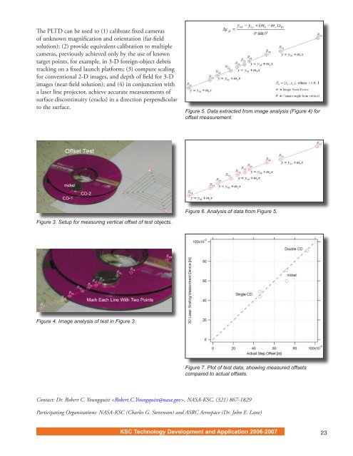
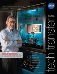
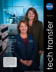
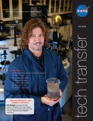
tracking objects after launch, and