ECE-320 CH02.pdf - Unix.eng.ua.edu
ECE-320 CH02.pdf - Unix.eng.ua.edu
ECE-320 CH02.pdf - Unix.eng.ua.edu
- No tags were found...

You also want an ePaper? Increase the reach of your titles
YUMPU automatically turns print PDFs into web optimized ePapers that Google loves.
G. Rizzoni, Principles and Applications of Electrical Engineering Problem solutions, Chapter 2Chapter 2 Instructor NotesChapter 2 develops the foundations for the first part of the book. Coverage of the entire Chapter would betypical in an introductory course. The first four sections provide the basic definitions and cover Kirchoff’sLaws and the passive sign convention; the box Focus on Methodology: The Passive Sign Convention (p.35) and two examples illustrate the latter topic. The sidebars Make The Connection: Mechanical Analog ofVoltage Sources (p. 20) and Make The Connection: Hydraulic Analog of Current Sources (p. 22) presentthe concept of analogies between electrical and other physical domains; these analogies will continuethrough the first six chapters.Sections 2.5and 2.6 introduce the i-v characteristic and the resistance element. Tables 2.1 and 2.2 on p. 41summarize the resistivity of common materials and standard resistor values; Table 2.3 on p. 44 provides theresistance of copper wire for various gauges. The sidebar Make The Connection: Electric Circuit Analog ofHydraulic Systems – Fluid Resistance (p. 40) continues the electric-hydraulic system analogy.Finally, Sections 2.7 and 2.8 introduce some basic but important concepts related to ideal and nonidealcurrent sources, and measuring instruments.The Instructor will find that although the material in Chapter 2 is quite basic, it is possible to givean applied flavor to the subject matter by emphasizing a few selected topics in the examples presented inclass. In particular, a lecture could be devoted to resistance devices, including the resistive displacementtransducer of Focus on Measurements: Resistive throttle position sensor (pp. 52-54), the resistance straingauges of Focus on Measurements: Resistance strain gauges (pp. 54-55), and Focus on Measurements:The Wheatstone bridge and force measurements (pp. 55-56). The instructor wishing to gain a more in-depthunderstanding of resistance strain gauges will find a detailed analysis in 1 .Early motivation for the application of circuit analysis to problems of practical interest to the nonelectrical<strong>eng</strong>ineer can be found in the Focus on Measurements: The Wheatstone bridge and forcemeasurements. The Wheatstone bridge material can also serve as an introduction to a laboratoryexperiment on strain gauges and the measurement of force (see, for example 2 ). Finally, the material onpractical measuring instruments in Section2.8b can also motivate a number of useful examples.The homework problems include a variety of practical examples, with emphasis oninstrumentation. Problem 2.36 illustrates analysis related to fuses; problems 2.44-47 are related to wiregauges; problem 2.52 discusses the thermistor; problems 2.54 and 2.55 discuss moving coil meters;problems 2.52 and 2.53 illustrate calculations related to temperature sensors; an problems 2.56-66 present avariety of problems related to practical measuring devices.It has been the author's experience that providing the students with an early introduction topractical applications of electrical <strong>eng</strong>ineering to their own disciplines can increase the interest level in thecourse significantly.Learning Objectives1. Identify the principal elements of electrical circuits: nodes, loops, meshes, branches,and voltage and current sources.2. Apply Kirchhoff’s Laws to simple electrical circuits and derive the basic circuiteq<strong>ua</strong>tions.3. Apply the passive sign convention and compute power dissipated by circuit elements.4. Apply the voltage and current divider laws to calculate unknown variables in simpleseries, parallel and series-parallel circuits.5. Understand the rules for connecting electrical measuring instruments to electricalcircuits for the measurement of voltage, current, and power.1 E. O. Doebelin, Measurement Systems – Application and Design, 4 th Edition, McGraw-Hill, New York,1990.2 G. Rizzoni, A Practical Introduction to Electronic Instrumentation, 3 rd Edition, Kendall-Hunt, 1998.2.1
G. Rizzoni, Principles and Applications of Electrical Engineering Problem solutions, Chapter 2Analysis:Joule JVoltage = Volt = V =Coulomb CCoulomb CCurrent = Ampere =a =second sVolt Joule×secondResistance = Ohm = =Ω =2Ampere Coulomb2Ampere CConductance = Siemen or Mho = =Volt J ⋅ sJ ⋅ s2C________________________________________________________________________Solution:Problem 2.3Known q<strong>ua</strong>ntities:Battery nominal rate of 100 A-h.Find:a) Charge potentially derived from the batteryb) Electrons contained in that charge.Assumptions:Battery fully charged.Analysis:a)b) C 100A×1hr= 100 s = 360000 Ccharge on electron:( 1hr)3600− 1.602 × 10⁻¹⁹shrCno. of electrons =3360×10 C191.602×10− C= 224.7×10²²________________________________________________________________________Solution:Problem 2.4Known q<strong>ua</strong>ntities:Two-rate change charge cycle shown in Figure P2.4.2.3
G. Rizzoni, Principles and Applications of Electrical Engineering Problem solutions, Chapter 2Find:a) The charge transferred to the batteryb) The energy transferred to the battery.Analysis:a) To find the charge delivered to the battery during the charge cycle, we examine the charge-currentrelationship:thus:i =dqdttor1Q = i () t dtt05hrsdq = i ⋅ dt10hrsQ = 50mAdt + 20mAdt018000s5hrs36000s= 005 . dt + 002 . dt018000= 900 + 360= 1260Cb) To find the energy transferred to the battery, we examine the energy relationshipdwp = or dw = p(t)dtdtt1w = p(t)dt =t0tt10v(t)i(t)dtobserving that the energy delivered to the battery is the integral of the power over the charge cycle. Thus,180000= (0.05t +0.7536000t2)180000360000.75tw = 0.05(1+ ) dt +18000180000.02(1++ (0.02t +0.25360000.25t) dt18000t2)3600018000w =1732.5 J________________________________________________________________________Solution:Problem 2.5Known q<strong>ua</strong>ntities:Rated voltage of the battery; rated capacity of the battery.Find:a) The rated chemical energy stored in the batteryb) The total charge that can be supplied at the rated voltage.2.4
G. Rizzoni, Principles and Applications of Electrical Engineering Problem solutions, Chapter 2Analysis:a)∆PEc∆Q∆ V ≡ I =∆Q∆tChemical energy = ∆PE= ∆V⋅ ∆Q= ∆V⋅( I ⋅ ∆t)= 12 V 350 a hr 3600= 15.12 MJ.cshrAs the battery discharges, the voltage will decrease below the rated voltage. The remaining chemicalenergy stored in the battery is less useful or not useful.b) ∆ Q is the total charge passing through the battery and gaining 12 J/C of electrical energy.∆Q= I ⋅ ∆t= 350 a hr = 350= 1.26 MC.Cshr ⋅ 3600________________________________________________________________________Solution:Problem 2.6shrKnown q<strong>ua</strong>ntities:Resistance of external circuit.Find:a) Current supplied by an ideal voltage sourceb) Voltage supplied by an ideal current source.Assumptions:Ideal voltage and current sources.Analysis:a) An ideal voltage source produces a constant voltage at or below its rated current. Current is determinedby the power required by the external circuit (modeled as R).VsI =RP = Vs⋅ Ib) An ideal current source produces a constant current at or below its rated voltage. Voltage is determinedby the power demanded by the external circuit (modeled as R).V = I⋅ RP = V ⋅sI sA real source will overheat and, perhaps, burn up if its rated power is exceeded.________________________________________________________________________2.5
G. Rizzoni, Principles and Applications of Electrical Engineering Problem solutions, Chapter 2Sections 2.2, 2.3: KCL, KVLSolution:Problem 2.7Known q<strong>ua</strong>ntities:Circuit shown in Figure P2.7 with currents −2V S= 12 V.Find:The unknown currents.Analysis:Applying KCL to node (a) and node (b):I 0= A, = −4A, I S= 8I 1A, and voltage sourceII00+ I1+ IS+ I2+ I1= 0− I3= 0I I23= −(I= I00+ I+ IS1) = 6 A+ I1= 2 A________________________________________________________________________2.6
G. Rizzoni, Principles and Applications of Electrical Engineering Problem solutions, Chapter 2Section 2.4: Sign ConventionFocus on Methodology: Passive Sign Convention1. Choose an arbitrary direction of current flow.2. Label polarities of all active elements (current and voltage sources).3. Assign polarities to all passive elements (resistors and other loads); for passive elements,current always flows into the positive terminal.4. Compute the power dissipated by each element according to the following rule: If positivecurrent flows into the positive terminal of an element, then the power dissipated ispositive (i.e., the element absorbs power); if the current leaves the positive terminal of anelement, then the power dissipated is negative (i.e., the element delivers power).Solution:Problem 2.8Known q<strong>ua</strong>ntities:Direction and magnitude of the current through the elements in Figure P2.8; voltage at the terminals.Find:Class of the components A and B.Analysis:The current enters the negative terminal of element B and leaves the positive terminal: its coulombicpotential energy increases.Element B is a power source. It must be either a voltage source or a current source.The reverse is true for element A. The current loses energy as it flows through element A.Element A could be 1. a resistor or 2. a power source through which current is being forced to flows‘backwards’.________________________________________________________________________Solution:Problem 2.9Known q<strong>ua</strong>ntities:Current absorbed by the heater; voltage at which the current is supplied; cost of the energy.Find:a) Power consumptionb) Energy dissipated in 24 hr.c) Cost of the EnergyAssumptions:The heater works for 24 hours continuously.Analysis:a)2.7
G. Rizzoni, Principles and Applications of Electrical Engineering Problem solutions, Chapter 2J aP = VI = 110 V= 53a sb)( 23 a) = 2.53 K 2. KWJsW = Pt = 2 .53 K 24 hr 3600 = 218. 6 MJs hrc)centsCost = ( Rate)W = 6cents =KW hr( 2.53 KW )( 24 hr) = 364.3 $3. 64________________________________________________________________________Solution:Problem 2.10Known q<strong>ua</strong>ntities:Current through elements A, B and C shown in Figure P2.10; voltage across elements A, B and C.Find:Which components are absorbing power, which are supplying power; verify the conservation of power.Analysis:A absorbsB absorbsC supplies( 35 V )(15 A)= 525 W( 15 V )(15 A)= 225 W( 50 V )(15 A)= 750 W= P C= 750 W= PB + P = 225 W + 525 W = 750 WTotal power suppliedTotal power absorbedATotal power supplied = Total power absorbed, so conservation of power is satisfied.________________________________________________________________________Solution:Problem 2.11Known q<strong>ua</strong>ntities:Circuit shown in Figure P2.11 with voltage source,R s= 5 kΩ ; and resistance of the load, R L= 7 kΩ.V s= 12V; internal resistance of the source,Find:The terminal voltage of the source; the power supplied to the circuit, the efficiency of the circuit.Assumptions:Assume that the only loss is due to the internal resistance of the source.2.8
G. Rizzoni, Principles and Applications of Electrical Engineering Problem solutions, Chapter 2Analysis:KVL : −VS+ ITRS+ VT= 0VTOL : VT= ITRL∴ IT=RLVT−VS+ RS+ VT= 0RLVS12 VVSRL12 V 7 KΩVT= = = 7 V or VD : VT= == 7 V.RS5 KΩR R 5 K 7 K1 1S+LΩ + Ω+ +RL7 KΩ2 22VRVT( 7 V )PL = = = = 7 mWR R VL L7 Ka2P PoutR ITRL7 KΩLη = = === 0.5833 or 58.33% .2 2P P + P I R + I R 5 KΩ + 7 KΩinRSRLTS________________________________________________________________________Solution:Problem 2.12TLKnown q<strong>ua</strong>ntities:Circuit shown in Figure P2.12; Current through elements D and E; voltage across elements B, C and E.Find:a) Which components are absorbing power and which are supplying powerb) Verify the conservation of power.Analysis:a)By KCL, the current through element B is 5 A, to the right. By KVL,v = v = V (positive at the top)D E10vA+ 5 −10−10= 0Therefore the voltage across element A isv A= 15 V (positive on top)A suppliesB suppliesC absorbsD absorbsE absorbsb)( 15 V )(5 A)= 75 W( 5 V )(5 A)= 25 W( 10 V )(5 A)= 50 W( 10 V )(4 A)= 40 W( 10 V )(1 A)= 10 WTotal power supplied= PA + PB= 75 W + 25 W = 100W2.9
G. Rizzoni, Principles and Applications of Electrical Engineering Problem solutions, Chapter 2= PC + P + P = 50 W + 40 W + 10 W = 100 WTotal power absorbedD ETotal power supplied = Total power absorbed, so conservation of power is satisfied.________________________________________________________________________Solution:Problem 2.13Known q<strong>ua</strong>ntities:Headlights connected in parallel to a 24-V automotive battery; power absorbed by each headlight.Find:Resistance of each headlight; total resistance seen by the battery.Analysis:Headlight no. 1:Headlight no. 2:2vP = v×i = 100 W = orR2v 576R = = = 5.76Ω100 1002vP = v×i = 75 W = orR2v 576R = = = 7.68Ω75 75The total resistance is given by the parallel combination:1R TOTAL1 1= +5.76Ω7.68Ωor RTOTAL = 3.29 Ω________________________________________________________________________Solution:Problem 2.14Known q<strong>ua</strong>ntities:Headlights and 24-V automotive battery of problem 2.13 with 2 15-W taillights added in parallel; powerabsorbed by each headlight; power absorbed by each taillight.Find:Equivalent resistance seen by the battery.Analysis:The resistance corresponding to a 75-W headlight is:R75W2v 576= = = 7.68Ω75 75For each 15-W tail light we compute the resistance:2.10
G. Rizzoni, Principles and Applications of Electrical Engineering Problem solutions, Chapter 2R15W2v 576= = = 38.4Ω15 15Therefore, the total resistance is computed as:1R TOTAL1 1 1 1= + + +7.68Ω7.68Ω38.4Ω38.4ΩorRTOTAL= 3.2 Ω________________________________________________________________________Solution:Problem 2.15Known q<strong>ua</strong>ntities:Circuit shown in Figure P2.15 with voltage source,= ; and resistor, = 5ΩV s20VFind:The power absorbed by variable resistor R (ranging from 0 to 20 Ω).Analysis:The current flowing clockwise in the series circuit is:20i = 5 + RThe voltage across the variable resistor R, positive on the left, is:Therefore,v R20R= Ri =R + 5PR 20 = vRi= R 5 + R2R .o________________________________________________________________________2.11
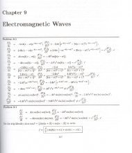
G. Rizzoni, Principles and Applications of Electrical Engineering Problem solutions, Chapter 2Solution:Problem 2.16Known q<strong>ua</strong>ntities:Circuit shown in Figure P2.16 with source voltage,R = 0. 3Ω . Current, =sI 0, 5, 10, 20, 30 A.TV s= 12V; internal resistance of the source,Find:a) The power supplied by the ideal source as a function of currentb) The power dissipated by the nonideal source as a function of currentc) The power supplied by the source to the circuitd) Plot the terminal voltage and power supplied to the circuit as a function of currentAssumptions:There are no other losses except that on Rs.Analysis:a) Ps = power supplied by the source = VSIS= VSIT.b) Rs = equivalent resistance for internal lossesPloss= I2TRc) VT= voltage at the battery terminals:VD :VTS= VS− RP0= power supplied to the circuit ( RLin this case)Conservation of energy:P = P .S loss+ P 0SIT= I TVT.I T(A) P S(W ) P loss(W ) V T(V ) P ( )0W0 0 0 0 02 30 1.875 11.4 28.135 60 7.5 10.5 52.510 120 30 9 9020 240 120 6 12030 360 270 3 902.12
G. Rizzoni, Principles and Applications of Electrical Engineering Problem solutions, Chapter 212Terminal Voltage11109V t(V)8765430 5 10 15 20 25 30I t(A)400350300P(W)250200150Pi=PsP01005000 5 10 15 20 25 30It(a)Note that the power supplied to the circuit is maximum whenRRLSP=IP=IRL02Tloss2T= R120 Va= = 302(20 a)S120 Va=2(20 a)Vma= 30 mΩ= 30 mΩI T= 20a.________________________________________________________________________2.13
G. Rizzoni, Principles and Applications of Electrical Engineering Problem solutions, Chapter 2Solution:Problem 2.17Known q<strong>ua</strong>ntities:Circuit shown in Figure P2.17 if the power delivered by the source is 40 mW; the voltage v = v1/4; andR = kΩ,R = 10kΩ,R = 12kΩ1823Find:The resistance R, the current i and the two voltages v and v1Analysis:P = v ⋅i= 40 mW (eq. 1)vv1 = R2⋅i= 10000⋅i= (eq. 2)4From eq.1 and eq.2, we obtain:i = 1.0 mA and v = 40 V.Applying KVL for the loop:− v + 8000 i + 10000i+ Ri + 12000i= 0 or, 0 .001R= 10Therefore,R = 10kΩ and v 1= 10V.________________________________________________________________________Solution:Problem 2.18Known q<strong>ua</strong>ntities:Rated power; rated optical power; operating life; rated operating voltage; open-circuit resistance of thefilament.Find:a) The resistance of the filament in operationb) The efficiency of the bulb.Analysis:a)P = VIOL:PR∴ I =VR60 Va= = 521.7 ma115 VV VR115 VR = = = = 220. 4 ΩI I 521.7 mab)Efficiency is defined as the ratio of the useful power dissipated by or supplied by the load to the total powersupplied by the source. In this case, the useful power supplied by the load is the optical power. From anyhandbook containing equivalent units: 680 lumens=1 W2.14
G. Rizzoni, Principles and Applications of Electrical Engineering Problem solutions, Chapter 2WPo , out= Optical Power Out = 820 lum = 1. 206 W680 lumPo, out 1.206 Wη = efficiency = = = 0.02009 = 2.009 %P 60 WR________________________________________________________________________Solution:Problem 2.19Known q<strong>ua</strong>ntities:Rated power; rated voltage of a light bulb.Find:The power dissipated by a series of three light bulbs connected to the nominal voltage.Assumptions:The resistance of each bulb doesn’t vary when connected in series.Analysis:When connected in series, the voltage of the source will divide eq<strong>ua</strong>lly across the three bulbs. The acrosseach bulb will be 1/3 what it was when the bulbs were connected individ<strong>ua</strong>lly across the source. Powerdissipated in a resistance is a function of the voltage sq<strong>ua</strong>red, so the power dissipated in each bulb whenconnected in series will be 1/9 what it was when the bulbs were connected individ<strong>ua</strong>lly, or 11.11 W:Ohm’s Law:P = IVVB = VS= 110 VRBB( 110 V )= I2R2VB= = = 121 ΩP 100 Va2BV=R2BBConnected in series and assuming the resistance of each bulb remains the same as when connectedindivid<strong>ua</strong>lly:KVL: −VS+ VB1+ VB2+ VB3= 0OL: −V+ IR + IR + IR 0SB3 B2B1=VS 110 VI === 303maR R RVB1+B2+B3121+121+121a22 V 1PB = I RB1= 303 ma 121 = 11.11W= 100 a 9( ) .1W________________________________________________________________________Solution:Problem 2.20Known q<strong>ua</strong>ntities:Rated power and rated voltage of the two light bulbs..2.15
G. Rizzoni, Principles and Applications of Electrical Engineering Problem solutions, Chapter 2Find:The power dissipated by the series of the two light bulbs.Assumptions:The resistance of each bulb doesn’t vary when connected in series.Analysis:When connected in series, the voltage of the source will divide eq<strong>ua</strong>lly across the three bulbs. The acrosseach bulb will be 1/3 what it was when the bulbs were connected individ<strong>ua</strong>lly across the source. Powerdissipated in a resistance is a function of the voltage sq<strong>ua</strong>red, so the power dissipated in each bulb whenconnected in series will be 1/9 what it was when the bulbs were connected individ<strong>ua</strong>lly, or 11.11 W:Ohm’s Law:P = IVVB = VS= 110 VRR60100B( 110 V )= I2RBV=R2B2VB= = = 201. 7 ΩP 60 Va602( 110 V )2VB= = = 121 ΩP 100 Va1002BWhen connected in series and assuming the resistance of each bulb remains the same as when connectedindivid<strong>ua</strong>lly:KVL: −VS+ VB60 + VB100= 0OL: −V+ IR + IR 0SB60 B100=VS110 VI === 340.9 maR RVB60+B100201.7 + 121a22 V PB 60= I RB60= 340.9 ma 201.7 = 23. 44 a 22 V PB 100= I RB100= 340.9 ma 121 = 14. 06 a ( ) W( ) WNotes: 1.It’s strange but it’s true that a 60 W bulb connected in series with a 100 W bulb will dissipatemore power than the 100 W bulb. 2. If the power dissipated by the filament in a bulb decreases, thetemperature at which the filament operates and therefore its resistance will decrease. This made theassumption about the resistance necessary.________________________________________________________________________Solution:Problem 2.21Known q<strong>ua</strong>ntities:Schematic of the circuit shown in Figure P2.21.Find:The resistor values, including the power rating, necessary to achieve the indicated voltages for:a) V = 30V, R1 = 10kΩ,vout = 10V2.16
G. Rizzoni, Principles and Applications of Electrical Engineering Problem solutions, Chapter 2b) V = 12V, R1 = 140kΩ,vout = 8. 5VAssumptions:Resistors are available in 18 - 14 - 12 -, and 1-W ratings.Analysis:(a)(b) R 2R2v out= VR R ⋅ =⋅(30)= 10 2+1 R2+100003R2(30 −10)= 10⋅10⋅10R2= 5 kΩ22 30 P2= I R = ⋅(5000)= 20 mW15000P = 1R8 W22P = I R 40 mW1 1=1R 1= W .P8 R 140 2v ⋅out= V = 12⋅ = 8.52 1140 R + R + R1R1= 57ΩV 12 V2I = == 61 ma P1= I R1= 212. 1 mWR + R 57 Ω + 140 Ω1 222= I R2=P 520. 9 mW1P R4 W1 =P = R12W________________________________________________________________________Solution:Problem 2.22Known q<strong>ua</strong>ntities:Schematic of the circuit shown in Figure P2.22 with resistances,voltages,V 110 V , vout = 64. 3V= .R o= .6kΩ,R = 4. 3kΩ12; andFind:The resistor values, including the power rating, necessary to achieve the indicated voltages.2.17
G. Rizzoni, Principles and Applications of Electrical Engineering Problem solutions, Chapter 2Assumptions:Resistors are available in 18 - ¼- ½-, and 1-W ratings.Analysis:R 4300 2v out=V = 110⋅= 64.30 1 2160014300R + R + R + R + R1= 1. 45kΩV110VI === 15 maR0+ R1+ R21600 Ω + 1450 Ω + 4300 Ω21P0 = I R0= 360 mW PR= W0221P1 = I R1= 326.25 mW PR= W122P2 = I R2= 967.5mW PR 2= 1 W________________________________________________________________________Solution:Problem 2.23Known q<strong>ua</strong>ntities:Schematic of the circuit shown in Figure P2.23 with source voltage,R o= Ω,R 1= 10Ω,R = 2Ω.82Find:a) The equivalent resistance seen by the sourceb) The current ic) The power delivered by the sourced) The voltages v1and v2e) The minimum power rating required for R1Analysis:a) The equivalent resistance seen by the source isR eqb) Applying KVL:= R + R + = 8 + 10 + 2 = 20Ω0 1R2V 24VV − Req i = 0 , therefore i = = = 1.2A20ΩR eqv = 24V; and resistances,c)P source= Vi = 24 V ⋅1.2A= 28. 8Wd) Applying Ohm's law:e)v = R i = 10Ω ⋅1.2A12 V , and v = R i = 2Ω⋅1.2A2. 4 V1 1=2 2=2.18
G. Rizzoni, Principles and Applications of Electrical Engineering Problem solutions, Chapter 22( 1.2A) 14. W2P1 = R1i= 10Ω⋅= 4 , therefore the minimum power rating for R1is 16 W.________________________________________________________________________Solution:Problem 2.24Known q<strong>ua</strong>ntities:Schematic of the circuit shown in Figure P2.24 with resistors,R = Ω,R = 10Ω,R = 5Ω,= 7Ω.252341RFind:a) The currents i 1and i2b) The power delivered by the 3-A current source and the 12-V voltage sourcec) The total power dissipated by the circuit.Analysis:a) KCL at node 1 requires that:v 1R 2+v 1Solving for v1we haveTherefore,-12 VR3( 4 + R )- 3 A = 03R2v1= 3 = 18 VR + R2v118i1= − = − = −1.8 AR21012 − v16i2= = − = −1.2 AR 53b) The power delivered by the 3-A source is:P3-A = (v3-A)(3)3Thus, we can compute the voltage across the 3-A source asv3-A = R + v = 3⋅25 + 18 93 VThus,31 1=P3-A = (93)(3) = 279 W.Similarly, the power supplied by the 12-V source is:P12-V = (12)(I12-V)We have I12-V =12R4+ i 2= 514.3 mA, thus:P12-V = (12)(I12-V) = 6.17 Wc) Since the power dissipated eq<strong>ua</strong>ls the total power supplied:2.19
G. Rizzoni, Principles and Applications of Electrical Engineering Problem solutions, Chapter 2Pdiss = P3-A + P12-V =279 + 6.17 = 285.17 W________________________________________________________________________Solution:Problem 2.25Known q<strong>ua</strong>ntities:Schematic of the circuit shown in Figure P2.25.Find:The power delivered by the dependent source.Analysis:24V24i = = A = 2 A(7 + 5) Ω 12i source= 0.5i2= 0.5⋅( 4) = 2 AThe voltage across the dependent source (+ ref. taken at the top) can be found by KVL:− v D+ ( 2A)(15Ω)+ 24V= 0 = 54v VTherefore, the power delivered by the dependent source isPD= vDisource= 54 ⋅2= 108 W.________________________________________________________________________Solution:Problem 2.26DKnown q<strong>ua</strong>ntities:Schematic of the circuit in Figure P2.26.Find:a) If V1= 12.0V, R1= 0.15Ω,RL= 2. 55Ω, the load current and the power dissipated by theloadb) If a second battery is connected in parallel with battery 1with V2= 12.0V, R2= 0. 28Ω,determine the variations in the load current and in the power dissipated by the load due to theparallel connection with a second battery.Analysis:a)ILPV=R + RLoad112=0.15 + 2.551=2LL= I R = 50.4 W.L122.7= 4.44 Ab) with another source in the circuit we must find the new power dissipated by the load. To do so, we writeKVL twice using mesh currents to obtain 2 eq<strong>ua</strong>tions in 2 unknowns:2.20
G. Rizzoni, Principles and Applications of Electrical Engineering Problem solutions, Chapter 2I−V( I1+ I2)+ V− I22=2R21 2 1R10R + I RL= VSolving the above eq<strong>ua</strong>tions gives us:20.28⋅I2.55⋅2− 0.15⋅I( I + I )I1= 2.95 A, I2=1. 58 A = I1 + I2= 4. 532P I R = 52.33 WLoad=L L1I LA21= 0+ 0.28⋅I2= 12This is an increase of 1%.________________________________________________________________________Solution:Problem 2.27Known q<strong>ua</strong>ntities:Open-circuit voltage at the terminals of the power source is 50.8 V; voltage drop with a 10-W load attachedis to 49 V.Find:a) The voltage and the internal resistance of the sourceb) The voltage at its terminals with a 15-Ω load resistor attachedc) The current that can be derived from the source under short-circuit conditions.Analysis:(a)v s50. 8V(b)(c)(49V)RL2= 10W R = 240Ω= , the open-circuit voltageRRRSvL240= 49 50.8 = 49R + 240LSS+ RLS(240)(50.8)= − 240 = 8. 82Ω49Rv =R + RSv=15LS50.8 32. 0L8.82 + 15vS50.8( RL= 0) = = = 5.76R 8.82i ACCS________________________________________________________________________Solution:Problem 2.28=Known q<strong>ua</strong>ntities:Voltage of the heater, maximum and minimum power dissipation; number of coils, schematics of theconfigurations.V2.21
G. Rizzoni, Principles and Applications of Electrical Engineering Problem solutions, Chapter 2Find:a) The resistance of each coilb) The power dissipation of each of the other two possible arrangements.Analysis:(a) For the parallel connection, P = 2000 W. Therefore,or,2000 =1=1 1+ = R2( 220) ( 220)R12( 220) +R 1R225121R.For the series connection, P = 300 W. Therefore,or,( 220)12300 =R + R1R + RSolving, we find that122+1R2123= .484R = 131. 6Ωand = 29. 7Ω(b) the power dissipated by R 1 alone is:( 220)P R= = 368W1Rand the power dissipated by R 2 alone is( 220)P R= 1631W2R22= .121R .2________________________________________________________________________2.22
G. Rizzoni, Principles and Applications of Electrical Engineering Problem solutions, Chapter 2Section 2.5, 2.6: Resistance and Ohm’s LawSolution:Problem 2.29Known q<strong>ua</strong>ntities:Diameter of the cylindrical substrate; l<strong>eng</strong>th of the substrate; conductivity of the carbon.Find:The thickness of the carbon film required for a resistance R of 33 KΩ.Assumptions:Assume the thickness of the film to be much smaller than the radiusNeglect the end surface of the cylinder.Analysis:d dR = ≅σ ⋅ A σ ⋅ 2πa⋅ ∆td∆t= =R ⋅ 2πa⋅σ33⋅1039 ⋅10Ω ⋅ 2.9 ⋅106−3mS⋅m2π⋅1⋅10________________________________________________________________________Solution:Problem 2.30Known q<strong>ua</strong>ntities:The constants A and k; the open-circuit resistance.Find:The rated current at which the fuse blows, showing that this happens at:1I = .AkRAssumptions:Here the resistance of the fuse is given by:R = R0[ + A(T − )]01 T0where T0, room temperature, is assumed to be 25°C.We assume that:T T = kP− 0where P is the power dissipated by the resistor (fuse).Analysis:2R = R0 (1 + A⋅∆T) = R0(1 + AkP)= R0(1 + AkI R)2R − R AkI R =0R0−3m2.23
G. Rizzoni, Principles and Applications of Electrical Engineering Problem solutions, Chapter 2R02R = → ∞2 when I − R0 AkI → 01−R AkI01 1m ° C V −2I = = (0.7 0.35 0.11 ) =6.09 a.AkR ° C Va a0________________________________________________________________________Solution:Problem 2.31Known q<strong>ua</strong>ntities:Circuit shown in Figure P2.31 with voltage source,R .= 20Ω,R2= 40Ω,R3= 10Ω,R4= R5=6= 15Ω1RFind:The current in the 15-Ω resistors.Analysis:Since the 3 resistors must have eq<strong>ua</strong>l currents,and,I 15 ΩI =R1= ⋅ I31+ R210I 15=VS|| R + R34|| R5|| R6V s= 10Vand resistors,10 10= = = 30<strong>320</strong> + 8 + 5 33Therefore,Ω= 101 mA99________________________________________________________________________Solution:Problem 2.32Known q<strong>ua</strong>ntities:Schematic of the circuit in Figure P2.7 with currents −2V S= 12 V, and resistance = 2 ΩFind:R 0.The unknown resistances R1, R2, R3, R4and R5.I 0mA= A, = −4A, I S= 8I 1A, voltage sourceAssumption:In order to solve the problem we need to make further assumptions on the value of the resistors. For23example, we may assume that1R4= R and2R11R = .3Analysis:We can express each current in terms of the adjacent node voltages:2.24
G. Rizzoni, Principles and Applications of Electrical Engineering Problem solutions, Chapter 2IIIIIvR− vb+ Rva− v=22 + R3ab0= = −0 41v −= av bR1= −1v =v aR 12R314a2= =vR3= b =326VS− v 12 −= bv= bR RS=55Solving the system we obtain:82v = 3 V , v = 9 V , R 1= 1.5 Ω , R 2= 0.5 Ω , R 3= 4.5 Ω , R 4= 1ΩandaR 5= 0.375 Ω .b________________________________________________________________________Solution:Problem 2.33Known q<strong>ua</strong>ntities:Schematic of the circuit in Figure P2.7 with resistorsR 5= 3Ω , voltage source V S= 54 V, and current I 2= 4 A.Find:The unknown currents I0, I1, I3, ISand the resistor R0.R 1= 2Ω, = 5ΩAnalysis:We can express each current in terms of the adjacent node voltages:III01v −= av bR + R0va − v= bRvR212= a =44 v = 4 ⋅5= 20aVR 2, R 3= 4Ω, = 1ΩR 4,2.25
G. Rizzoni, Principles and Applications of Electrical Engineering Problem solutions, Chapter 2II3Sv b=R3VS− v= bRApplying KCL to node (a) and (b) :II00+ I1+ IS5+ I2+ I1= 0− ISolving the system we obtain:3= 020− vb20 − v+R0+ 1 220− vb54 − v+R0+ 1 3v = 24 V and = 1ΩbbbR 0.+ 4 = 020 − v+2bvb−4= 0________________________________________________________________________Solution:Problem 2.34Known q<strong>ua</strong>ntities:NOTE: Typo in Problem Statement for units of R 3Schematic of the circuit shown in Figure P2.34 with resistorsand voltage source V S= 12 V.Find:a) The mesh currents i a, i b, i cb) The current through each resistor.Analysis:Applying KVL to mesh (a), mesh (b) and mesh (c):iaR0+ ( ia− ib) R1= 0( ia− ib) R1− ibR2+ ( ic− ib)V = ( i − i ) RSSolving the system we obtain:iiiabcc= 2 A= 6 A= 8 Ab3IIIIRRRR0123= i= i= i= iabbc− i− iR= 2 Aa= 6 Ab3= 0= 4 A= 2 AR0212R3= Ω,R = 1Ω,R = 4 / 3Ω,= 6Ω2ia+ ( ia− ib) = 04( ia− ib) − ib+ 6( ic− ib)36( i − i ) = 12cb(positive in the direction of i(positive in the direction of i(positive in the direction of i(positive in the direction of iabbc= 0________________________________________________________________________))))2.26
G. Rizzoni, Principles and Applications of Electrical Engineering Problem solutions, Chapter 2Solution:Problem 2.35Known q<strong>ua</strong>ntities:NOTE: Typo in Problem Statement for units of R 3Schematic of the circuit shown in Figure P2.34 with resistorsand voltage source V S= 24 V.Find:a) The mesh currents i a, i b, i cb) The current through each resistor.Analysis:Applying KVL to mesh (a), mesh (b) and mesh (c):iaR0+ ( ia− ib) R1= 0( ia− ib) R1− ibR2+ ( ic− ib)V = ( i − i ) R S c b 3Solving the system we obtain:VR= R i0ia= 2 A VR= R1 1ib= 4 A ic= 10 A VR= R i2VR= R3 30 aR3= 0= 4 V( i − i )b2 b= 20 V( i − i )cab= 4 V224= 24 VR0212R3= Ω,R = 2Ω,R = 5Ω,= 4Ωia+ 2( ia− ib) = 0( ia− ib) − 5ib+ 4( ic− ib)( i − i ) = 24cb( ⊕ up)( ⊕ down)( ⊕ up)( ⊕ up)________________________________________________________________________Solution:Problem 2.36Known q<strong>ua</strong>ntities:NOTE: Typo in Problem Statement for units of R 3Schematic of the circuit shown in Figure P2.34 with resistorsand of the current source I S= 12 A.R= 00112R3= Ω,R = 3Ω,R = 2Ω,= 4ΩFind:The voltage across each resistance.Analysis:Applying KVL to mesh (a), mesh (b) and mesh (c):iaR0+ ( ia− ib) R1= 0( i − i ) R − i R + ( i − i )ica= IbS1b2cbR3= 0+ 3( ia− ib)( i − i ) − 2iia3a bic= 12 A= 0b− 4ib+ 48 = 02.27
G. Rizzoni, Principles and Applications of Electrical Engineering Problem solutions, Chapter 2Solving the system we obtain:iiiabc16= A364= A9= 12 AVVVVRRRR0123= R i= R1= R0 a= R i= 5.33 V( i − i )2 b3b= 14.22 V( i − i )cab= 5.33 V= 19.55 V( ⊕ up)( ⊕ down)( ⊕ up)( ⊕ up)________________________________________________________________________Solution:Problem 2.37Known q<strong>ua</strong>ntities:Schematic of voltage divider network shown of Figure P2.37.Find:a) The worst-case output voltages for ± 10 percent toleranceb) The worst-case output voltages for ± 5 percent toleranceAnalysis:a) 10% worst case: low voltageR2 = 4500 Ω, R1 = 5500 Ωv45004500 + 5500OUT , MIN=5 = 2. 2510% worst case: high voltageR2 = 5500 Ω, R1 = 4500 Ωv55004500 + 5500OUT , MAX=5 = 2. 75b) 5% worst case: low voltageR 2 = 4750 Ω, R 1 = 5250 Ωv47504750 + 5250OUT , MIN=5 = 2. 3755% worst case: high voltageR 2 = 5250 Ω, R 1 = 4750 Ωv52505250 + 4750OUT , MAX=5 = 2. 625________________________________________________________________________VVVV2.28
G. Rizzoni, Principles and Applications of Electrical Engineering Problem solutions, Chapter 2Solution:Problem 2.38Known q<strong>ua</strong>ntities:Schematic of the circuit shown in figure P2.38 withresistances, R = Ω,R = 12Ω,R = 8Ω,R = 2Ω,R = 16Ω,= 5Ω.041234R5Find:The equivalent resistance of the circuit.Analysis:Starting from the right side, we combine the two resistors in series:Then, we can combine the two parallel resistors, namely the 5 Ω resistor and 10 Ω resistor:R1 1parallel1 1= +5 10−10( Ω ) R = Ωparallel3Then, we can combine the two resistors in series, namely the 3.33 Ω and the 16 Ω resistor:Then, we can combine the two parallel resistors, namely the 12 Ω resistor and 19.33 Ω resistor:R1 1parallel1 1= +12 19.33−( Ω ) R = 7.4 Ωparallel2.29
G. Rizzoni, Principles and Applications of Electrical Engineering Problem solutions, Chapter 2Therefore, Req= 4 + 7.4 = 11.4 Ω._______________________________________________________________________Solution:Problem 2.39Known q<strong>ua</strong>ntities:Schematic of the circuit shown in Figure P2.39 with source voltage,V s12VR = Ω,R = 2Ω,R = 50Ω,R = 8Ω,R = 10Ω,R = 12Ω,= 6Ω.0412345R6Find:= ; and resistances,The equivalent resistance of the circuit seen by the source; the current i through the resistance R2.Analysis:Starting from the right side, we can combine the three parallel resistors, namely the 10 Ω resistor, the 12 Ωresistor and the 6 Ω resistor:R1 1parallel1 1 1= + +10 12 6−20( Ω ) R = Ωparallel7Then, we can combine the two resistors in series, namely the 8 Ω and the 2.86 Ω resistor:Then, we can combine the three parallel resistors, namely the 4 Ω resistor, the 50 Ω resistor and the 10.86Ω resistor:2.30
G. Rizzoni, Principles and Applications of Electrical Engineering Problem solutions, Chapter 2R1 1parallel=141 1+ +50 10.86−( Ω ) R = 2.76 ΩparallelTherefore, Req= 2 + 2.76 = 4.76 Ω.Looking at the following equivalent circuit:We can apply KVL and KCL to the above circuit:VS− 2I1− 4I0= 0I1= I0+ i + Ieq4I0= 50i= 2.86IeqI0= 12.5iI1= 6 − 25iIeq= 17.48ii= I1− I0− Ieq i = 107 mA________________________________________________________________________Solution:Problem 2.40Known q<strong>ua</strong>ntities:Schematic of the circuit shown in Figure P2.40 with source voltage,V s50V= ; resistances,R1= 20Ω,R2= 5Ω,R3= 2Ω,R4= 8Ω,R5= 8Ω,R6= 30Ω; and power absorbed by the 20-Ωresistor.Find:The resistance R .Analysis:Starting from the right side, we can replace resistors Ri(i=2..6) with a single equivalent resistors:R eq= R+( R + ( R R )) || = 10 Ω||5 62 3 4R2.31
G. Rizzoni, Principles and Applications of Electrical Engineering Problem solutions, Chapter 2The same voltage appears across both R1and Reqand, therefore, these element are in parallel. Applyingthe voltage divider rule:R1|| Req1000VR= V =1 SR + R || R 3R+ 20The power absorbed by the 20-Ω resistor is:P20Ω=1( V )12eq1 1000 = 20 3R+ 20 250000R1 = =R( 3R+ 20)220R = 10 Ω________________________________________________________________________Solution:Problem 2.41Known q<strong>ua</strong>ntities:Schematic of the circuit shown in Figure P2.41.Find:The equivalent resistance Reqof the infinite network of resistors.Analysis:We can see the infinite network of resistors as the equivalent to the circuit in the picture:R eqRRRR eqTherefore,ReqRReq= R + ( R || Req) + R = 2R+ R eq= ( 1+ 3)RR + Req________________________________________________________________________2.32
G. Rizzoni, Principles and Applications of Electrical Engineering Problem solutions, Chapter 2Solution:Problem 2.42Known q<strong>ua</strong>ntities:Schematic of the circuit shown in Figure P2.42 with source voltage,V s= 110V; and resistances,R .= 90Ω,R2= 50Ω,R3= 40Ω,R4= 20Ω,R5= 30Ω,R6= 10Ω,R7= 60Ω,8= 80Ω1RFind:a) The equivalent resistance of the circuit seen by the source.b) The current through and the power absorbed by the resistance 90-Ω resistance.Analysis:a) Starting from the right side, we can combine the two parallel resistors, namely the 20 Ω resistor and the30 Ω resistor:R1 1parallel=1201+30−( Ω ) R = 12 ΩparallelThen we can combine the two parallel resistors in the bottom, namely the 60 Ω resistor and the 80 Ω, andthe two resistor in series:R1 1parallel=1601+80−( Ω ) R = 34.3 ΩparallelThen we can combine the two parallel resistors on the right, namely the 40 Ω resistor and the 22 Ω:R1 1parallel=1401+22−( Ω ) R = 14.2 Ωparallel2.33
G. Rizzoni, Principles and Applications of Electrical Engineering Problem solutions, Chapter 2Therefore,1 1 11= +R 90eq( ) ( Ω −) R+ += 4750 14.2 34.3Ωeq.b) The current through and the power absorbed by the 90-Ω resistor are:IV110=90S90 Ω= =R1( V )1.22 A2110 2S90 Ω= = =R190P134.4 W________________________________________________________________________Solution:Problem 2.43Known q<strong>ua</strong>ntities:Schematic of the circuit shown in Figure P2.43.Find:The equivalent resistance at terminals a,b in the case that terminals c,d are a) open b) shorted; the same forterminals c,d with respect to terminals a,b.Analysis:With terminals c-d open, Req= ( 360 + 540) (180 + 540) Ω = 400Ω,with terminals c-d shorted, Req= ( 360 180) + (540 540) Ω = 390Ω,with terminals a-b open, Req= ( 540 + 540) (360 + 180) Ω = 360Ω,with terminals a-b shorted, Req= ( 360 540) + ( 180 540) Ω = 351Ω.________________________________________________________________________Solution:Problem 2.44Known q<strong>ua</strong>ntities:Layout of the site shown in Figure P2.44; characteristics of the cables; rated voltage of the generator; rangeof voltages and currents absorbed by the <strong>eng</strong>ine at full load.Find:The minimum AWG gauge conductors which must be used in a rubber insulated cable.2.34
G. Rizzoni, Principles and Applications of Electrical Engineering Problem solutions, Chapter 2Analysis:The cable must meet two requirements:1. The conductor current rating must be greater than the rated current of the motor at full load. Thisrequires AWG #14.2. The voltage drop due to the cable resistance must not r<strong>edu</strong>ce the motor voltage below its minimumrated voltage at full load.KVL :R−VR−V+ I+ R110 V −105V=7.103 AMaxGC1RC=dGC 2+ VM −FL1RV=RC1C1GRC=d2−VI+ V+ VM −MinM −FLM −MinM −Min+ V+ I= 703.9 mΩ=12=[ 703.9 mΩ]150 mRC 2M −FL= 0RC 2= 0Ω= 2.346 mmTherefore, AWG #8 or larger wire must be used.________________________________________________________________________Solution:Problem 2.45Known q<strong>ua</strong>ntities:Layout of the building shown in Figure P2.45; characteristics of the cables; rated voltage of the generator;total electrical load in the building.Find:The minimum AWG gauge conductors which must be used in a rubber insulated cable.Analysis:The cable must meet two requirements:1. The conductor current rating must be greater than the rated current of the motor at full load. Thisrequires AWG #4.2. The voltage drop due to the cable resistance must not r<strong>edu</strong>ce the motor voltage below its minimumrated voltage at full load.KVL :R−VR−V+ I+ R450 V − 446 V=51.57 AMaxSC1RC=dSL−FLC 21+ VRC1V=RC1SRC=d2+ V−VI+ VL−FL=L−MinL−MinL−Min+ V+ I== 77.6 mΩ12[ 77.6 mΩ]85 mRC 2L−FLR= 0C 2= 0Ω= 0.4565 mmTherefore, AWG #0 or larger wire must be used.________________________________________________________________________2.35
G. Rizzoni, Principles and Applications of Electrical Engineering Problem solutions, Chapter 2Solution:Problem 2.46Known q<strong>ua</strong>ntities:Layout of the site shown in Figure P2.46; characteristics of the cables; rated voltage of the generator;electrical characteristics of the <strong>eng</strong>ine.Find:The maximum l<strong>eng</strong>th of a rubber insulated cable with AWG #14 which can be used to connect the motorand the generator.Analysis:The voltage drop due to the cable resistance must not r<strong>edu</strong>ce the motor voltage below its minimum ratedvoltage at full load.KVL :d−VR−V+ I+ R+ VRV=110 V −105V=7.103 AMaxGC1R=RGM −FLC 2C1ratedRC1C1G−VIR=R+ V+ VC 2ratedM −MinM −FLM −MinM −Min+ V+ I== 703.9 mΩRC 2M −FL= 0R1= 2Ω8.285 mm[ 703.9 mΩ]C 2= 0= 42.48 m________________________________________________________________________Solution:Problem 2.47Known q<strong>ua</strong>ntities:Layout of the building shown in Figure P2.47; characteristics of the cables; rated voltage of the generator;total electrical load in the building.Find:The maximum l<strong>eng</strong>th of a rubber insulated cable with AWG #4 which can be used to connect the source tothe load.Analysis:The voltage drop due to the cable resistance must not r<strong>edu</strong>ce the motor voltage below its minimum ratedvoltage at full load.2.36
G. Rizzoni, Principles and Applications of Electrical Engineering Problem solutions, Chapter 2KVL :d−VR−V+ I+ R+ VRV=450 V − 446 V=51.57 AMaxSC1R=RSL−FLC 2C1ratedRC1C1S+ V−VIR=RC 2rated+ VL−FLL−MinL−MinL−Min+ V+ I== 77.6 mΩRC 2L−FLR1= 2Ω0.8153 mmC 2[ 77.6 mΩ]= 0= 0= 47.59 m________________________________________________________________________Solution:Problem 2.48Known q<strong>ua</strong>ntities:Schematic of the circuit shown in Figure P2.48 withresistances, R1 = 2.2kΩ,R2= 18kΩ, R = 220kΩ,R4= 3. 3kΩ3.Find:The equivalent resistance between A and B.Analysis:Shorting nodes C and D creates a single node to which all four resistors are connected.RRReq1eq2eq= R= R= R12eq1R3R1R3=R + R=[ 2.2 KΩ][ 4.7 KΩ]2.2 + 4.7 KΩ[ 18 KΩ][ 3.3 KΩ]= 1.499 KΩR2R4R4= == 2.789 KΩR2+ R418 + 3.3 KΩ+ R = 1.499 + 2.789 KΩ = 4.288 KΩeq213________________________________________________________________________Solution:Problem 2.49Known q<strong>ua</strong>ntities:Schematic of the circuit shown in Figure P2.49 with source voltage,R1= 11kΩ,R2= 220kΩ,R3= 6.8kΩ,R4= 0. 22mΩFind:The voltage between nodes A and B.V s= 12V; and resistances,2.37
G. Rizzoni, Principles and Applications of Electrical Engineering Problem solutions, Chapter 2Analysis:The same current flows through R1 and R3. Therefore, they are connected in series. Similarly, R2 and R4are connected in series.SPECIFY THE ASSUMED POLARITY OF THE VOLTAGE BETWEEN NODES A AND B. THISWILL HAVE TO BE A WILD GUESS AT THIS POINT.Specify the polarities of the voltage across R3 and R4 which will be determined using voltage division. Theact<strong>ua</strong>l polarities are not difficult to determine. Do so.VD :VD :KVL :VVR3R4VSR3=R1+ R3=VSR4=R + R=−VR32+ VAB4+ V[ 12 V ][ 6.8 kΩ]11+6.8 kΩ−6[ 12 V ][ 0.22×10 kΩ]−6( 220 + 0.22×10 ) kΩR4= 0∴VAB= V= 4.584 VR3−VR4= 1.20×10= 4.584VThe voltage is negative indicating that the polarity of VABis opposite of that specified.A solution is not complete unless the assumed positive direction of a current or assumed positive polarity ofa voltage IS SPECIFIED ON THE CIRCUIT.________________________________________________________________________Solution:Problem 2.50Known q<strong>ua</strong>ntities:Schematic of the circuit shown in Figure P2.49 with source voltage,R = .2kΩ,R = 18kΩ,R = 4.7kΩ,R = 3. 3kΩ12234−8V≈ 0V s= 5V; and resistances,Find:The voltage between nodes A and B.Analysis:The same current flows through R1 and R3. Therefore, they are connected in series. Similarly, R2 and R4are connected in series.SPECIFY THE ASSUMED POLARITY OF THE VOLTAGE BETWEEN NODES A AND B. THISWILL HAVE TO BE A WILD GUESS AT THIS POINT.Specify the polarities of the voltage across R3 and R4 which will be determined using voltage division. Theact<strong>ua</strong>l polarities are not difficult to determine. Do so.VD :VD :KVL :VR3VSR3=R + R[ 5V][ 4.7 KΩ]== 3.406V2.2KΩ + 4.7 KΩ[ 5V][ 3.3 KΩ]VSR4VR4= == 0.917 VR2+ R418KΩ + 3.3 KΩ−V+ V + V = 0 V = V −V= 2.489VR31AB3R4ABA solution is not complete unless the assumed positive direction of a current or assumed positive polarity ofa voltage IS SPECIFIED ON THE CIRCUIT.________________________________________________________________________R3R42.38
G. Rizzoni, Principles and Applications of Electrical Engineering Problem solutions, Chapter 2Solution:Problem 2.51Known q<strong>ua</strong>ntities:Schematic of the circuit shown in Figure P2.51 with source voltage,R = .7mΩ,R = 3kΩ,R = 10kΩ1123Find:The voltage across the resistance R3.V s= 12V; and resistances,Analysis:The same voltage appears across both R2and R3and, therefore, these element are in parallel. Applyingthe voltage divider rule:VR3R2|| R3=VR + R || R123R1
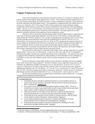
G. Rizzoni, Principles and Applications of Electrical Engineering Problem solutions, Chapter 2Sections 2.7, 2.8: Practical Sources and Measuring DevicesSolution:Problem 2.52Known q<strong>ua</strong>ntities:Parameters R0= 300 Ω (resistance at temperature T0= 298 K), andsecond resistor.Find:-1β = −0.01K , value of thea) Plot R th(T ) versus T in the range 350 T 750[°K]b) The equivalent resistance of the parallel connection with the 250-Ω resistor; plot R eq(T ) versusT in the range 350 T 750[°K] for this case on the same plot as part a.Assumptions:−β( T −T0)R ( T ) = R e .Analysis:a)b)RRthth( T ) = 300e0−0.01⋅( T −298)1500 e5 + 6 e( T −298)( 298)−0.01eq( T)= Rth( T)|| 250Ω =−0.01T −The two plots are shown below.In the above plot, the solid line is for the thermistor alone; the dashed line is for the thermistor-resistorcombination.________________________________________________________________________2.40
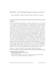
G. Rizzoni, Principles and Applications of Electrical Engineering Problem solutions, Chapter 2Solution:Problem 2.53Known q<strong>ua</strong>ntities:A potentiometer shown in the circuit of Figure P.253 with The value of the resistanceof the resistorFind:xTand voltage source vS.a) The expression for (x)b) The distance x when = 5 Vv out. Plot vout/ vSversus x / xT.vout.c) Assuming the resistance Rmbecomes infinite, repeat parts a and bAssumptions:Analysis:vva) v ( x)outoutSP=1( x x ) + ( R R )( 1−x x )TR ( x)= 200e=1xP110mT= 500x2 x3 x 2( x 0.02) + ( 200e100)( 1−x 0.02) 1−10e x + 5⋅10e xxRm, the total l<strong>eng</strong>thIn the above plot, the solid line is forxv outb) ( = 5 V) = 14.18 cmR = 100 Ω ; the dashed line is for → ∞mR .mc) Now R → ∞ .m2.41
G. Rizzoni, Principles and Applications of Electrical Engineering Problem solutions, Chapter 2vx( x)out=→ 500110x( x 0.02) + ( 200e∞)( 1−x 0.02)( = 5 V) = 10 cmv out________________________________________________________________________Solution:Problem 2.54Known q<strong>ua</strong>ntities:Meter resistance of the coil; meter current for full scale deflection; max measurable pressure.Find:a) The circuit required to indicate the pressure measured by a sensorb) The value of each component of the circuit; the linear rangec) The maximum pressure that can accurately be measured.Assumptions:Sensor characteristics follow what is shown in Figure P2.54Analysis:a) A series resistor to drop excess voltage is required.b) At full scale, meter:IrmFS ˆmˆ= 200Ω0. L.:= 10µAVmFS ˆ= ImFS ˆrmˆ= 2 mV.at full scale, sensor (from characteristics):P FS= 100V TFS= 9. 5kPamVKVL : −V+ V + V ˆ = 0VITFS RFS mFSRFS= VTFS−Vmˆ FS= 9.5 mV − 2 mV = 7. 5RFS= ITFS= Imˆ FS= 10µAOhm law:VRFS7.5 mVR = = = 750 ΩI 10 µ ARFSc) from sensor characteristic: 30 kPa –110 kPa.________________________________________________________________________Solution:Problem 2.55Known q<strong>ua</strong>ntities:Meter resistance of the coil; meter current for full scale deflection; max measurable pressure.Find:a) Redesign the circuit to meet the specification.b) The value of each component of the circuit.c) The linear range of the system..mVx2.42
G. Rizzoni, Principles and Applications of Electrical Engineering Problem solutions, Chapter 2Assumptions:Sensor characteristics follow what is shown in Figure P2.55Analysis:a) A series resistor to drop excess voltage is required.b) At full scale, meter:IrmFS ˆmˆ= 1.8kΩ0. L.:= 50µAVmFS ˆ= ImFS ˆrmˆ= 90 mV.at full scale, sensor (from characteristics):V TFS= 9. 5VKVL : −V+ V + V ˆ = 0VITFS RFS mFSRFS= VTFS−Vmˆ FS= 9.5 V − 90 mV = 9. 41RFS= ITFS= Imˆ FS= 50µAOhm law:VRFS 9.41VR = = = 188. 2 kΩI 50 µ ARFSc) from sensor characteristic: 20 kPa –110 kPa.________________________________________________________________________Solution:Problem 2.56Known q<strong>ua</strong>ntities:Meter resistance of the coil; meter voltage for full scale deflection; max measurable temperature.Find:a) The circuit required to meet the specifications of the new sensor.b) The value of each component of the circuit.c) The linear range of the system.Assumptions:Sensor characteristics follow what is shown in Figure P2.56Analysis:a) A parallel resistor is required to shunt (bypass) the excess current.b) At full scale, meter:VrmFS ˆmˆ= 2.5 kΩ0. L.:= 250 mVImFS ˆV=rmFS ˆmˆ= 100 µ A.at full scale, sensor (from characteristics):T FS= 400 °CI TFS= 8. 5mAKCL : − I + I + I ˆ = 0TFSRFSmFS.V2.43
G. Rizzoni, Principles and Applications of Electrical Engineering Problem solutions, Chapter 2IRFS= ITFS− Imˆ FS= 8.5 mA −100µ A = 8. 4 mAVRFS = VTFS= Vmˆ FS= 250 mVVRFS250 mVOhm law: R = = = 29. 76 Ω .I 8.4 mARFSc) from sensor characteristic: 220 °C –410 °C.________________________________________________________________________Solution:Problem 2.57Known q<strong>ua</strong>ntities:Meter resistance of the coil; meter voltage at full scale; max measurable temperature.Find:a) The circuit required to meet the specifications of the new sensor.b) The value of each component of the circuitc) The linear range of the system.Assumptions:Sensor characteristics follow what is shown in Figure P2.57Analysis:a) A parallel resistor is required to shunt (bypass) the excess current.b) At full scale, meter:VmFSˆ = 250 mVrmˆ = 2.5 kΩ0. L.:VmFSˆImFSˆ = = 100 µ A.rmˆat full scale, sensor (from characteristics):T FS= 400 °CI TFS= 8. 5 mAKCL : − ITFS+ IRFS+ Imˆ FS= 0IRFS= ITFS− Imˆ FS= 8.5 mA −100µ A = 8. 4 mAVRFS = VTFS= Vmˆ FS= 250 mVVRFS250 mVOhm law: R = = = 29. 76 Ω .I 8.4 mARFSc) from sensor characteristic: 220 °C –410 °C.________________________________________________________________________Solution:Problem 2.58Known q<strong>ua</strong>ntities:Schematic of the circuit shown in Figure P2.58; voltage at terminals with switch open and closed for freshbattery; same voltages for the same battery after 1 year.2.44
G. Rizzoni, Principles and Applications of Electrical Engineering Problem solutions, Chapter 2Find:The internal resistance of the battery in each case.Analysis:a)b)VrroutBB 10= 10+ rBVoc V oc = 10 −1 = 10Vout = 0.044Ω V oc = 10 −1 = 10Vout = 60.97Ω2.282.272.20.31−1−1________________________________________________________________________Solution:Problem 2.59Known q<strong>ua</strong>ntities:Ammeter shown in Figure P2.59; Current for full-scale deflection; desired full scale values.Find:Value of the resistors required for the given full scale ranges.Analysis:We desire R1, R2, R3 such that Ia = 30 µA for I = 10 mA, 100 mA, and 1 A, respectively. We useconductances to simplify the arithmetic:Ga =G1,2,3 =1 1=R a 10001R 1,2,3SBy the current divider rule:Ia =GaG + GaxIor:G G Ix=a IRx= Raa Ia I − I − Ga .aor1 1=G Gxa Ia I − Ia2.45
G. Rizzoni, Principles and Applications of Electrical Engineering Problem solutions, Chapter 2We can construct the following table:x I Rx (Approx.)1 10 -2 A 3 Ω2 10 -1 A 0.3 Ω3 10 0 A 0.03 Ω________________________________________________________________________Solution:Problem 2.60Known q<strong>ua</strong>ntities:Schematic of the circuit shown in Figure P2.60; for part b: value ofammeter.Find:The current i; the internal resistance of the meter.Assumptions:Analysis:r a
G. Rizzoni, Principles and Applications of Electrical Engineering Problem solutions, Chapter 2Find:The internal resistance of the voltmeter.Analysis:Using the voltage divider rule:r+ RmV = 11.81 = (12)rmsTherefore, rm= 1.55 MΩ.________________________________________________________________________Solution:Problem 2.62Known q<strong>ua</strong>ntities:Circuit shown in Figure P2.61 with source voltage,Find:The meter reads in the various cases.Analysis:By voltage division:rmV = (24)r + RmsV s= 24V; and ratios between Rsand rm.Rs0.2 r m0.4 r m0.6 r m1.2 r m4 r m6 r m10 rmV20 V17.14 V15 V10.91 V4.8 V3.43 V2.18 VFor a voltmeter, we always desire rm>> Rs .________________________________________________________________________Solution:Problem 2.63Known q<strong>ua</strong>ntities:Schematic of the circuit shown in Figure P2.63, values of the components.Find:The voltage across R4with and without the voltmeter for the following values:2.47
G. Rizzoni, Principles and Applications of Electrical Engineering Problem solutions, Chapter 2a) R4= 100Ωb) R4= 1kΩc) R4= 10kΩd) R = 100kΩ4.Assumptions:The voltmeter behavior is modeled as that of an ideal voltmeter in parallel with a 120- kΩ resistor.Analysis:We develop first an expression forTherefore,IIIV RS= I1 S RS+ R1+ R2|| R 2= I4 R1 R2+ R3+ R4RR= I RRRS+ R1 + R2||VR 4in terms of R4 . Next, using current division:( R + R )34 ⋅ ( R ) + + 3+ R4 R2R34 R 4 SRSR4= IR444 RSR4= IS RS+ R1+ R2||66000 ⋅ R4=6R + 2.1352⋅10Without the voltmeter:a)b)c)d)VR 4VR 4VR 4= 3.08 V= 30.47 V= 269.91 VVR 4= 1260.7 V.( R + R )34 ⋅ RNow we must find the voltage drop across R4with a 120-kΩ resistor across R4. This is the voltage thatthe voltmeter will read.IV= I RR122R2R+ R23+ RRS ⋅ R2|| 4( R) + + Ω 3+ ( R4||120kΩ R2R3( R ||120 ) R 4 S+ R + RkSR4= IR4= I ISS4 R= 82.57319RS+ R1+ R2|| ( R3+ ( R4||120kΩ)( 120000 + R ) ⋅ R44RSR44+ <strong>320</strong>.28⋅1064 ⋅ R2+ R3R2+ ( R4||120 )kΩ2.48
G. Rizzoni, Principles and Applications of Electrical Engineering Problem solutions, Chapter 2With the voltmeter:a)b)VR 4VR 4VR 4= 3.08 V= 30.47 Vc) = 272.57 Vd) VR 4= 1724.99 V.________________________________________________________________________Solution:Problem 2.64Known q<strong>ua</strong>ntities:Schematic of the circuit shown in Figure P2.64, value of the components.Find:The current through R5both with and without the ammeter, for the following values of the resistor R5:a) R5= 1kΩb) R5= 100Ωc) R5= 10Ωd) R = 1Ω.5Analysis:First we should find an expression for the current through R5in terms of R5and the meter resistance,Rm. By the voltage divider rule we have:VR 3=R3|| (R4+ R5+ RR || (R + R + R ) + R345m2m)VS+ (R1|| RS)andIR 3=R4V+ RR 35+ RmTherefore,IR 3=R3|| (R4+ R5+ Rm)VSR3|| (R4+ R5+ Rm) + R2+ (R5904=208350 + 373⋅(R+ R )mS1|| RS⋅) R41+ R5+ RmUsing the above eq<strong>ua</strong>tion will give us the following table:2.49
G. Rizzoni, Principles and Applications of Electrical Engineering Problem solutions, Chapter 2with meter incircuitwithout meterin circuita 10.15 mA 9.99 mAb 24.03 mA 23.15 mAc 27.84 mA 26.67 mAd 28.29 mA 27.08 mA________________________________________________________________________Solution:Problem 2.65Known q<strong>ua</strong>ntities:Schematic of the circuit and geometry of the beam shown in Figure P2.65, characteristics of the material,reads on the bridge.Find:The force applied on the beam.Assumptions:Gage Factor for Strain gauge is 2Analysis:R1 and R2 are in series; R3 and R4 are in series.VSR2VS( R0− ∆R)VS( R0− ∆R)Voltage Division: VR= ==2R + R R + ∆R+ R − ∆R2RVoltage Division:VKVL: − − + 0VRV13240VSR4VS( R0− ∆R)VS( R0+ ∆R)VR= ==4R + R R − ∆R+ R + ∆R2RV2 BA R=40VS( R + ∆R)VS( R0− ∆R)VS2∆RV= VR−VR=−= = VSGFε=4 22R2R2R0000( 2)( )LFwh Y0 S6BA 20002 0.050 V (0.025 m)(0.100m)V wh yF = =V 12L12 V 0.3 m( 12)69×10292BA m =sN19.97 kN.________________________________________________________________________Solution:Problem 2.66Known q<strong>ua</strong>ntities:Schematic of the circuit and geometry of the beam shown in Figure P2.65, characteristics of the material,reads on the bridge.Find:The force applied on the beam.2.50
G. Rizzoni, Principles and Applications of Electrical Engineering Problem solutions, Chapter 2Assumptions:Gage Factor for Strain gauge is 2Analysis:R1 and R2 are in series; R3 and R4 are in series.VSR2VS( R0− ∆R)VS( R0− ∆R)VD: VR= ==2R + R R + ∆R+ R − ∆R2RVD:13240VSR4VS( R0− ∆R)VS( R0+ ∆R)VR= ==4R + R R − ∆R+ R + ∆R2RVKVL: − − + 0RVV2 BA R=4000VS( R + ∆R)VS( R0− ∆R)VS2∆RVV = VR−VR=−= = VSGFε=4 22R02R02R029 N2 V (0.03 m)(0.07 m) 200×1026 V wh yBABAF = 1.3×10 N = =mV 12L24V12 1.7mV00( 2)( )LFwh y0 S6BA 2BA( )61.3×10 N × 24V12 1.7m=29 N(0.03 m)(0.07 m) 200×10ms2( )= 21.6V________________________________________________________________________2.51