GoldLine - Elterm
GoldLine - Elterm
GoldLine - Elterm
- No tags were found...

Create successful ePaper yourself
Turn your PDF publications into a flip-book with our unique Google optimized e-Paper software.
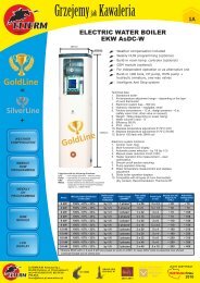
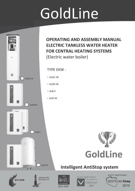
<strong>GoldLine</strong>rok założenia1992OPERATING AND ASSEMBLY MANUALELECTRIC TANKLESS WATER HEATERFOR CENTRAL HEATING SYSTEMS(Electric water boiler)TYPE EKW -AsDC-W- AsDC-W- AsZN-W- AsB II- AsD-WAsZN-WAsB II<strong>GoldLine</strong>AsD-WIntelligent AntiStop systemGRAND PRIXEKO-BUD '97ZŁOTY CERTYFIKATPRZEDSIĘBIORSTWOZŁOTY CERTYFIKATFAIR PLAY2001-2009 2001 2010
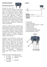
OFFOFF2Bolier EKW AsD-W10Tank diagram460 mm15 8 7 9 2Insulation (polistyren)CH hot water inflow18CirculationSensor coverCH water outflow11 Spiral coilThermostat sensor coverMagnesium anode.Cold water inflowSafety valve)HUW outflow3/4"L600 mm1/2"400 mm325 mm200 mm121/2"123456cc11:53:3312 05 2011 czw20100 mmLNet weight80 l 830 mm50 kgESCON100 l 975 mm53 kgBoiler EKW AsDC-WRETURN RETURN SUPPLY14 17 21 19 13 16 5 4 354 cmMin. Premises height 2,1m(required while installation)VENTMANOMETER 4 BARBoiler EKW AsDC-WWith build-in HUW tank- exemplary applicationCONTROL PANEL1234 56cc11:53 :33 12 0 5 20 11 czwESCONINSIDE BOILER:- CH PUMP- HUW PUMP- 8l CH MEMBRANE VESSEL- 2X ONE-WAY VALVE100l HUW TANK20circulationHUWoutflowCold wateroutflowCH.CHCOIL 29 kWSafetyvalveBallvalvemanometercirculationpumpmembranevesselMAGNESIUM ANODE
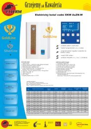
OFFOFF3Boiler EKW AsZN-W1015 8 7 9 2654321RELAYSEXTERNALREGULATORS1811ESC ONOFFATTENTIONTHERMOREGULATOR0 V!SENSORSSENSORSELTERMBODY. BAL. CH. HUW. ROOM. WEA..6123456cc11:53:3312 05 2011 czwESCON121BOILER EQUIPMENTExternal casing24 22 23EKWAsBIIyEKW EKW EKWAsZN . AsDC AsD-W -W -WEKWy y y2Mounting plateyyyy3Automatics mounting bracketsyyyyRETURN SUPPLY 4LCD displayyyyy14 17 13 16 5 4 35Control panelyyyy6Room thermostat connection stripyBoiler EKW AsB II7Boiler body (tank)y108Boiler insulationy15 89Heating unity10 3/8”automatic venty11 Terminal stripy113412 Relays13 Feed stub pipe 3/4", AsB II 1"yy7951214 Return stub pipe 3/4", AsB II 1"15 Manometer 4 bar16 Safety valve 3 baryyy17 CH pump (up to 48kW)y18123456cc11:53:3312 05 2011 czwESCONyyyyyyyyyyyyyyyyyyyyyyyyyyyyyyyyyyyy8 l membrane vessel19 HUW pumpnnynyyyy20 100l tanknnyy21 Return stub pipe ¾’’ HUWnnyy22 “Room” sensor terminal stripyyyyRETURNSUPPLY23 „Floor” sensor terminal stripyyyy14 17 13 16 624 HUW sensor terminal stripnnny
4Thank you for placing trust in our company and for purchasing our product.OPERATING AND ASSEMBLY MANUAL - ELECTRIC TANKLESS WATER HEATERFOR CENTRAL HEATING SYSTEMSTYPE EKW AsZN-W, AsD-W AsDC-W, ASB II (Electric water boiler)APPLICATIONAll of the <strong>GoldLine</strong> (EKW AsZN-W, EKW AsD-W, EKW AsDC-W, EKW AsBII) boilers aredesigned to provide heating to small and medium sized locations equipped witheither open or closed low temperature (T
ESCONOFFHYDRAULIC AND ELECTRIC ASSEMBLY5HYDRAULIC ASSEMBLYPlease familiarize yourself with the electrical and hydraulic diagram, aswell as technical data prior to assembly. Details on www.elterm.plEKW AsD-W BOILERBoilers EKW AsZN-W, AsD-W, AsB II are hanging vertical devices and should behung on bolts. First, remove the cuboidal casing (unscrew the sheet metal screwat the bottom of the boiler).HUW tank (supplied with AsD-W boiler) should as well be hung on bolts.Boiler EKW AsDC-W is a standalone device. HUW tank is build-in into boiler.I – HYDRAULIC ASSEMBLYA –AsZN-W (¾” male thread half union for CH pump – supplied with boiler)1. Feed stub pipe ¾” male thread – on the boiler’s right side (no. 13)2. Return stub pipe ¾” female thread – on the boiler’s left side (no. 14)123456cc11:53:3312 05 2011 czwB – AsB II 27 ÷ 48 (1” male thread half union for CH pump – supplied with boiler)1. Feed stub pipe 1” male thread – on the boiler’s right side (no. 13)2. Return stub pipe 1” male thread – on the boiler’s left side (no. 14)C – AsB II 54 ÷ 1441. Feed stub pipe 1” male thread – on the boiler’s right side (no. 13)2. Return stub pipe 1” male thread – on the boiler’s left side (no. 14)ONE-WAYVALVESD –AsD-W (¾” male thread half unions for CH and HUW pumps – supplied with boiler)1. Feed stub pipe ¾” male thread – on the boiler’s right side (no. 13)2. Return stub pipe ¾” male thread – on the boiler’s left side (no. 14)3. Return stub pipe for HUW ¾” male thread – in the middle (no. 21)CH HUWRETURNSUPPLYE –EKW AsDC-WATTENTION! Concerns AsD-W onlyOne-way valves are mandatory while assembly AsD-W boiler. Lack ofsuch valves on CH and HUW return causes inappropriate boiler andpump operation as well as loss of guarantee.All male threads ¾” (top view)80 60 60 50 120One-way valves are not supplied with boiler.ATTENTION! Concerns AsDC-W onlyOne-way valves for CH and HUW are factory assembled.Safety valve is not included.The boiler has to be connected to the central heating system using the ¾” or 1” pipeunions according to the direction of water flow (arrows on boiler). Connection to bemade in accordance with PN-91/B-02413 (open central heating systems) orPN-91/B-02414 (closed central heating systems.). The central heating system has to beflushed prior to start-up. If installed outside Poland, the boiler ought to be connected inaccordance with the applicable regulations valid in the country where the boiler isinstalled.CHcirculationHUW waterinflowcold waterinflowCH
6BOILER START-UPELECTRIC ASSEMBLYConnection to the electrical system needs to be done in accordance with the regulations applicable in thecountry where the given boiler is installed, and therefore must be done by qualified electrician (electricalcompany installing the boiler puts a relevant stamp on the guarantee card). Heaters with powers from 4 to24 kW are designed by an alternating current, 3-phase (400V3N~50Hz). 4, 6 and 9 kW versions are alsoavailable in 1-phase (230V1N~50Hz). In case 400V work is essential one should protrude bridge out of L1 L2 L3clamp bar. Boilers AsZN-W, AsD-W and AsDC-W are equipped in TLZ terminal strip. AsB II boiler is equippedin switch disconnector. For this terminal strip one should connect power supply in accordance to L1 L2 L3 N PEdescription. The technical data table (page 7) provides information on the cross-section of the power cord tobe used for boiler connection and the applicable power (A) of the main fuses protecting the boiler.Boiler EKW should be connected to the electric installation by a device enabling full power disconnection. It is alsorequired to use residual current device (in case house installation lacks such).EKW BOILER START-UPA – Connection strip1 – HUW measuring sensor– concerns AsD-W boiler (no. 24)THERMOSTATE0 VOLT !!!654321RELAYS2 – room sensor ELTERM (optional)– clamps (no. 22)3 – „weather” sensor (no. 23)4 – external room temperature controller, recommendedELTERM’s „ThermLine RT” (no. 6)ESC ONOFFSensorsSensorsELTERMBody. BALL. CH. HUW. ROOM WEATHEXTERNALREGULATORS6B – „weather” sensor connectionWeather sensor no. 25 we do connect to boiler using 2-strand wire.We connect it to the boiler by no. 23 strip, on weather sensor by no.25A strip – connection order is irrelevant (2-strand wire is notincluded to the boiler).24222325 A- weathersensorC – room sensor connection (optional)Weather sensor no. 26 we do connect to boiler using 2-strand wire.We connect it to the boiler by no. 22 strip, on weather sensor by no.26A strip – connection order is irrelevant (2-strand wire is notincluded to the boiler).26 A- roomsensorATTENTION:Room and weather sensors are universal and exchangeable. One should remember about proper connection accordingto points B and C above.
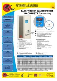
BOILER START-UP7Elements23 4 1 5 6 7 9 151 –LCD screen2 – HUW signal icon3 – HUW pump active icon4 – HUW program active icon5 – CH signal icon6 – CH pump active icon7 – CH program active icon8 – current HUW temperature9 – current CH temperature10 – time11 – data12 – CH and HUW temperature setting icon13 – floor heating icon14 – room temperature icon (optional)15 – weekday16 – relays status17 – function buttons18 –ON/OFF + back button19 – green diode – boiler turned on20 – red diode – boiler turned off21 – CHOOSE button81011c11:53:3312 05 2011 THU12 ESCONc1234561618OFF14TECHNICAL DATA13 20 19 17 21PowerManual powerdistributionModulation of Power Safety fuses (A) Power cord Heated area Alternativepower supply (mm²) (m²) heating (m²)4 kW100% - 67% - 33%by 1/31 phase1 x 203 x 2,5~ 50~ 704 kW100% - 67% - 33%by 1/33 phases3 x 65 x 1,5~ 50~ 706 kW100% - 67% - 33%by 1/31 phase1 x 323 x 4~ 70~ 1006 kW100% - 67% - 33%by 1/33 phases3 x 105 x 2,5~ 70~ 1009 kW100% - 67% - 33%by 1/61 phase1 x 403 x 10~ 110~ 1509 kW100% - 67% - 33%by 1/63 phases3 x 165 x 2,5~ 110~ 15012 kW100% - 67% - 33%by 1/63 phase3 x 205 x 4~ 150~ 21015 kW100% - 67% - 33%by 1/63 phases3 x 255 x 4~ 180~ 25018 kW100% - 67% - 33%by 1/63 phase3 x 325 x 6~ 220~ 31021 kW100% - 67% - 33%by 1/63 phases3 x 405 x 6~ 260~ 36024 kW100% - 67% - 33%by 1/63 phase3 x 405 x 10~ 300~ 400AsB II boiler Manual power Power Safety Power cord Heated area(kW) distribution (V) fuses (A) (mm²) (m²)AsB II boiler Power Safety Power cord(V) fuses (A) (mm²)EKW 27 9 ÷ 18 ÷ 27 400 3 x 50 5 x 16 220 - 380EKW 30 10 ÷20 ÷30 400 3 x 50 5 x 16 240 – 400EKW 33 11 ÷22 ÷33 400 3 x 50 5 x 16 260 – 450EKW 36 12 ÷ 24 ÷36 400 3 x 63 5 x 16 280 – 480EKW 39 13 ÷ 26 ÷39 400 3 x 63 5 x 16 290 – 500EKW 42 14 ÷ 28 ÷42 400 3 x 80 5 x 25 300 – 520EKW 45 15 ÷ 30 ÷45 400 3 x 80 5 x 25 320 – 570EKW 48 16 ÷ 32 ÷48 400 3 x 80 5 x 25 340 – 600EKW 54EKW 60EKW 66EKW 72EKW 96EKW 120EKW 1444004004004004004004003x100A3x100 A3x125 A3x125 A3x160 A3x200 A3x240 A5x355x505x505x505x705x955x120* Exact section should be matched by qualified electrician** Exact heated area depends on multiple factors
8SETTINGSSETTINGSATTENTION!!!!Boiler connected to the installation according to point II ELECTRICALASSEMBLY. CH (HUW) pump should be turned on for III speed. Valves onradiators should be completely open while start-up.3JEZYKPOLSKIENGLISHOKLANGUAGE1. Red diode on – no. 20, boiler stand-by – boiler turned on.2. For 5 s. Press button: Green diode no. 19 turns on.JEZYKPOLSKIENGLISHOKLANGUAGE3. Choose language POLSKI / ANGIELSKI (ENGLISH).– choose ENGLISH– back to POLISH– OK. Confirm language selection.4Venting4. On LCD – sign „venting + progress bar”. One cannot skip this part. CH(optionally HUW) pump turns on – there is no possibility to disconnectheaters. Those 5 minutes should be sufficient to vent whole systemincluding boiler and pump. In case however another venting is essentialplease repeat previous step.5c11:53:3312 05 2011 THUc1234565. On LCD – information according to description on page 7.1I – INITIAL SETTINGS:1 CH and HUW (concerns AsD-W and AsDC-W boilers only) temp. setting– press 1 time, enter function:HUW50CH50– go to CH setting– get back to HUW settingHUW.CHCONTROL PANEL5050CH and HUW temperatures are set in the same way.ESCONOFF
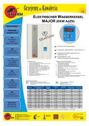
SETTING9- press another time, below sign appears:HUWCH- decrease CH or HUW temp.- increase CH or HUW temp.- „BACK” (given parameters are set)Multiple press enables getting back to main menu50°C50°CHUWDEFAULT: 50CH2 „Weather curve” settingDEFAULT: 50- press 1 time, enter the „weather curve” setting- choose curve from 0 to 10Weather curves operate for outside temperatures lower than 15°C. Tomake them work properly one should set CH temperature, e.g. 30°C andchoose curve number (1 – 10). Zero – no weather correction.Meaning of values:Boiler keeps fixed CH temperature – the one we have previously chosen.This temperature is then increased by weather correction value, i.e.boiler’s temperature = set temperature + weather correction; wherecorrection factor depends on our choice.For each grade below 15°C, weather correction equals:2c11:53:3312 05 2011 THUc k:050 (+0 ) cc123456123456for 10,1°Cfor 20,2°Cfor 3for 4for 5for 60,3°C0,4°C0,5°C0,6°CBoiler temp8070K=10for 7for 80,7°C0,8°C6050K=5for 9for 100,9°C1,0°C4030K-=1ExamplesWeather curve set at 5, boiler CH temperature: 30°C. For outside temperaturehigher than 15°C boiler will keep 30°C. For external temperature equal 5°C,correction will estimate 10 x 0,5 = 5°C, thus boiler will maintain 35°C. For externaltemperature equal - 5°C numbers will be: 20 x 0,5 = 10°C, boiler temp.: 40°C.External temp.20 10 0 -10 -20 -30Curves 1, 5, 10 for CH temp. 30°C
10SETTINGS3. Room temperature setting on boiler (optional)- press 1 time, enter the function: Room temperaturesetting on boiler- decrease CH or HUW temp. (from 5° to 29°C)- increase CH or HUW temp. (from 6° to 30°C)ad. 3c11:53:3312 05 2011 THUc123456- „BACK” (given temperatures are set)Multiple press enables getting back to main menuck:19 c25 c123456I – SETTINGS FROM MENU:A. SETTINGS:1. POWER . . . . . . . . . . . . . . . . . . . 100 / 67 / 33%2. SECTIONS . . . . . . . . . . . . . . . . . . . . CH and HUW3. DATE & TIME . . . . . . . . . . . . . . . . current4. PID-P . . . . . . . . . . . . . . . . . . . 1 – 2 – 3 – 4 – 55. CH HISTERESE. . . . . . . . . . . . 1 – 2 – 3 – 4 – 5 – 6 °C6. HUW HISTERESE. . . . . . . . . . . 1 – 2 – 3 – 4- 5 – 6 °C7. DEF. SETTINGS8. CONTROLS ROOM (OPTIONAL) . . . . . . . 9 programs9. CONTROLs HUW (OPTIONAL) . . . . . . . . 9 programsB. ENERGY CONSUMPTIONC. VENTING (CH and HUW)Ad. A1. „SETTINGS – POWER” EKW boiler- press 1 time, SETTINGS sign appears- press 2 times, POWER sign appears- press another time, below sign appearsPOWER100%- decrease boiler power to 67% or 33%- increase boiler power to 67% or 100%- „BACK” (given parameters are set)Multiple press enables getting back to main menuad. A1SETTINGSENERGY CONSUM.VENTINGPOWERSECTIONSDATE & TIMEPID-PCH HISTERESEPOWERDEFAULT: 100POWERDEFAULT: 1006612
SETTING11ad. A2Ad. A2. „SETTINGS – SECTIONS ” active CH and HUW.- press 1 time, SETTING sign appears- press 2 times, SECTIONS sign appearsSETTINGSENERGY CONSUM.VENTING- (to enter SECTION area press one time button:Another press shows below screen:)HUWCHONONHUWCHONON- press 1 time, enter CH functionIf we would like to turn off HUW, do not press this function- press another time, below screen appearsHUWCH(when we turn off CH function)(when we turn off HUW function.)ONONHUWCHONON- OFF – section inactive- ON – section active- „BACK” (given parameters are set)Multiple press enables getting back to main menuCHCHad. A3Ad. A3. „SETTINGS – DATE & TIME”- press 1 time, SETTING sign appears- press 2 times, DATE & TIME sign appears(to enter press twice button on the right )SETTINGSENERGY CONSUM.VENTING- press another time, below screen appearsDate, time and weekday- change parameter- change parameter’s value- „BACK” (given parameters are set)POWERSECTIONSDATE & TIMEPID-PCH HISTERESE6612Multiple press enables getting back to main menuFRI
12SETTINGSAd. A4. „SETTINGS – PID-P” – proportional integral derivative controller- press 1 time, SETTINGS sign appears- press 2 times, PID-P sign appears(to enter press three times button on the right- press another time, PID-P function is visible- change parameter- change parameter’s valueATTENTION:In case boiler needs long time to achieve set temperature - set 4 or 5In case boiler reaches set temperature to quickly – set 1 or 2)ad. A4SETTINGSENERGY CONSUM.VENTINGPOWERSECTIONSDATE & TIMEPID-PCH HISTERESE6612- „BACK” (given parameters are set)Multiple press enables getting back to main menuPID-PDEFAULT: 2Ad. A5. „SETTINGS – CH HISTERESE”- press 1 time, SETTING sign appears- press 2 times, CH HISTERESE sign appears(to enter press four times button on the right)ad. A5SETTINGSENERGY CONSUM.VENTING- press another time, below screen is visibleCH HISTERESE- decrease histerese 1 – 2 – 3 – 4 - 5- increase histerese 2 – 3 – 4 – 5 – 6- „BACK” (given parameters are set)Multiple press enables getting back to main menu6 POWERSECTIONSDATE & TIMEPID-PCH HISTERESECH HISTERESE6612DEFAULT: 4
SETTINGS13ad. A6Ad. A6. „SETTINGS – HUW HISTERESE”- press 1 time, SETTINGS sign appears- press 2 times, HUW HISTERESE sign appears(to enter press five times button on the right)SETTINGSENERGY CONSUM.VENTING- press another time, below screen is visibleHUW HISTERESE6 SECTIONS- decrease histerese 1 – 2 – 3 – 4 - 5DATE & TIMEPID-P- increase histerese 1 - 2 – 3 – 4 – 5 – 6 (recommended 6) CH HISTERESE- „BACK” (given parameters are set)HUW HISTERESEMultiple press enables getting back to main menu.124HUW HISTERESEDEFAULT: 4Ad. A7. „SETTINGS – DEF. SETTINGS”- press 1 time, SETTINGS sign appears- press 2 time, DEF. SETTINGS sign appears(to enter press six times button on the right- press another time, below screen is visible)ad. A5SETTINGSENERGY CONSUM.VENTINGDEF. SETTINGS- NO - resigning from default settings- YES - approving default settings- OK - activating default settings- HUW temperature . . . . . . . . . 50°C- CH temperature. . . . . . . . . . . 50°C- Bioler power . . . . . . . . . .. . . . . 100%- HUW sections. . . . . . . . . . . . . . ON- CH sections. . . . . . . . . . . . . . . . ON- PID-5 . . . . . . . . . . . . . . . . . . . . . . 3- CH histerese. . . . . .. . . . . . . . . . 6- HUW histerese . . . . . . . . . . . . . 7- „BACK” (given parameters are set)Multiple press enables getting back to main menuDATE & TIMEPID-PCH HISTERESEHUW HISTERESEDEF. SETTINGSDEF. SETTINGSNODEF. SETTINGSNOYESYES124OKOK
14 SETTINGSWEEKLY PROGRAMMING ON BOILER + HUW TIME PROGRAMMING (OPTIONAL)- are not a standard boiler equipmentWeekly programming on boiler, as well as HUW time programming enables setting and maintaininggiven temperature at any defined time periods with minute accuracy. Limpid menu and illuminateddisplay makes the whole setting process easy. All previously selected parameters are memorized innon-volatile boiler memory. Electronic processor can steer up to 9 programs, each enables settingrequested temperature in any given time period.1. In case of two temperature ranges overlapping, the one with higher, more comfort temperature ischosen.2. In case of a program overlapping with INITIAL SETTINGS (pt. I ad.1), boiler will heat according tochosen program variant.VariantWEEKDAY PROGRAMINGIMOTUWETHFRSASUAll days activeIIMOWEFRSU4 days activeIIIMOTHSU3 days activeIVMOTUWETHFRSASU1 day active (free choice)VMOTUWETHFRWorkdays activeVISASUWeekend activeVII MO TU WE TH FRSA6 days active1.2.3.4.5.6.7.MO TU WE TH FR SA SU – weekdaysSTART – turn the program onSTOP – turn the program offTEMP – settings from 20°C to 70°CAKTYWNY – YES/NOPROGRAM NO. – 1 to 9FUNCTION BUTTONS 12345TU WESTART:STOP:TEMP:ACTIVE:TH FR SA SU08:0316:00 NR.25 cYES6ESCONOFF7
SETTINGSAd. A8. „SETTINGS –PROGRAMS ROOM” (OPTIONAL)- press 1 time, SETTINGS sign appears- press 2 time, PROGRAMS ROOM sign appears(to enter press seven times button on the right)- press another time, settings menu is visiblead. A8SETTINGSENERGY CONSUM.VENTING15- change parameter- change parameter’s value- „BACK” (given parameters are set)Multiple press enables getting back to main menuPID-PCH HISTERESEHUW HISTERESEDEF. SETTINGSPROGRAMS ROOMTU WESTART:STOP:TEMP:ACTIVE:124TH FR SA SU08:0316:00 NR25 CYESTU WESTART:STOP:TEMP:ACTIVE:TH FR SA SU08:0316:00 NR25 CYESad. A8Ad. A9. „SETTINGS –PROGRAMS HUW” (OPTIONAL)- press 1 time, SETTINGS sign appears- press 2 time, PROGRAMS HUW sign appears(to enter press seven times button on the right )- press another time, settings menu is visible- change parameter- change parameter’s value- „BACK” (given parameters are set)Multiple press enables getting back to main menuSETTINGSENERGY CONSUM.VENTINGCH HISTERESEHUW HISTERESEDEF. SETTINGSPROGRAMS ROOMPROGRAMS HUWTU WESTART:STOP:TEMP:ACTIVE:24TH FR SA SU08:0316:00 NR25 CYEStakTU WESTART:STOP:TEMP:ACTIVE:TH FR SA SU08:0316:00 NR25 CYEStak
16ACTIVE / NONACTIVE PROGRAMEach program can be temporarily deactivated.One should then turn in PROGRAMS ROOM or PROGRAMS HUW:ACTIVE: NOIn case we want to turn the program on:ACTIVE: YESSETTINGSTU WE TH FR SA SUSTART:STOP:TEMP:ACTIVE:08:031 6 :0025 CNONRTU WE TH FR SA SUSTART:STOP:TEMP:ACTIVE:08:031 6 :0025 CYESNRAd. A9. „ENERGY CONSUMPTION”- press 1 time, SETTINGS sign appears- press 1 time, go to ENERGY CONSUM.- press 1 time, counters appearad. A9SETTINGSENERGY CONSUM.VENTING- RST – reset erasable counterRESETABLE COUNTER: consumed energy in kWh (sincemeasurement start for max 24h). After 24h counter stopsautamatically.RES. COUNTER:LAST 24h:LAST 24H: counter shows actual energy consumption for thelast 24h – update every 20 min.RST- „BACK” (given parameters are set)Multiple press enables getting back to main menuAd. A10. „VENTING”1. Function enables additional system venting without turning boiler off.Proper system venting guarantees its proper operation, as well as prevents wholeinstallation from too quick wear.ad. A10SETTINGSENERGY USAGEVENTING2. Additional possibility to check whether CH and HUW pumps operate properly.- press 1 time, SETTINGS appear- press 2 times, go to VENTING function
SETTINGS17- press 1 time, below screen appears:HUW(turn on HUW bleeding)ONHUWCHOFFOFFCHON- press 1 time – go to HUW function: OFF- press 1 time – turn on HUW bleeding: ONSame method applies to CH installationHUW- After proper venting process, one should turn function off:HUWCH- „BACK” (given parameters are set)Multiple press enables getting back to main menuOFFOFFHUWREFERENCE DIAGRAMSExemplary application of AsZN-W boiler(Max. Operation temperature 40°C)AsZN-W boiler in floor heating instalationAsZN-W as an independent heat sourceAsDC-W boilerWith build-in HUW tank – exemplary diagramAsZN-W boiler with HUW tank- heating large quantities of water in short timecirculationHUWoutflowCold waterinflow.CHCHsafetyvalveballvalvemanometercirculationpumpmembranevessel
DECLARATION OF CONFORMITY18DECLARATION OF CONFORMITY EC No. 1/2011ELTERM M.M. KASZUBA SP.J. 86-200 CHEŁMNO UL. PRZEMYSŁOWA 5We herewith declare, under our sole responsibility, that the following products: Tankless waterheater for central heating systems (electric central heating water boiler)TYPE:• EKW4As, EKW6As, EKW9As (~230V,50Hz, max power 4kW, 6kW, 9kW),• EKW4As, EKW6As, EKW9As, EKW12As, EKW15As, EKW18As, EKW21As, EKW24As, EKW27As, EKW30As, EKW33As,EKW36As, EKW39As, EKW42As, EKW45As, EKW48As (3N~400V,50Hz, max power 4kW, 6kW, 9kW, 12kW, 15kW,18kW, 21kW, 24kW, 27kW, 30kW, 33kW, 36kW, 39kW, 42kW, 45kW, 48kW)• EKW-AsBII (3N~400V,50Hz, combined max power 54- 960kW, boilers’ cascade, each up to 48kW)Models: AsPC, AsP, AsBN, AsZN, AsD, AsBI, AsZN-W, AsD-W, AsDC-W, AsBIImanufactured at the <strong>Elterm</strong> production plant, are in conformity with the applicable provisions of the following EC Directives:Directive no.73/23/EWG as amended89/336/EWG as amendedNr 2002/95/WE as amendedNr 2002/96/WE as amendedTitle::Low Voltage Directive (LVD)Electromagnetic Compatibility Directive (EMC)Directive on the restriction of the use of certain hazardous substances in electrical andelectronic equipment (RoHS)Directive on waste electrical and electronic equipment (WEEE); GIOŚ reg. no.: E0001767and that the standards hereinafter referred to have been duly applied and observed. The last two digits of the year of the CEmarking application: 08. The harmonized standards applicable to the product to which this declaration of conformity pertains:Number:PN-EN 60335-1Issue::94+A11:95+A1:96+A12:96+A13:98+A14:98+A2:2000+A15:2000+A16:2001:2004/A1:2005/A12:2006(U)Title:Safety of household and similar electrical appliancesPN-EN 60335-2-35 :1998+A1:2000:2005/A1:2007(U)PN-EN 55014-1 :2002+A1PN-EN 55014-2 :1999+A1:2004PN-EN 61000-3-2 :2004PN-EN 61000-3-11 :2000PN-EN 50366 :2004+A1:2006(U)Particular requirements for tankless water heatersInterference emission for household appliancesInterference immunityHarmonic current emissionsLimitations of voltage fluctuationsElectromagnetic fields - methods for evaluationAnd measurementOther documents or information required by the EC Directives:Report no.:B-47/03CLBT/ZR/67/2003456/BS/EMC/04BE/39/2006BEM-66/07B-71/07Date:24.06.200309.07.200327.04.200427.01.200617.10.200717.10.2007Laboratory:KEWA - ECO, BydgoszczGP - CLBT, WarszawaPREDOM - OBR, WarszawaLaboratorium Elektrotechniczne PCBC S.A.Laboratorium Badawcze Maszyn i Urządzeń J.N.B. EUROVITA Sp. z o.o.Laboratorium Badawcze Maszyn i Urządzeń J.N.B. EUROVITA Sp. z o.o.Chełmno, 2011.05.07Maciej Kaszuba
WE ALSO RECOMMEND:HYDRAULIC BALANCERS SHE, SHE-SP, SHE-OCfrom 25 to 420 kWLEATHERETTECOATPUR FOAM0,025W/mKHYDRAULIC BALANCERSSHE-ELTERMHYDRAULIC BALANCERSSHE-SP ELTERMWITH AIR SEPARATORHYDRAULIC BALANCERSSHE-OC ELTERM INSULATEDPUMP MODULES WITH MIX SYSTEMBoiler's pump module with mix systemFloor heating's pump module with mix systemADVANTAGES:- Boiler's return protection (against deweffect)- Required along with new solid fuel CHboilers installation (guarantee terms)- Pump work regulation according totemperature differences (supply vs.return) - (turns pump off when lowsupply temp. occurs)- In case there is no separate safetypipe in CH, boiler will not be cutoff from open system vessel (as ithappens in case of 3- and 4-wayvalves)- Floor area - up to 120m²,- Possibility to link up two separate funnels- Regulation from 2° to 50°CDetails on www.elterm.pl
Reccomended room temperature controllers: ThermLine RTRoom temperature controllersThermLine RTPump temperature controllersThermLine PTThermLine RT–R (air temp.)ThermLine RT–F (floor temp.)ThermLine RT–RF (air-floor temp.)ThermLine RT–RW (wireless air temp.)ThermLine PT-P2ThermLine PT-P3ThermLine PT-P4controlls CH or HUW pumpcontrolls HUW pumpcontrolls CH and HUW pumpAdvantages of RT controller:• Programming with accuracy of 1 min.• 9 independent programs• Actual temperature setting• Accurate hysteresis - from +/- 0,1°C to +/- 1°C• Removable steering panel (safe installation)• Build-in installator mode• 16A relay• Non-volatile memoryAdvantages of PT controller:• LED display• Intelligent Anti Stop system• Anti-freeze• Simple handlingElectric towel rails and bathroom heaters ECO 70 ÷ 110 Wand ECOTERM 320 ÷ 800 W with stepless power regulationFull offer on www.elterm.plrok założenia1992ELTERM M.M. Kaszuba SP.J.:86-200 Chełmno, ul. Przemysłowa 5, POLSKA,tel. (0048) 56/686 93 05, 692 06 06, biuro@elterm.pl • www.elterm.pl