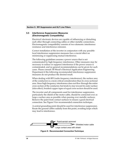
Section 5: RFI Suppression and XLF Line Filters5.5 Interference Suppression Measures(Electromagnetic Compatibility)Electrical/electronic devices are capable of inßuencing or disturbingeach other through connecting cables or other metallic connections.Electromagnetic compatibility consists of two elements: interferenceresistance and interference emission.Correct installation of the inverter in conjunction with any possiblelocal interference suppression measures has a crucial effect onminimizing or suppressing mutual interference.The following guidelines assume a power source that is notcontaminated by high frequency interference. Other measures may benecessary to reduce or suppress interference if the power source iscontaminated, and no general recommendations can be given for suchcases. Please consult TB WoodÕs Electrical Application EngineeringDepartment if the following recommended interference suppressionmeasures do not produce the desired result.When dealing with RFI (radio frequency interference), the surface areaof the conductors is a more critical consideration than its cross sectionalarea. Since high frequency interference does not ßow through the entirecross section of the conductor, but tends to stay toward its outer surface(skin effect), braided copper tapes of equal cross section should be used.The inverter and all components used for interference suppression,particularly the shield of the motor cable, should be connected over aslarge a surface area as possible when passing over metallic surfaces.Remove the paint from contact surfaces to ensure a good electricalconnection. See Figure 9 for recommended connection technique.A central grounding point should be used for interference suppression.Route the ground cables radially from this point, avoiding loops whichmay lead to interference.Paint/varnish removedShielded motor cableLarge contact area with shieldFigure 9: Recommended Connection Technique38© 1998 TB Wood’s All Rights Reserved
Section 5: RFI Suppression and XLF Line FiltersTake care not to damage the shield cross section when connecting it tothe continuing lines. This raises the RF resistance of the shield andradiates rather than discharges the RF energy traveling on the shield.Shields, particularly those on control cables, must not be routedthrough pin contacts (plug connectors). When shielded cables mustpass through a plug connection, use the metallic hand guard of the plugfor the continuation of the shield. It is strongly recommended that theshield be uninterrupted whenever possible.Use a shielded motor cable which is grounded over a large surface areaat both ends. The shield on this cable should be uninterrupted. If ashielded motor cable cannot be used, the unshielded motor line shouldbe laid in a metal conduit or duct which is uninterrupted and groundedat both ends.When selecting shielded cable for use as motor leads, it is important toselect a cable which is designed for operation at the frequencies andpower levels involved. Improper selection of motor cable can causehigh potential to exist on the shield. This could cause damage to theinverter and other equipment, and could pose a safety hazard. Thefollowing cables are acceptable for this purpose:¥ OLFlex 1 <strong>Series</strong> 150CY, 110CY, 110CS, 100CY, 100CS, and 540CP¥ Siemens 2 Cordaßex SMIf the installation requires the use of an output reactor, the reactor, likethe line Þlter, should be placed a close as possible to the inverter.Some of these cables are VDE approved only; others carry VDE, UL,CSA, and combinations of these ratings. Be sure to conÞrm that thecable you are using meets the certiÞcation of the agency required.Control wires longer than 3 feet must be run in shielded cable, and theshield must be terminated at common (CM) on the inverter. Note thatconnection to CM, the circuit common, rather than earth ground, isallowed because X2C inverters have isolated control inputs. If thesignal run exceeds 30 feet, a 0-20 mA or 4-20 mA signal should be used,as it will have better noise immunity than a low level voltage.1. OLFlex Wire & Cable, 30 Plymouth Street, FairÞeld, NJ 07004 (800) 774-3539.2. Siemens Energy and Automation, Inc., Power Cables, 3333 State Bridge Road, Atlanta, GA 30202(800) 777-3539.© 1998 TB Wood’s All Rights Reserved 39