


You also want an ePaper? Increase the reach of your titles
YUMPU automatically turns print PDFs into web optimized ePapers that Google loves.
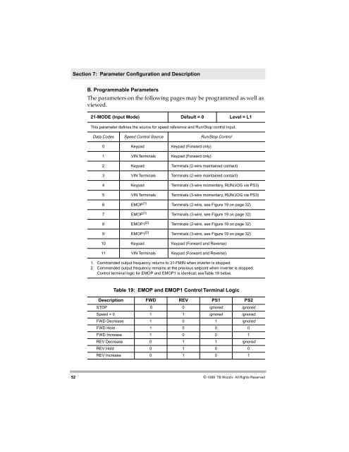
Section 7: Parameter Configuration and DescriptionB. Programmable ParametersThe parameters on the following pages may be programmed as well asviewed.21-MODE (Input Mode) Default = 0 Level = L1This parameter defines the source for speed reference and Run/Stop control input.Data Codes Speed Control Source Run/Stop Control0 Keypad Keypad (Forward only)1 VIN Terminals Keypad (Forward only)2 Keypad Terminals (2-wire maintained contact)3 VIN Terminals Terminals (2-wire maintained contact)4 Keypad Terminals (3-wire momentary, RUN/JOG via PS3)5 VIN Terminals Terminals (3-wire momentary, RUN/JOG via PS3)6 EMOP [1] Terminals (2-wire, see Figure 19 on page 32)7 EMOP [1] Terminals (3-wire, see Figure 19 on page 32)8 EMOP1 [2] Terminals (2-wire, see Figure 19 on page 32)9 EMOP1 [2] Terminals (3-wire, see Figure 19 on page 32)10 Keypad Keypad (Forward and Reverse)11 VIN Terminals Keypad (Forward and Reverse)1. Commanded output frequency returns to 31-FMIN when inverter is stopped.2. Commanded output frequency remains at the previous setpoint when inverter is stopped.Control terminal logic for EMOP and EMOP1 is identical; seeTable 19 below.Table 19: EMOP and EMOP1 Control Terminal LogicDescription FWD REV PS1 PS2STOP 0 0 ignored ignoredSpeed = 0 1 1 ignored ignoredFWD Decrease 1 0 1 ignoredFWD Hold 1 0 0 0FWD Increase 1 0 0 1REV Decrease 0 1 1 ignoredREV Hold 0 1 0 0REV Increase 0 1 0 152© 1998 TB Wood’s All Rights Reserved