PPMS Test for a Plugged Impedance - Quantum Design, Inc.
PPMS Test for a Plugged Impedance - Quantum Design, Inc.
PPMS Test for a Plugged Impedance - Quantum Design, Inc.
- No tags were found...

Create successful ePaper yourself
Turn your PDF publications into a flip-book with our unique Google optimized e-Paper software.
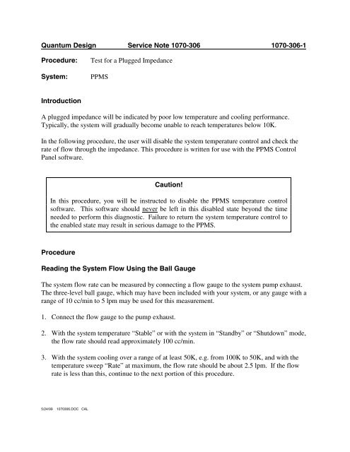
<strong>Quantum</strong> <strong>Design</strong> Service Note 1070-306 1070-306-1Procedure:System:<strong>Test</strong> <strong>for</strong> a <strong>Plugged</strong> <strong>Impedance</strong><strong>PPMS</strong>IntroductionA plugged impedance will be indicated by poor low temperature and cooling per<strong>for</strong>mance.Typically, the system will gradually become unable to reach temperatures below 10K.In the following procedure, the user will disable the system temperature control and check therate of flow through the impedance. This procedure is written <strong>for</strong> use with the <strong>PPMS</strong> ControlPanel software.Caution!In this procedure, you will be instructed to disable the <strong>PPMS</strong> temperature controlsoftware. This software should never be left in this disabled state beyond the timeneeded to per<strong>for</strong>m this diagnostic. Failure to return the system temperature control tothe enabled state may result in serious damage to the <strong>PPMS</strong>.ProcedureReading the System Flow Using the Ball GaugeThe system flow rate can be measured by connecting a flow gauge to the system pump exhaust.The three-level ball gauge, which may have been included with your system, or any gauge with arange of 10 cc/min to 5 lpm may be used <strong>for</strong> this measurement.1. Connect the flow gauge to the pump exhaust.2. With the system temperature “Stable” or with the system in “Standby” or “Shutdown” mode,the flow rate should read approximately 100 cc/min.3. With the system cooling over a range of at least 50K, e.g. from 100K to 50K, and with thetemperature sweep “Rate” at maximum, the flow rate should be about 2.5 lpm. If the flowrate is less than this, continue to the next portion of this procedure.5/24/99 1070306.DOC CAL
<strong>Quantum</strong> <strong>Design</strong> Service Note 1070-306 1070-306-2Reading the System Flow Using the Gas Monitor Utility1. Set the system temperature to 100K and allow the temperature to stabilize.2. Open the Gas Monitor (GasMon) utility. This software is included with the original softwareand is opened separately from the <strong>PPMS</strong> Control Panel. It is opened from Windows byselecting the file C:\$DIAG\<strong>PPMS</strong>\GASMON.EXE.3. Open the Acq menu of the Gas Monitor panel and select Set Rate.4. Set the acquisition rate to Every Second.5. Now open the Config menu and select Temp Package. If the Temp Package item is grayedout, use the following instructions to enable this item:a) Open the File menu.b) Select Advanced.c) When Advanced is selected, you may be asked to enter a password (earlierversions of software only). This password is quandsnNote: Earlier versions of <strong>PPMS</strong> software disabled the password setting effective January 1,1997. If the quandsn password does not work, set the computer system date to a dateprior to January 1, 1997.d) At this time, the Temp Package menu item will be enabled. Select TempPackage and continue.8. Select Asleep to place the temperature control system in manual mode. When this isdone, the message “Temperature is Asleep!” will appear in red on the Gas Monitor panel.9. After the temperature control system has been “asleep" <strong>for</strong> a few seconds, the impedanceshould read “OFF, Cool”. If it does not read “OFF, Cool”, verify that the temperaturecontrol is asleep. If the temperature control is asleep and the impedance status does notread “OFF,Cool,” re-activate the temperature control system by selecting Temp Packageand Awake, close the GasMon software, and contact your <strong>Quantum</strong> <strong>Design</strong> ServiceRepresentative <strong>for</strong> additional assistance.10. Open the cooling valve by double-clicking on the valve icon (a circle with two parallellines inside it) at the bottom of the “Probe” panel. The cooling valve icon is the lowestvalve shown in the display. It is located to the bottom right of the “Probe” icon. Whenyou click on this icon, the valve should open to the 90° position (the valve icon will bealigned with the surrounding lines). Note: The valve may already be in the 90° position.If it is, continue to the next step.5/24/99 1070306.DOC CAL
<strong>Quantum</strong> <strong>Design</strong> Service Note 1070-306 1070-306-311. With the valve fully open, read the flow rate displayed at the top of the screen in the“Model 6000" section of the panel. The flow rate should be about 2.5 lpm. If it is higherthan 2.8 lpm, a leak may be indicated. If it is lower than 2.0, the impedance is plugged.Note: If the flow rate reported in Step 10 does not agree with the flow rate from theball gauge reading, a problem may exist with the valve calibration in the Model 6000. Ifthis is the case, please contact your <strong>Quantum</strong> <strong>Design</strong> Service Representative.12. Return to the Config, Temp Package menu and select “Awake” to re-activate thetemperature control system. The “Temperature Control Asleep” message should clearand the temperature status on the Model 6000 front panel should read “chasing” or“Stable.”13. Close the GasMon program.Clearing a <strong>Plugged</strong> <strong>Impedance</strong>If the impedance is plugged (the flow rate is lower than 2.0 lpm in step 9 above) it is necessary tofully warm the system - the dewar must have no helium in it, the probe must be allowed to sit atroom temperature <strong>for</strong> at least 48 hours.Following this drying period, the system flow rate should be checked be<strong>for</strong>e re-cooling thesystem. This is done by flowing helium gas into the dewar at approximately 100 cc/min, toachieve a pressure of about 1 psi inside the dewar. Under these conditions, set the systemtemperature to 5K (it will not be able reach this temperature) and monitor the exhaust flow fromthe system pump using the ball gauge (the Model 6000 flow gauge is not calibrated to beaccurate at this low rate). The flow rate should be about 20 cc/min. If the flow rate is not at least20 cc/min, the impedance may still be plugged. Allow the probe to stand an additional 24 hoursand try again.If the flow rate is still limited after at least 72 hours, contact your <strong>Quantum</strong> <strong>Design</strong> ServiceCenter <strong>for</strong> assistance.5/24/99 1070306.DOC CAL