Ch 11 - Generator Protection
Ch 11 - Generator Protection
Ch 11 - Generator Protection

You also want an ePaper? Increase the reach of your titles
YUMPU automatically turns print PDFs into web optimized ePapers that Google loves.
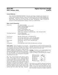
<strong>Generator</strong> <strong>Protection</strong>GENERATOR CONTROL AND PROTECTION
<strong>Generator</strong> <strong>Protection</strong>• Introduction• Device Numbers• Symmetrical Components• Fault Current Behavior• <strong>Generator</strong> Grounding• Stator Phase Fault (87G)• Field Ground Fault (64F)• Stator Ground Fault (87N, 51N, 59N, 27-3N)GENERATOR CONTROL AND PROTECTION
<strong>Generator</strong> <strong>Protection</strong>• Loss of Field (40Q, 40Z)• Over/Under Frequency (81O/81U)• Overexcitation and Overvoltage (24, 59)• Out of Step (78)• Negative Sequence (Current Unbalance) (46)• Inadvertent Energization (27, 50, 60, 81, 62, 86)• Loss of Voltage Transformer (60)• System Backup (51V, 21)• ConclusionGENERATOR CONTROL AND PROTECTION
<strong>Generator</strong> <strong>Protection</strong>49G632564F51N87G60REG51244787T622781U5159 81O32-132-240 51V50IE4659N27-3N51-GNGENERATOR CONTROL AND PROTECTION
Steam <strong>Generator</strong> Stator WindingsGENERATOR CONTROL AND PROTECTION
Hydraulic <strong>Generator</strong> Stator CoreGENERATOR CONTROL AND PROTECTION
<strong>Generator</strong> <strong>Protection</strong>GENERATOR CONTROL AND PROTECTION
Split Phase Relaying CTGENERATOR CONTROL AND PROTECTION
Cylindrical Rotor in Need of RepairGENERATOR CONTROL AND PROTECTION
<strong>Generator</strong> <strong>Protection</strong>GENERATOR CONTROL AND PROTECTION
<strong>Generator</strong> <strong>Protection</strong>GENERATOR CONTROL AND PROTECTION
Symmetrical Components• Positive Sequence– A set of three phasors that have the same magnitude, are equallydisplaced from each other by 120º, and have the same phasesequence as the system under study (ex ABC)• Negative Sequence– A set of three phasors that have the same magnitude, are equallydisplaced from each other by 120º, and have the opposite phasesequence as the system under study (ex ACB)• Zero Sequence– A set of three phasors of equal magnitude that are all in phase orhave zero displacement from each otherGENERATOR CONTROL AND PROTECTION
Symmetrical ComponentsGENERATOR CONTROL AND PROTECTION
Symmetrical ComponentsGENERATOR CONTROL AND PROTECTION
Symmetrical ComponentsGENERATOR CONTROL AND PROTECTION
Symmetrical ComponentsGENERATOR CONTROL AND PROTECTION
Symmetrical ComponentsGENERATOR CONTROL AND PROTECTION
Example ProblemSymmetrical Components• One conductor of a three phase line isopen. The current flowing to the deltaconnected load thru line a is 10A. Withthe current in line a as reference andassuming that line c is open, find thesymmetrical components of the linecurrents.GENERATOR CONTROL AND PROTECTION
Symmetrical ComponentsExample Problem• I a = 10/0° A, I b = 10/180° A, I c = 0 A• I a0 = (1/3)(I a + I b + I c )• I a0 = (1/3)(10/0° + 10/180° + 0) = 0• I a1 = (1/3)(I a + αI b + α 2 I c )• I a1 = (1/3)(10/0° + 10/180+120° + 0)• I a1 = 5.78 /-30°• I a2 = (1/3)(I a + α 2 I b + αI c )• I a2 = (1/3)(10/0° + 10/180+240° + 0)• I a2 = 5.78 /30°GENERATOR CONTROL AND PROTECTION
Symmetrical ComponentsExample Problem• I b0 = 0• I b1 = 5.78 /-150°• I b2 = 5.78 /150°• I c0 = 0• I c1 = 5.78 /90°• I c2 = 5.78 /-90°GENERATOR CONTROL AND PROTECTION
Symmetrical ComponentsExample Problem• I a0 = 0, I b0 = 0, I c0 = 0• I a1 = 5.78 /-30° , I b1 = 5.78 /-150° , I c1 = 5.78 /90°• I a2 = 5.78 /30° , I b2 = 5.78 /150° , I c2 = 5.78 /-90°GENERATOR CONTROL AND PROTECTION
Example ProblemSymmetrical Components• Note: the components I c1 and I c2 havedefinite values although line c is open andcan carry no net current. As expected, thesum of these currents is zero.• The sum of the currents in line a is 10/0°• The sum of the currents in line b is 10/180°GENERATOR CONTROL AND PROTECTION
Symmetrical ComponentsSingle Phase Line to Ground FaultGENERATOR CONTROL AND PROTECTION
Symmetrical Components<strong>Generator</strong> Sequence NetworksGENERATOR CONTROL AND PROTECTION
Symmetrical ComponentsGENERATOR CONTROL AND PROTECTION
Symmetrical ComponentsGENERATOR CONTROL AND PROTECTION
Fault Current Behavior of aSynchronous <strong>Generator</strong>GENERATOR CONTROL AND PROTECTION
Fault Current Behavior of aSynchronous <strong>Generator</strong>GENERATOR CONTROL AND PROTECTION
Fault Current Behavior of aSynchronous <strong>Generator</strong>GENERATOR CONTROL AND PROTECTION
Fault Current Behavior of aSynchronous <strong>Generator</strong>Max DC OffsetNo DC OffsetGENERATOR CONTROL AND PROTECTION
Fault Current Behavior of aSynchronous <strong>Generator</strong>GENERATOR CONTROL AND PROTECTION
Fault Current Behavior of aSynchronous <strong>Generator</strong>GENERATOR CONTROL AND PROTECTION
<strong>Generator</strong> GroundingGENERATOR CONTROL AND PROTECTION
<strong>Generator</strong> Grounding•Low Impedance Grounding•Single phase to ground fault current between 200A and 150%•High Impedance Grounding•Single phase to ground fault current between 5 and 20AGENERATOR CONTROL AND PROTECTION
<strong>Generator</strong> Stator Phase Fault<strong>Protection</strong> (87G)GENERATOR CONTROL AND PROTECTION
<strong>Generator</strong> Stator Phase Fault<strong>Protection</strong> (87G)•87G used to protect for:•3 phase line to line•1 phase line to line•multi-phase line to ground•May not be able to detect a 1 phase to ground fault on highimpedance grounded generators•Restraint or Percentage Differential Trip <strong>Ch</strong>aracteristic•Used to improve sensitivity for detecting small levels offault current•Also maintains security against inadvertent tripping dueto thru faultsGENERATOR CONTROL AND PROTECTION
<strong>Generator</strong> Stator Phase Fault<strong>Protection</strong> (87G)GENERATOR CONTROL AND PROTECTION
<strong>Generator</strong> Stator Phase Fault<strong>Protection</strong> (87G)GENERATOR CONTROL AND PROTECTION
<strong>Generator</strong> Stator Phase Fault<strong>Protection</strong> (87G)•Split-phase protection scheme•Able to detect turn-turn faults•Windings for each phase split into equal groups•Individual winding currents are vector summed•Any difference in winding current results in a output from CT•Overcurrent relay (50/51) can be used to monitor differencecurrent•Setting must be above any normal unbalances that may existGENERATOR CONTROL AND PROTECTION
<strong>Generator</strong> Stator Phase Fault<strong>Protection</strong> (87G)GENERATOR CONTROL AND PROTECTION
<strong>Generator</strong> Field Ground Fault<strong>Protection</strong> (64F)GENERATOR CONTROL AND PROTECTION
<strong>Generator</strong> Stator Ground Fault<strong>Protection</strong> (87N, 51N, 59N & 27-3N)For Low Impedance Grounded <strong>Generator</strong>sGENERATOR CONTROL AND PROTECTION
<strong>Generator</strong> Stator Ground Fault<strong>Protection</strong> (87N, 51N, 59N & 27-3N)For Low Impedance Grounded <strong>Generator</strong>sGENERATOR CONTROL AND PROTECTION
<strong>Generator</strong> Stator Ground Fault<strong>Protection</strong> (87N, 51N, 59N & 27-3N)External <strong>Generator</strong> Phase-Ground FaultGENERATOR CONTROL AND PROTECTION
<strong>Generator</strong> Stator Ground Fault<strong>Protection</strong> (87N, 51N, 59N & 27-3N)External <strong>Generator</strong> Phase-Ground FaultGENERATOR CONTROL AND PROTECTION
<strong>Generator</strong> Stator Ground Fault<strong>Protection</strong> (87N, 51N, 59N & 27-3N)Internal <strong>Generator</strong> Phase-Ground FaultGENERATOR CONTROL AND PROTECTION
<strong>Generator</strong> Stator Ground Fault<strong>Protection</strong> (87N, 51N, 59N & 27-3N)Internal <strong>Generator</strong> Phase-Ground FaultGENERATOR CONTROL AND PROTECTION
<strong>Generator</strong> Stator Ground Fault<strong>Protection</strong> (87N, 51N, 59N & 27-3N)High Impedance Grounded50MVA, 13.2kV <strong>Generator</strong>Xc = 10,610Ω for 0.25uf @ 60HzRpri = 10,610/3 = 3537 ΩGENERATOR CONTROL AND PROTECTION
Loss of Field <strong>Protection</strong> (40Q, 40Z)GENERATOR CONTROL AND PROTECTION
Loss of Field <strong>Protection</strong> (40Q, 40Z)GENERATOR CONTROL AND PROTECTION
Loss of Field <strong>Protection</strong> (40Q, 40Z)GENERATOR CONTROL AND PROTECTION
Over/Under Frequency <strong>Protection</strong>(81O/U)•Causes:•Significant load addition•Sudden reduction in mechanical input power•Loss of generation•Loss of load•Underfrequency can cause:•Higher generator load currents•Overexcitation•Turbine blade fatigue•Overfrequency can cause:•Overvoltage on hydro turbinesGENERATOR CONTROL AND PROTECTION
Overexcitation and Overvoltage<strong>Protection</strong> (24, 59)•Modern Excitation Systems include over excitation limitingand protection, but it may take several seconds to limit•Overexcitation occurs when the V/Hz ratio exceeds 105% atFL and <strong>11</strong>0% at no load•V/Hz relays set at <strong>11</strong>0% with a 5 – 10 sec delay•<strong>Generator</strong> overvoltage can occur without exceeding V/Hzrelay setting due to large over speed on hydro generator•<strong>Generator</strong> overvoltage relay, 59 may be usedGENERATOR CONTROL AND PROTECTION
Out of Step <strong>Protection</strong> (78)•High peak currents and off-frequency operation can occurwhen a generator losses synchronism•Causes winding stress, high rotor iron currents, pulsatingtorques and mechanical resonances•Conventional relaying approach – analyzing variations inapparent impedance as viewed at generator terminals•Variation in impedance can be detected by impedancerelaying and generator separated before the completion of oneslip cycleGENERATOR CONTROL AND PROTECTION
Out of Step <strong>Protection</strong> (78)E AE BAZ AZ TZ BB<strong>Generator</strong>TransformerSystemE A /E B >1+XBE A /E B =1E A /E B
Out of Step <strong>Protection</strong> (78)AXBSystemRTransPMGen X'dAElementPickupBElementPickupMhoElementBlinderElementsGENERATOR CONTROL AND PROTECTION
Negative Sequence <strong>Protection</strong> (46)•Protects generator from excessive heating in the rotor due tounbalanced stator currents•Negative sequence component of stator current inducesdouble frequency current in rotor, causing heating•Rotor temperature rise proportion to I 22 t•Negative sequence relays provide settings for this relationshipin the form of a constant, k = I 22 t•Minimum permissible continuous unbalance currents arespecified (ANSI/IEEE C50.13)GENERATOR CONTROL AND PROTECTION
Inadvertent Energization <strong>Protection</strong>(27, 50, 60, 81U, 62 and 86)•Protects against closing of the generator breaker whilemachine is not spinning / on turning gear•Caused by operator error, breaker flash-over, control circuitmalfunction•Two schemes illustrated:•Frequency supervised overcurrent•Voltage supervised overcurrentGENERATOR CONTROL AND PROTECTION
Inadvertent Energization <strong>Protection</strong>Frequency Supervised Overcurrent+DCG81U50 (3-phase)625060608681U0.5sec Pickup0.1sec Dropout6286-DCGENERATOR CONTROL AND PROTECTION
Inadvertent Energization <strong>Protection</strong>Frequency Supervised Overcurrent• Uses an underfrequency relay (81U) to enable a sensitiveinstantaneous overcurrent relay (50)• Overcurrent relay picks up at 50% or less of expectedinadvertent energizing current• Frequency relay contacts must remain closed if sensingvoltage goes to zero• Voltage balance relay (60) protects against loss of sensing• Time delay relay (62) protects against sudden applicationof nominal voltage during inadvertent energization,allowing overcurrent to trip lockout relay (86)• Lockout relay must be manually resetGENERATOR CONTROL AND PROTECTION
Inadvertent Energization <strong>Protection</strong>Voltage Supervised Overcurrent•Same illustration as frequency supervised overcurrent except81U replaced by 27•Undervoltage setpoint of 85% of the lowest expectedemergency operating levelGENERATOR CONTROL AND PROTECTION
Loss of Voltage Transformer<strong>Protection</strong> (60)• Common practice on large systems to use two or more VTs• One used for relays and metering• The other used for AVR• VTs normally fused• Most common cause of failure is fuse failure• Loss of VT protection blocks voltage based protectivefunctions (21, 32, 40 … etc)• Loss of VT protection measure voltage unbalance, typicalsetting is 15%GENERATOR CONTROL AND PROTECTION
Loss of Voltage Transformer<strong>Protection</strong> (60)Gvt60ToProtectiveRelaysToExcitationControllerGENERATOR CONTROL AND PROTECTION
System Backup <strong>Protection</strong> (51V, 21)• Common practice to provide protection for faults outsideof the generator zone of protection• Voltage supervised time-overcurrent (51V) or distancerelaying (21) may be used• Distance relay set to include generator step up transformerand reach beyond, into the system• Time delays must be coordinated with those of the systemprotection to assure that system protection will operatebefore back up• CTs on neutral side of generator will also provide backupprotection for the generatorGENERATOR CONTROL AND PROTECTION
System Backup <strong>Protection</strong> (51V, 21)G2151Va.) Neutral Connected ct'sGENERATOR CONTROL AND PROTECTION
System Backup <strong>Protection</strong> (51V, 21)GENERATOR CONTROL AND PROTECTION
System Backup <strong>Protection</strong> (51V, 21)• For medium and small sized generators, voltage-restrainedor voltage controlled time overcurrent relays (51V) areoften applied• Control or restraining function used to prevent ordesensitize the overcurrent relay from tripping until thegenerator voltage is reduced by a faultGENERATOR CONTROL AND PROTECTION
System Backup <strong>Protection</strong> (51V, 21)100%EnablePercent Set Value for PickupPickup Inhibit/Enable25%InhibitPercent Nominal Volts25% 100%Percent Nominal Volts80% 100%a.) Voltage-Restrained Overcurrentb.) Voltage-Contolled OvercurrentGENERATOR CONTROL AND PROTECTION
Conclusion• <strong>Generator</strong>s must be protected from electrical faults,mechanical problem and adverse system conditions• Some faults require immediate attention (shutdown) whileothers just require alarming or transfer to redundantcontrollers• Design of these systems requires extensive understandingof generator protection• Further study – IEEE C37.102 Guide for AC <strong>Generator</strong>Protective RelayingGENERATOR CONTROL AND PROTECTION