Proportional Directional Valves with Feedback Proportional ... - Vickers
Proportional Directional Valves with Feedback Proportional ... - Vickers
Proportional Directional Valves with Feedback Proportional ... - Vickers
- No tags were found...

Create successful ePaper yourself
Turn your PDF publications into a flip-book with our unique Google optimized e-Paper software.
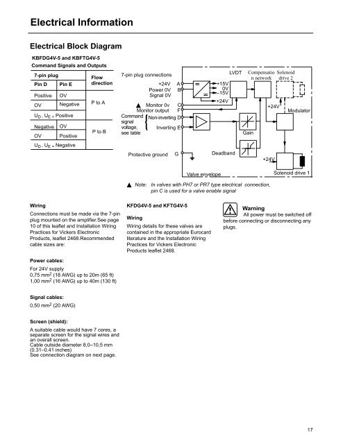
Electrical InformationElectrical Block DiagramKBFDG4V-5 and KBFTG4V-5Command Signals and Outputs7-pin plugPin DPositiveOVPin EOVNegativeU D - U E = PositiveNegativeOVOVPositiveU D - U E = NegativeFlowdirectionP to AP to B7-pin plug connections+24V APower 0V BSignal 0V Monitor 0v CMonitor output FCommandsignalvoltage,Non-inverting DInverting Esee tableProtective groundG+15V0V–15V+24VDeadbandLVDTCompensation networkGain+24V+24VSolenoiddrive 2ModulatorValve envelopeSolenoid drive 1 Note:In valves <strong>with</strong> PH7 or PR7 type electrical connection,pin C is used for a valve enable signalWiringConnections must be made via the 7-pinplug mounted on the amplifier.See page10 of this leaflet and Installation WiringPractices for <strong>Vickers</strong> ElectronicProducts, leaflet 2468.Recommendedcable sizes are:Power cables:For 24V supply0,75 mm 2 (18 AWG) up to 20m (65 ft)1,00 mm 2 (16 AWG) up to 40m (130 ft)KFDG4V-5 and KFTG4V-5WiringWiring details for these valves arecontained in the appropriate Eurocardliterature and the Installation WiringPractices for <strong>Vickers</strong> ElectronicProducts leaflet 2468.WarningAll power must be switched offbefore connecting or disconnecting anyplugs.Signal cables:0,50 mm 2 (20 AWG)Screen (shield):A suitable cable would have 7 cores, aseparate screen for the signal wires andan overall screen.Cable outside diameter 8,0–10,5 mm(0.31–0.41 inches)See connection diagram on next page.17