Proportional Directional Valves with Feedback Proportional ... - Vickers
Proportional Directional Valves with Feedback Proportional ... - Vickers
Proportional Directional Valves with Feedback Proportional ... - Vickers
- No tags were found...

You also want an ePaper? Increase the reach of your titles
YUMPU automatically turns print PDFs into web optimized ePapers that Google loves.
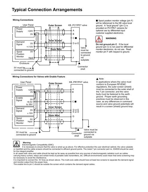
Typical Connection ArrangementsWiring ConnectionsPowerSupplyUser Panel+24V0VOuter ScreenKB..PC7/PE7 valveAB Spool position monitor voltage (pin F)will be referenced to the KB valve localground. A “local ground” (pin C) isprovided on PC7/PE7 versions foroptional use by differential inputcustomer supplied electronics.DemandSignalSpoolPositionMonitorEnclosure0V+/-10V0VInput0V must beconnected to groundInner ScreenDrain WireC D or EGFValvemust beconnectedto groundviasubplateConnectorshellWARNINGDo not ground pin C. If the localground (pin C) is not used for differentialmonitor electronics, do not use. Readmonitor pin F <strong>with</strong> respect to ground.Wiring Connections for <strong>Valves</strong> <strong>with</strong> Enable FeaturePowerSupplyEnableSignalDemandSignalSpoolPositionMonitorUser Panel+24V0V0V+8.5Vto 36V0V10V0VInputOuter ScreenInner ScreenDrain WireKB..PR7/PH7 valveABC D or EE or DGF Note:In applications where the valve mustconform to European RFI/EMCregulations, the outer screen (shield)must be connected to the outer shell ofthe 7 pin connector, and the valvebody must be fastened to the earthground. Proper earth groundingpractices must be observed in thiscase, as any differences in commandsource and valve ground potentials willresult in a screen (shield) ground loop.0V must beconnected to groundConnectorshellValve must beconnected toground viasubplateWarningElectromagnetic Compatibility (EMC)It is necessary to ensure that the valve is wired up as above. For effective protection the user electrical cabinet, the valve subplateor manifold and the cable screens should be connected to efficient ground points. The metal 7 pin connector part no. 934939 should be usedfor the integral amplifier.In all cases both valve and cable should be kept as far away as possible from any sources of electromagnetic radiation such as cablescarrying heavy current, relays and certain kinds of portable radio transmitters, etc. Difficult environments could mean that extra screening maybe necessary to avoid the interference.It is important to connect the 0V lines as shown above. The multi-core cable should have at least two screens to separate the demand signaland monitor output from the power lines.The enable line to pin C should be outside the screen which contains the demand signal cables.18