EasyScope User Manual - Kolter Electronic
EasyScope User Manual - Kolter Electronic
EasyScope User Manual - Kolter Electronic

Create successful ePaper yourself
Turn your PDF publications into a flip-book with our unique Google optimized e-Paper software.
DS2200C <strong>User</strong><strong>Manual</strong>Copyright (c) EasySync Ltd. 2003
<strong>EasyScope</strong> <strong>User</strong> <strong>Manual</strong>© 2003 ... USB-Instruments.comAll rights reserved. No parts of this work may be reproduced in any form or by any means - graphic, electronic, ormechanical, including photocopying, recording, taping, or information storage and retrieval systems - without thewritten permission of the publisher.Products that are referred to in this document may be either trademarks and/or registered trademarks of therespective owners. The publisher and the author make no claim to these trademarks.While every precaution has been taken in the preparation of this document, the publisher and the author assume noresponsibility for errors or omissions, or for damages resulting from the use of information contained in thisdocument or from the use of programs and source code that may accompany it. In no event shall the publisher andthe author be liable for any loss of profit or any other commercial damage caused or alleged to have been causeddirectly or indirectly by this document.
Table of ContentsContentsIPart I Introduction 31................................................................................................................................... Welcome to <strong>EasyScope</strong>32................................................................................................................................... Full Size Screen Image33................................................................................................................................... Screen Function Overview44................................................................................................................................... <strong>EasyScope</strong> Specification4Part II Installing <strong>EasyScope</strong> 51................................................................................................................................... Installing the Software5................................................................................................................................... 2 Installing the USB Drivers10Part III Using <strong>EasyScope</strong> 12................................................................................................................................... 1 The Run / Stop and Single Capture Buttons12................................................................................................................................... 2 TimeBase Settings13................................................................................................................................... 3 Offset Settings ( Ground Reference )14................................................................................................................................... 4 Selecting the Channel15................................................................................................................................... 5 Adjusting the Input Gain15................................................................................................................................... 6 AC/DC Coupling16................................................................................................................................... 7 Using the Trigger Functions17................................................................................................................................... 8 Voltage Measurement18................................................................................................................................... 9 Time / Frequency Measurement1910................................................................................................................................... XY Mode2111................................................................................................................................... Screen Colour Themes2212................................................................................................................................... Quitting the Application2413................................................................................................................................... Saving the Screen Image2514................................................................................................................................... Printing the Screen Image26Printer ......................................................................................................................................................... Setup2615................................................................................................................................... Customising the Display Colours2716................................................................................................................................... Customising the Background2917................................................................................................................................... Help Menus31Part IV Using the FFT Display 31................................................................................................................................... 1 FFT Display Overview31................................................................................................................................... 2 Saving the FFT33................................................................................................................................... 3 Printing the FFT34................................................................................................................................... 4 Closing the FFT Display34................................................................................................................................... 5 Other FFT Options35Changing ......................................................................................................................................................... the FFT Window35© 2003 ... USB-Instruments.com
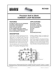
4 <strong>EasyScope</strong> <strong>User</strong> <strong>Manual</strong>1.3 Screen Function OverviewThe <strong>EasyScope</strong> screen is split into several functional areas as shown in the picture below. Thesections that follow illustrate how to use the settings to control the functions of the instrument.1.4 <strong>EasyScope</strong> SpecificationEASYSCOPE FEATURES· Attractive, easy to use visual display· Single and Dual Channel Display modes.· Sweep and XY display modes· F.F.T. ( Fast Fourier Transform ) display· TimeBase from 50uS/Div to 1.0 sec/div· Input Ranges from 0.1v / div to 5v / div· O.S.D. Markers for voltage measurement ( 2 sets )· O.S.D. Markers for time / frequency measurement· Save Oscilloscope Screens to Windows BMP files· Screen Printout Facility· AC / DC coupling support· Support for x1 / x10 probes· <strong>User</strong>-Defined Oscilloscope Display Colour Themes© 2003 ... USB-Ins truments.c om
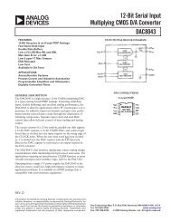
Installing <strong>EasyScope</strong>52 Installing <strong>EasyScope</strong>2.1 Installing the SoftwareBefore connecting the instrument to the PC, insert the supplied installation disk into the CD ROMdrive of your PC. The following menu will appear after a few seconds. Click on the "Install <strong>EasyScope</strong>1.0" button to launch the <strong>EasyScope</strong> installation program.Click on the "Install <strong>EasyScope</strong> 1.0" button to launch the <strong>EasyScope</strong> installation program. Thefollowing screen will appear ..© 2003 ... USB-Instruments.com
6 <strong>EasyScope</strong> <strong>User</strong> <strong>Manual</strong>Choose the language you would like the setup program to use. In this example we will selectEnglish. Click on the "Next" button to bring up the License Agreement Screen.© 2003 ... USB-Ins truments.c om
Installing <strong>EasyScope</strong>7If you agree with the terms and condiions of the License Agreement, check the "I agree" box andclick on the "Next" button to continue the installation process else click on the "Exit" button. The"Next" button is disabled if you do not agree to the terms and conditions. Agreeing to the terms andclicking on the "Next" button brings up the following screen.© 2003 ... USB-Instruments.com
8 <strong>EasyScope</strong> <strong>User</strong> <strong>Manual</strong>Select the directory you wish to install the <strong>EasyScope</strong> software into. A default directory is shown onthe screen. Unless you have good reason to change it we suggest you use the default suggested bythe installation program. Click on the "Start" button to commence copying the files to the<strong>EasyScope</strong> program directory.A progress screen ( above ) will appear as the files are installed. After a few seconds you should seethe Installation completed successfully message. Click on the "OK" button to complete the finalstage of the installation process.© 2003 ... USB-Ins truments.c om
Installing <strong>EasyScope</strong>9Finally, select if you wish to place a shortcut icon on the Windows desktop to the <strong>EasyScope</strong>program and click on "OK". The installation process is now complete. If you have selected thisoption, you can launch the <strong>EasyScope</strong> program from the desktop by double-clicking on the<strong>EasyScope</strong> icon ( pictured below ).You can also launch the <strong>EasyScope</strong> program from the Start -> Programs -> <strong>EasyScope</strong> menu onthe Windows Toolbar.As shown above, you also have access to the <strong>EasyScope</strong> Help File and Program Uninstaller fromthere.Before using <strong>EasyScope</strong> the USB drivers need to be installed. This is done by plugging in the© 2003 ... USB-Instruments.com
10 <strong>EasyScope</strong> <strong>User</strong> <strong>Manual</strong>instrument into a spare USB Port on the PC. The instrument should be plugged into a USB hub portof your PC or alternatively, a self-powered USB hub ( one that has it's own power supply ). If theinstrument consumes under 100mA ( check the specification ), you may also plug it into a buspoweredUSB Hub if desired.If this is the first time that the instrument has been plugged-in, Windows will then request the USBdrivers for your product. See Installing the USB Drivers 10 for further details.2.2 Installing the USB DriversBefore using <strong>EasyScope</strong> the USB drivers need to be installed. This is done by plugging in theinstrument into a spare USB Port on the PC. The instrument should be plugged into a USB hub portof your PC or alternatively, a self-powered USB hub ( one that has it's own power supply ). If theinstrument consumes under 100mA ( check the specification ), you may also plug it into a buspoweredUSB Hub if desired.If this is the first time that the instrument has been plugged-in, Windows will then request the USBdrivers for your product, Windows will request the USB drivers for your product and will display a AddNew Hardware Wizard dialog box. The examples below are for Windows '98 but the procedure is verysimilar for other Windows versions.Click on "Next" to bring up the following dialog box ...© 2003 ... USB-Ins truments.c om
Installing <strong>EasyScope</strong>11Click on "Next" to bring up the following dialog box ...Check "CD-ROM drive" and un-check any other options.NOTE : If the CD is not available and the <strong>EasyScope</strong> software has already been installed, thencheck the "Specify a location" box and use the Browse button to select the "drivers" sub-directory ofthe <strong>EasyScope</strong> Program Files directory instead.Keep Clicking on "Next" until the installation is finished as per the screen below.© 2003 ... USB-Instruments.com
12 <strong>EasyScope</strong> <strong>User</strong> <strong>Manual</strong>Click "Finish" and the driver installion is now complete.3 Using <strong>EasyScope</strong>3.1 The Run / Stop and Single Capture ButtonsOn starting <strong>EasyScope</strong>, the program is in idle mode and displays two buttons on the bottom toolbarwith the captions "Single" and "Run" In order to display a trace on the Oscilloscope you need toclick on either of the "Run" or "Single" buttons.The "Run" button is used to continuously capture and display data while the "Single" button capturesone screen's worth of data then returns the program to idle mode. On clicking the "Run" or "Single"buttons captured data will be displayed on the screen providing that -· One or Both of the channels are enabled AND Triggering is in auto mode ( = no triggering )AND / ORANDOR· Triggering is enabled on one of the channels AND the trigger level of the selected channel is within© 2003 ... USB-Ins truments.c om
Using <strong>EasyScope</strong>13the voltage range of the input signal.ANDWhen the "Run" button is clicked, the capture / display begins and the caption of the button changesto "Stop". The "Single" button is "greyed-out" as the two functions are mutually exclusive. To stopthe capture, click on the "Stop" button and the oscilloscope will change back into idle mode.The last captured data will remain displayed on the screen as long as the user does not change anyof the oscilloscope settings. If desired the screen display can be saved to a Windows Bitmap ( .bmp) format file or can be printed by any printer connected to the P.C. These subjects are dealt with inlater topics.An alternative to the Run / Stop button is provided through the File Menu at the top of the applicationscreen.Click on "File" to select the drop down menu ( below )Click on "Run" or "Stop" as desired.3.2 TimeBase SettingsThe timebase settings are adjusted by clicking on the rotary switch in the Timebase Panel. There are14 possible settings ranging from 50us per division ( fastest ) to 1sec / division ( lowest ) Pleasenote, at the lower speed settings there will be a noticeable delay between clicking on the "Run"button and the trace appearing on the oscilloscope screen. This is because the sampling (conversion ) rate is low and it takes more time to capture a buffer's worth of data.© 2003 ... USB-Instruments.com
14 <strong>EasyScope</strong> <strong>User</strong> <strong>Manual</strong>The timebase setting can change the sampling rate of the oscilloscope. The sampling rate isdisplayed on the bottom right of the oscilloscope panel - see below.3.3 Offset Settings ( Ground Reference )The ground ( 0v ) reference for each channel is shown by a small arrow on the left hand side of thescreen. The colour of the arrow is the same as the colour of the trace for that channel.To adjust the ground reference setting, click on the Up/Down buttons in the Offset Panel. There areone set of buttons for each channel - see below. The offset can be changed both in idle mode and inrun mode.© 2003 ... USB-Ins truments.c om
Using <strong>EasyScope</strong>153.4 Selecting the ChannelThe oscilloscope has two channels named CHA and CHB. These can be turned on and off byclicking on the two LED switches on the main panel. When a channel is enabled, the LEDs will belit, otherwise they will be dimmed. One or both channels must be enabled to view the oscilloscopetrace.In the example below, CHA is enabled and CHB is turned off.3.5 Adjusting the Input GainThe input gain is adjusted by clicking on the Volts/Div rotary switch on the main panel ( below ). Twoswitches are provided, the upper one sets the gain for CHA while the lower one sets the gain forCHB.© 2003 ... USB-Instruments.com
16 <strong>EasyScope</strong> <strong>User</strong> <strong>Manual</strong>There are 5 settings to choose from on each rotary switch. In addition, the settings depends on if theoscilloscope probe used is a x1 ( 1M ohm input impedance ) or a x10 ( 10M ohm input impedance ).If a x10 oscilloscope probe is used then enable the X10 setting for that channel by clicking on it'sX10 button. This will re-scale the switch and display cursor settings by a factor of 10. In thisexample, CHA is using a x1 oscilloscope probe, while CHB is using a x10 oscilloscope probe.3.6 AC/DC CouplingAC/DC coupling is controlled by miniature relays inside the oscilloscope. To select AC or DCcoupling click on the AC/DC selector switch for each channel. This will instruct the oscilloscope tochange the coupling from AC to DC or vice-versa. The current selection is highlighted in green to theright of the switch.In this example, CHA is set to DC coupling while CHB is set to AC coupling.© 2003 ... USB-Ins truments.c om
3.7 Using the Trigger FunctionsUsing <strong>EasyScope</strong>17Trigger functions are controlled by the controls on the right hand side of the main panel.To use triggering first of all select which channel ( CHA or CHB ) you wish to trigger from. If you donot use to use triggering select Auto instead and the oscilloscope trace will free-run.Next, select which edge of the signal you wish to trigger from - +ve selects a rising edge while -veselects a falling edge.Use the Trig Level Up/Down button to set the desired trigger level voltage. The trigger level is shownas an arrow with a "T" to the right of the oscilloscope screen.Finally,use the 10% / 50% / 90% switch to select the position of the triggerred event on the screen.In the following examples, we select to trigger from CHA on a rising edge.Example 1 - Trigger position set to 50%. In this example the trigger point ( the rising edge of thewaveform ) is set to the centre of the oscilloscope screen display.Example 2 - Trigger position set to 10%. In this case, the trigger is displayed towards the left side ofthe oscilloscope screen display.© 2003 ... USB-Instruments.com
18 <strong>EasyScope</strong> <strong>User</strong> <strong>Manual</strong>Example 3 - Trigger position set to 90%. In this case, the trigger is displayed towards the right sideof the oscilloscope screen display.3.8 Voltage Measurement<strong>EasyScope</strong> supports two pairs of cursors ( one for each channel ) for measuring amplitude.These areenabled / disabled by two buttons on the bottom panel.When a cursor is enabled a pair of measurement cursors ( dashed horizontal lines ) appear on thescreen. To the right of the cursors are marker blocks 1 and 2. To move a cursor, place the mousepointer over the marker block you wish to move, and holding down the left mouse button drag thecursor to the point you wish to measure.When a cursor is enabled, the measurement information for that cursor is displayed in an informationblock at the bottom of the trace display as shown below.C1 and C2 are the Cursor 1 and Cursor 2 values relative to the Ground Setting ( offset ) for thatchannel. The difference in amplitude ( C1 minus C2 ) is shown by the Delta value. The followingexample shows the cursors being used to measure the peak to peak amplitude of a signal- in this© 2003 ... USB-Ins truments.c om
Using <strong>EasyScope</strong>19case the 1KHz 1.25v square wave reference output of a DS2200 oscilloscope.The measurement cursors are placed, one on the top the other on the bottom of the waveform.As can be seen from the information display, Cursor 1 is sitting at 1.25v and Cursor 2 is sitting at 0vrelative to the Channel GND. The peak to peak amplitude is shown by the Delta value, in this case1.25 volts.An alternative to using the lower panel buttons is to click on the "Cursors" setting in the top menuand click on the item you wish to enable or disable.3.9 Time / Frequency Measurement<strong>EasyScope</strong> supports a pair of ( horizontal measurement ) cursors for measuring time / frequency.Note : Frequency can also be measured in a different way using the FFT display.To enable the time measurement cursors click on the Cur Horiz button.When a cursor is enabled a pair of measurement cursors ( dashed vertical lines ) appear on thescreen. At the top of the cursors are marker blocks 1 and 2. To move a cursor, place the mousepointer over the marker block you wish to move, and holding down the left mouse button drag thecursor to the point you wish to measure.A cursor information panel is displayed at the bottom of the oscilloscope screen showing the timevalue of each cursor and the difference.© 2003 ... USB-Instruments.com
20 <strong>EasyScope</strong> <strong>User</strong> <strong>Manual</strong>To display the delta as a frequency, click on the highlighted display area.The cursor information panel will now display the delta as frequency instead of time. In this case thefrequency is 2,000 Hz.The following example uses the time measurement cursors to measure the frequency of thecalibration reference output of a DS2000 oscilloscope. Cursor 1 is placed on the first falling edge ofthe waveform and Cursor 2 is placed on the next falling edge of the waveform.Looking at the cursor information panel ( in frequency mode ), we see that the frequency of the signalis in fact 1,000Hz or 1.0KHz.An alternative to using the lower panel buttons is to click on the "Cursors" setting in the top menuand click on the item you wish to enable or disable.© 2003 ... USB-Ins truments.c om
3.10 XY ModeUsing <strong>EasyScope</strong>21Easyscope has the capability of displaying in XY mode as well as sweep mode. XY mode is used tocompare the frequency and phase between two signals - usually sine waves. This kind of display issometimes referred to as a Lissajous figure. To change from sweep mode to XY mode, click on theXY button on the bottom panel.The following example shows two identical sine waves on each channel in sweep mode.Clicking on the XY button changes the display to XY Mode. The screen now looks like -© 2003 ... USB-Instruments.com
22 <strong>EasyScope</strong> <strong>User</strong> <strong>Manual</strong>As both the waveforms are identical XY mode just produces a straight line at 45 degrees. Moreinteresting effects can be obtained when the signals are out of phase ( an ellipse appears ) or whenthe frequencies are different ( an ellipse with a number of twists in it appears ).3.11 Screen Colour Themes<strong>EasyScope</strong> supports two different colour themes, "Normal" and "Bright". The two themes are toggledby clicking on the Illuminate button on the bottom panel. The colours of each theme can becustomised to the user's own preference. See the Changing the Screen appearance section fordetails of how to customise the theme colours.This is the default "Normal" colour theme. The background is black, the grid is green, CHA is shownin yellow and CHB is displayed in fuscia.© 2003 ... USB-Ins truments.c om
Using <strong>EasyScope</strong>23This is the default "Bright" screen. The grid colour changes from green to lime colour giving an effectsimilar to the illuminate button on a traditional oscilloscope.© 2003 ... USB-Instruments.com
24 <strong>EasyScope</strong> <strong>User</strong> <strong>Manual</strong>3.12 Quitting the ApplicationThere are two ways to shut down the <strong>EasyScope</strong> application. The first of these is to click on thesmall "X" button on the top right of the application screen.The other way to quit the application is through the File Menu at the top of the application screen.Click on "File" to select the drop down menu ( below )Click on "Exit" to quit the application.© 2003 ... USB-Ins truments.c om
3.13 Saving the Screen ImageUsing <strong>EasyScope</strong>25The image of the oscilloscope screen can be saved to a Windows BMP format file. This is donethrough the File Menu at the top of the application screen.Click on "Screen" to view the drop down menu ( below )Click on the "Save Screen Image to File" menu selection. This will bring up the "Save As" dialog box.By default, screen images are saved in the Images folder of the main application folder ( the folderthe <strong>EasyScope</strong> application was installed into ). A different folder can be selected if desired. Eitherenter a new file name in the box provided or click on an existing file name if you want to overwrite itwith the new image.Click on "Save" to save the screen image to a file or "Cancel" to quit without saving and return to theapplication.© 2003 ... USB-Instruments.com
26 <strong>EasyScope</strong> <strong>User</strong> <strong>Manual</strong>3.14 Printing the Screen ImageThe image of the oscilloscope screen can be printed to any installed Windows printer. This is donethrough the File Menu at the top of the application screen.Click on "Screen" to view the drop down menu ( below )Two choices are available. "Print Screen Image" prints out the Oscilloscope screen display only,while "Print Oscilloscope" prints out the whole application screen including all the panels, controlsand menus. Clicking on either of these will spool the selected image to the printer. If you have morethan one printer available, or you wish to change the printer properties ( settings ) review the PrinterSetup26topic before printing.3.14.1 Printer SetupThe image of the oscilloscope screen can be printed to any installed Windows printer. This is donethrough the File Menu at the top of the application screen.Click on "Screen" to view the drop down menu ( below )© 2003 ... USB-Ins truments.c om
Using <strong>EasyScope</strong>27If there is more than one printer attached to the PC and you do not wish to print to the default printerthen click on "Setup Printer" first to select which of the available printers you would like to use. Thisbrings up the standard Windows Print Setup dialog shown below.After changing the printer properties as desired, click on "OK" to select the new settings.3.15 Customising the Display ColoursThe display colours of the oscilloscope screen theme ( Normal or Bright ) can be changed from thedefault coluurs to suit the user preference. Once changed the theme colours are saved and will berestored on subsequent launces of the application. Changing the screen colours is done through theFile Menu at the top of the application screen.Click on "Screen" to view the drop down menu ( below )© 2003 ... USB-Instruments.com
28 <strong>EasyScope</strong> <strong>User</strong> <strong>Manual</strong>Placing the mouse cursor over the "Customise Screen Colours" entry will cuse a drop down submenuto appear as follows ..Choose the screen item you would like to change from the sub-menu and click on it to bring up thecolour selection dialog. Note : the colours can be reset to their default values at any time by clickingon the "Restore Default Colors" sub-menu item.If you require more than basic colours shown, click on "Define Custom Colors" to choose from awider selection. Once you have made your selection, click on the "OK" button to set the colour forthe chosen item.An example of an Oscilloscope Screen using alternative user-defined colours is shown below.© 2003 ... USB-Ins truments.c om
Using <strong>EasyScope</strong>293.16 Customising the BackgroundThe background image ( background colour plus grid ) of the oscilloscope screen can be saved to aWindows BMP format file, customised via a BMP editor such as Paint, Paintshop Pro etc withcustom text, logos etc and re-loaded into the application. This is done through the File Menu at thetop of the application screen.Click on "Screen" to view the drop down menu ( below )© 2003 ... USB-Instruments.com
30 <strong>EasyScope</strong> <strong>User</strong> <strong>Manual</strong>Click on "Save Background to File" to save the background. This brings up the Screen Save AsDialog box. The default folder for Screen background saves is the Screens folder in the applicationprogram main directory. Do NOT overwrite the two default theme screens DSNormal.bmp andDSBright.bmp as thse are re-created ( over-written ) every time the application is launched.In this case we will save the Normal screen background to file test1.bmp. We then edit test1.bmp, inthis case to include a custom header, then reload it using the "Load Background from File" option.The modified Oscilloscope screen now looks like this -Note : When editing the BMP file, do not alter the size of the image and do not change the file format© 2003 ... USB-Ins truments.c om
Using <strong>EasyScope</strong>31when saving the file. Doing so, can cause unpredictable results when running the application.3.17 Help Menus<strong>EasyScope</strong> provides built-in comprehensive access to both local and On-Line ( accessed via theInternet ) help.Clicking on the "Help" item of the menu bar displays the following options ...Clicking on the HTML Help option brings up the local help screen in Windows Compiled HTML (.CHM ) format. If it has been some time since your application software was installed check on theUSB Instruments Web Site to see if there is a newer version of the application software or help fileavailable for download.By clicking on "On-Line <strong>User</strong> <strong>Manual</strong>" you can view the latest version of the Help File on-line usingyour web browser. If you have any problems viewing the On-Line <strong>User</strong> <strong>Manual</strong>, check your browsersettings to make sure that javascript is enabled.By clicking on "On-Line F.A.Q." you can view the support Frequently Answered Questions on-lineusing your web browser. If you experience any problems, please check here first before contactingsupport. If you cannot find the answer to your query then Click Here ! to e-mail product support. Ifyou have any problems viewing the On-Line F.A.Q., check your browser settings to make sure thatjavascript is enabled.4 Using the FFT Display4.1 FFT Display Overviewwhile a normal Sweep oscilloscope display can be used to display waveforms in terms of time, it isalso possible to display the input waveforms in terms of frequency and magnitude by using a FFT (Fast Fourier transform ) algorithm on the input data. To enable FFT display on <strong>EasyScope</strong>, click onthe FFT button on the lower panel.This will bring up a second application window containing the FFT display of the input waveforms.© 2003 ... USB-Instruments.com
32 <strong>EasyScope</strong> <strong>User</strong> <strong>Manual</strong>The FFT displays frequency on the X-Axis and relative magnitude on the Y-Axis. The results of theFFT are automatically scaled so that the frequency with the highest amplitude equals 100% of the YAxis. It is possible to change this scaling manually by clicking on the "Man" button for that channeland using the Up/Down button to re-scale the Y-Axis manually.The display can show either channel or both channels simultaneously by clicking on the CHA / CHBLED buttons to enable or disable the display of that channel.For each channel, two cursors ( dashed lines ) are provided for measuring the Frequency anddisplaying it in an information box at the bottom of the display. To the top of the cursors are markerblocks 1 and 2. To move a cursor, place the mouse pointer over the marker block you wish to move,and holding down the left mouse button drag the cursor to the point you wish to measure.The above FFT display shows a 1kHz square wave input on channel A. Being a square wave, theharmonics can clearly be seen. In this example it is difficult to measure the frequency accurately asthe X-Axis stretches from zero to 100kHz.The X-Axis scaling depends on the sampling frequency of the oscilloscope. In the above case, theOscilloscope timebase was set to 200us / division which corresponds to a sample rate of 200,000samples / sec. To zoom in on the 1KHz peak, we will adjust the timebase ( on the main applicationscreen ) to 20ms / div which corresponds to a sampling rate of 10,000 samples / sec. The FFTdisplay now looks like this -© 2003 ... USB-Ins truments.c om
Using the FFT Display33By moving the measurement cursors, we can see that the main frequency is shown as 996 Hz andthe next harmonic is at 2998 Hz which, given the measurement resolution of the cursors is as closeas we can get to the true values of 1,000 Hz and 3,000 Hz.4.2 Saving the FFTThe image of the FFT screen can be saved to a Windows BMP format file. This is done through theFile Menu at the top of the application's FFT screen.Click on "File" to view the drop down menu ( below )Click on the "Save As" menu selection. This will bring up the "Save As" dialog box. By default,screen images are saved in the Images folder of the main application folder ( the folder the<strong>EasyScope</strong> application was installed into ). A different folder can be selected if desired. Either entera new file name in the box provided or click on an existing file name if you want to overwrite it withthe new image.© 2003 ... USB-Instruments.com
34 <strong>EasyScope</strong> <strong>User</strong> <strong>Manual</strong>Click on "Save" to save the screen image to a file or "Cancel" to quit without saving and return to theapplication.4.3 Printing the FFTThe image of the FFT screen can be printed to a Windows printer. This is done through the FileMenu at the top of the application's FFT screen.Click on "File" to view the drop down menu ( below )Click on the "Print" menu selection. This will spool the FFT image to the currently selected Windowsprinter.4.4 Closing the FFT DisplayTo close the FFT Display window click on the small "x" at the top-right of the application's FFTDisplay Window.© 2003 ... USB-Ins truments.c om
4.5 Other FFT Options4.5.1 Changing the FFT WindowUsing the FFT Display35The FFT screen display can changed to use a number of different windowing algorithms.Click on "FFT Window" to view the drop down menu ( below )The default window algorithm is "Rectangle". Others can be selected from the drop down menu ifrequired.4.5.2 Changing the FFT SpectrumThe FFT screen display can changed to use a number of different ways of scaling the Y_axis. Thesecan be changed from the memu at the top of the FFT display screen.Click on "Spectrum" to view the drop down menu ( below ).The default display algorithm is "Magnitude". Others can be selected from the drop down menu ifrequired.© 2003 ... USB-Instruments.com
36 <strong>EasyScope</strong> <strong>User</strong> <strong>Manual</strong>5 Appendix5.1 Error Messages5.1.1 FTD2XX DLL Not FoundIf when trying to run the <strong>EasyScope</strong> Application for the first time you get an "Error Starting Program"message as shown below, the reason is that you have not yet installed the USB drivers. Forinformation about installing the drivers read the Installing the USB Drivers 10 section then plug yourhardware into a spare USB Port.5.1.2 Device Not Found ErrorIf the following message is displayed when the Run / Stop ( or Single ) button is clicked the probablecause is that the USB Oscilloscope hardware is not connected to the computer. Check the hardwareconnection to USB. If you are connected to a self-powered USB hub, make sure it is powered up.5.2 Uninstalling The Software and DriversFrom the Start -> Programs -> <strong>EasyScope</strong> menu on the Windows Toolbal, select the UninstallOption and click on it.This will start the uninstaller program. The following confirmation screen will appear ...© 2003 ... USB-Ins truments.c om
Appendix37If you are sure you want to uninstall the <strong>EasyScope</strong> Program and USB drivers, click on "Yes". If not,click on "No" to abort the Uninstall process.Clicking on "Yes" brings up the following confirmation screen for the Uninstallation of the USBdrivers.If your USB Oscilloscope is still connected, please unplug it now. Click on "Continue" to uninstall theUSB Drivers.After the USB drivers have been uninstalled you should see the above screen. Click on "Finish" toproceed to the uninstallation of the <strong>EasyScope</strong> Application software. This will bring up the followingscreen.© 2003 ... USB-Instruments.com
38 <strong>EasyScope</strong> <strong>User</strong> <strong>Manual</strong>When the <strong>EasyScope</strong> Software is run for the first time, it automatically creates an INI file (easyscope.ini ) to store program settings and two BMP files ( DSBright.bmp and DSNormal.bmp )containing the images of the Normal and Bright screen themes. It is safe to delete these. In thecourse of using <strong>EasyScope</strong> the user may have saved some screen images and should decide if theywant to keep these or not. After deleting any unwanted files click on the "Close" button to finish theun-install procedure.© 2003 ... USB-Ins truments.c om
Index- A -AC/DC Coupling 16- B -Bright Colour Theme 22- F -Features 4FFT - Closing the display. 34FFT - Printing 34FFT - Spectrum 35FFT Display Overview 31File Menu - Cursors 18, 19File Menu - Exit 24File Menu - Run 12Index 39- C -Changing the Display Background 29Changing the Display Colours 27Channel Selection 15Colour Themes 22Cursors - Horizontal 19Cursors - Vertical 18- D -Display Background - Changing 29Display Colours - Changing 27DLL Not Found Error 36Driver Installation 10- E -Error Starting Program 36File Menu - Screen Options 22, 25, 27, 29File Menu - Stop 12Frequency Measurement 19Functional Overview 4- G -Ground Reference Settings 14- H -Help Menus 31- I -Illuminate Button 22Input Gain ( Adjusting ) 15Installalling the Software 5Installing the Drivers 10Introduction 3, 4© 2003 ... USB-Instruments.com
40 <strong>EasyScope</strong> <strong>User</strong> <strong>Manual</strong>- M -Measurement - Frequency 19Measurement - Time 19Measuring Amplitude 18- N -Normal Colour Theme 22- O -Offset Adjustment 14Overview - FFT 31- P -Printer - Setup 26Printing - Screen Image 26, 34- Q -Quitting the Application 24- R -Run / Stop Capture 12- S -Saving - Screen Image 25, 33Screen Colour Themes 22Screen Image - Printing 26, 34Screen Image - Saving to File 25, 33Settings - AC/DC Coupling 16Settings - Channel Selection 15Settings - Ground Reference 14Settings - Input Gain 15Settings - Timebase 13Settings - Trigger Functions 17Settings - XY Mode 21Setup - Printer 26Single Shot Capture 12Software Installation 5Specification 4- T -Time Measurement 19TimeBase Settings 13Trigger Functions - Settings 17- U -Uninstalling the application software 36Uninstalling the USB drivers 36<strong>User</strong> Screen ( Full Size ) 3Using <strong>EasyScope</strong> 12, 13, 14, 15, 16, 17, 18, 19,21, 22- V -Voltage Measurement 18- X -XY Mode 21© 2003 ... USB-Ins truments.c om