recommendation for the installation of profibus and worldfip ... - CERN
recommendation for the installation of profibus and worldfip ... - CERN
recommendation for the installation of profibus and worldfip ... - CERN
- No tags were found...

You also want an ePaper? Increase the reach of your titles
YUMPU automatically turns print PDFs into web optimized ePapers that Google loves.
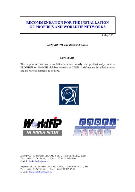
RECOMMENDATION FOR THE INSTALLATIONOF PROFIBUS AND WORLDFIP NETWORKS8 May 2001Jacky BRAHY <strong>and</strong> Raymond BRUNSUMMARYThe purpose <strong>of</strong> this note is to define how to correctly <strong>and</strong> pr<strong>of</strong>essionally install aPROFIBUS or WorldFIP fieldbus network at <strong>CERN</strong>. It defines <strong>the</strong> <strong>installation</strong> rules<strong>and</strong> <strong>the</strong> various elements to be used.7+(())(&7,9(),(/'%86Jacky BRAHY, Division LHC/IAS, <strong>CERN</strong>, 1211 GENEVE 23 (CH)Tel : 00 41 22 767 86 48, Fax : 00 41 22 767 95 80E-Mail : Jacky.Brahy@cern.chRaymond BRUN, Division LHC/IAS, <strong>CERN</strong>, 1211 GENEVE 23 (CH)Tel : 00 41 22 767 69 46, Fax : 00 41 22 767 95 80E-Mail : Raymond.Brun@cern.ch
SUMMARY• CABLES RECOMMENDED AT <strong>CERN</strong> : Page 3• WORLDFIP <strong>installation</strong> guide : Page 7• PROFIBUS <strong>installation</strong> guide : Page 232
CABLESRECOMMENDEDAT <strong>CERN</strong>Jacky BRAHY & Raymond BRUNLHC-IAS3
HALOGEN FREE CABLE COMMON TOPROFIBUS <strong>and</strong> WORLDFIP NETWORKSThe cables used must correspond to <strong>the</strong> characteristics defined in <strong>the</strong> st<strong>and</strong>ards in use<strong>and</strong> to <strong>the</strong> Safety Requirements at <strong>CERN</strong>.The colours are not imposed by <strong>the</strong> st<strong>and</strong>ards, but in order to better distinguish <strong>the</strong>networks installed at <strong>CERN</strong> it is preferable to respect <strong>the</strong> recommended colours.1) Colour <strong>of</strong> <strong>the</strong> cable : a colour by type <strong>of</strong> network• Purple <strong>for</strong> PROFIBUS• Green <strong>for</strong> WorldFIP• Blue <strong>for</strong> <strong>the</strong> (H1) instrumentation network with intrinsic protection <strong>for</strong>PROFIBUS PA <strong>and</strong> FIELDBUS-FOUNDATION (FF) which willprobably be <strong>the</strong> WorldFIP instrumentation bus.The transmission speed is 31.25 kbit/s.• Black <strong>for</strong> <strong>the</strong> (H1) instrumentation network without intrinsicprotection.Note : For in<strong>for</strong>mation, <strong>the</strong> colour orange is already reserved <strong>for</strong> <strong>the</strong> opticalcables <strong>and</strong> brown <strong>for</strong> ETHERNET.2) Main cable "Trunk"PROFIBUS DP (9,6 kHz to 12 Mhz)WorldFIP (1Mbit/s <strong>and</strong> 2.5Kbit/s)Impedance characteristic : 150 ΩCapacity :< 30 pf/mLine Impedance:≤ 110 Ω/kmWire Gauge :0.64 mmSection : > 0.34 mm 2Colour :• Outer covering : Purple <strong>for</strong> PROFIBUSGreen <strong>for</strong> WorldFIP• Conductors : Red <strong>and</strong> GreenWorldFIP & PROFIBUS are available permanently at <strong>the</strong> <strong>CERN</strong> store• under <strong>the</strong> SCEM : 04.21.60.020.4 <strong>for</strong> PROFIBUS• under <strong>the</strong> SCEM : 04.21.60.120.1 <strong>for</strong> WorldFIP3) Derivation cable <strong>for</strong> WorldFIP• One has to use 2 twisted pairs <strong>of</strong> armoured 150Ω cable <strong>and</strong> it shouldbe multistr<strong>and</strong>ed <strong>for</strong> <strong>the</strong> realisation <strong>of</strong> more flexible <strong>and</strong> "nonbreakable" Derivations.4
4) Cable <strong>for</strong> intrinsic protection (or not)<strong>for</strong> PROFIBUS PA <strong>and</strong> WorldFIP (FF) at 31.25kbit/sCharacteristic impedance: 100 ΩLine impedance :≤ 44 Ω/kmWire gauge :0.64 mmSection : > 0.8 mm 2Colour :Blue <strong>for</strong> EX(Explosive Environment)applicationsBlack <strong>for</strong> not EX applicationsReferences :• Belden : Cable PROFIBUS PA 3076F LSNH• Kerpen : Cable PROFIBUS PA FB-02YS(St+C)HNote :• These cables follow <strong>the</strong> IEC-1158-2 St<strong>and</strong>ard.• The Derivation cable is not selected <strong>for</strong> <strong>the</strong> moment.5
5) Tool <strong>for</strong> "Fast Connect" fast stripping <strong>of</strong> wiringThe tool "Fast Connect" makes it possible to quickly prepare <strong>the</strong> end <strong>of</strong> <strong>the</strong> cable tobe connected to <strong>the</strong> connector.This tool requires <strong>the</strong> use <strong>of</strong> a specific cable.References :• Tool : SCEM 34.94.36.320.2• Cable : St<strong>and</strong>ard at <strong>CERN</strong> under <strong>the</strong> references previously quoted.6
WorldFIP<strong>installation</strong> GuideRaymond BRUNLHC-IAS7
RECOMMENDATIONS FOR THE INSTALLATIONOF A WORLDFIP FIELDBUSFigure 1 shows <strong>the</strong> various elements <strong>of</strong> a st<strong>and</strong>ard WorldFIP fieldbus at <strong>CERN</strong>.PLCPremiumPCMCIA Module(TSXFPP10)Terminaison150 OHM(Acc7)11R(TSXFPCG10)3(Acc4)L3Boîtier deDérivation(Acc4)Boîtier deDérivation(Acc4)1Cable 1 paire torsadéeblindée 150 Ohm(Tronc)(Acc4)R11bTerminaison150 OHMEtancheMétallique+ 1 SUB_D9SUB_D9Femelle7L1(Acc2)L2EtancheMétallique+ 1 SUB_D9ConnecteurMétallique(Acc2)ConnecteurMétallique(Acc2)ConnecteurMétallique11aTerminaison150 OHM2Cable 2 pairestorsadées blindées150 Ohm(Dérivation)L n-1L nR(Acc7)(Acc2)Distance maxi : 5 Km théorique mais 1 Km conseilléeNota : La distance maxi est égale à la somme des distances L1 à LnBUS WorldFIP 1 MHz et 2.5 MHzFigure : 18
JUNCTION BOX "TAP" [Ref. 1]Reference mark 3 : Metal IP 65 derivation box. It has in addition one female 9 pinSUB-D9 <strong>for</strong> <strong>the</strong> connection <strong>of</strong> all <strong>the</strong> equipment being connected to <strong>the</strong> bus via aPCMCIA (TSXFPP10) card established in a Schneider PLC.Code : TSX FP ACC 4.CONNECTORReference mark 7 : SUB-D9 female connector <strong>and</strong> metal cap allowing connection inchain or derivation.Code. : TSX FP ACC 2LINE TERMINATORReference mark 11 : Its role is to adapt <strong>the</strong> end <strong>of</strong> <strong>the</strong> fieldbus to <strong>the</strong> characteristicimpedance (150Ω) in order to avoid any reflections. It can be established on <strong>the</strong>connector itself (Reference mark 11a) or in a distribution box (Reference mark 11b).Code : TSX FP ACC 79
"COPPER" BUS REPEATERReference mark 8 : The Schneider bus repeater is represented in figure 2.It makes it possible to increase <strong>the</strong> number <strong>of</strong> stations or <strong>the</strong> length <strong>of</strong> <strong>the</strong> fieldbus by<strong>the</strong> creation <strong>of</strong> additional segments with a 1000 metres maximum length. It is possibleto cascade a maximum <strong>of</strong> 4 repeaters allowing a fieldbus length <strong>of</strong> 5000m.Code : TSX FP ACC 6.Note : The repeater must be supplied with power <strong>and</strong> designed <strong>for</strong> a speed <strong>of</strong> 1Mbit/s.1000 m max32 Stations1000 m max32 Stations1000 m max32 Stations( 256 Stations Maxi)150 Ohm 150 Ohm150 Ohm150 Ohm11RRRR11RR150 Ohm88150 Ohm+/- 24V*+/- 24V*RepeteurRepeteur* Alimentation DC redressée mais non filtrée (+19 V à + 36 V )REPETEUR ELECTRIQUE 1 MHz SCHNEIDER( 32 Stations ou 1 Km )Figure : 210
Reference mark 12 : ditto <strong>for</strong> <strong>the</strong> Alstom repeater represented in figure 3.Code : RP131 / IR 155-1CIt must be supplied with 24V <strong>and</strong> designed <strong>for</strong> a speed <strong>of</strong> 2.5Mbit/s.Code : RP131 / IR 155-2CIt must be supplied with 24V <strong>and</strong> designed <strong>for</strong> a speed <strong>of</strong> 2.5Mbit/s.Note : Repeater RP131 can also function at 1Mbit/s <strong>and</strong> 31.25kbit/s700 m max32 Stations700 m max32 Stations700 m max32 Stations( 256 Stations Maxi)11 11150 OhmRRRR150 OhmSegment No 111 11150 Ohm12 IR155-2C 12 IR155-2CSegment No 3150 Ohm11R150 OhmSegment No 2R150 Ohm1112Répéteur RP131 / IR155-2C (48V) / IR155-1C (24V)REPETEUR ELECTRIQUE 2,5 MHz ALSTOM( 32 Stations ou 700 m )R. BRUN et D. GLENAT le : 4-4-2000Figure : 311
OPTICAL BUS REPEATERReference mark 9 : The optical repeater represented in figure 4, makes it possible tointerconnect 2 copper segments via an optical fibre which ensures good behaviour <strong>of</strong><strong>the</strong> fieldbus over long distances or <strong>for</strong> <strong>the</strong> connection <strong>of</strong> optical equipment.Code : TSX FP ACC 8M.Note : It must be powered like <strong>the</strong> copper repeater <strong>and</strong> designed <strong>for</strong> a speed <strong>of</strong>1Mbit/s.TerminaisonACC 7TerminaisonACC 711R11 11R11RR150 Ohm9Distancejusqu'à 30km9150 Ohm+/- 24V*+/- 24V*9Coupleur Cuivre / Optique* Alimentation DC redressée mais non filtrée (+19 V à + 36 V )Liaison OptiqueFigure : 412
CONNECTION RULESThe rules <strong>for</strong> connection <strong>of</strong> <strong>the</strong> active conductors <strong>and</strong> shielding are:• Connection <strong>of</strong> <strong>the</strong> conductors : See Appendix 1 <strong>and</strong> 2• Shielding <strong>and</strong> grounding <strong>of</strong> <strong>the</strong> fieldbus : See Appendix 2 <strong>and</strong> 3.• Minimum radius <strong>of</strong> curvature <strong>of</strong> <strong>the</strong> cable equal to ten times its diameter,that is 80 to 100mm.Note : O<strong>the</strong>r <strong>recommendation</strong>s relating to this chapter are detailed in two notes, onefrom Schneider [1], <strong>and</strong> <strong>the</strong> o<strong>the</strong>r from Alstom [2].SPEED AND DISTANCEAccording to <strong>the</strong> condition <strong>of</strong> use (environment, quality <strong>of</strong> <strong>the</strong> cable), <strong>the</strong> operationalmaximum distances will be <strong>the</strong> following ones:With a copper fieldbus• 31,25 kbit/s : from 5 to 20km• 1 Mbit/s : from 1 to 4km• 2.5 Mbit/s : from 500m to 1,5kmIn practice, to prevent any problems, <strong>the</strong> maximum distances selected are <strong>the</strong>following:• 31,25 kbit/s : 10km• 1 Mbit/s : 1km• 2.5 Mbit/s : 700mWith an optical fieldbus• 31,25 kbit/s, 1 Mbit/s <strong>and</strong> 2,5 Mbit/s : 40kmCONCLUSIONDuring all <strong>the</strong> LHC construction, <strong>the</strong> cables <strong>and</strong> distribution boxes relating to <strong>the</strong>WorldFIP fieldbus will be held in stock in <strong>the</strong> <strong>CERN</strong> store.REFERENCES[1] Schneider Electric :Plat<strong>for</strong>m <strong>of</strong> Automatism Premium / Catalogue August 99[2] Alstom-Cegelec / WorldFIP :Design <strong>and</strong> <strong>installation</strong> Manual / ALS 50414 b-en / edition 03-9813
Appendix 1 :Network <strong>of</strong> <strong>the</strong> WorldFIP laboratory(Example <strong>of</strong> connection <strong>and</strong> grounding)MBX 1000PC FIPDesignerModule microFIP CC131MaleMaleMalefemelle femelle femelleabpont de connexiondu blindageSUB DB 9 Femelle67+ -Au moins un point direct à la terreLes autres (le maximum) à traversun condensateur "haute tension"normalement implanté sur chaquemoduel WorldFIP(pont de connexion -a- ou -b-)ConnexionCâble WorldFIPSee also <strong>CERN</strong> WorldFIP site :http://wwwlhc.cern.ch/IAS/Frames/WS_Frames.html14
Appendix 2 :1- Preparation <strong>of</strong> <strong>the</strong> cables.Connection <strong>of</strong> fieldbus cable(Extracted from <strong>the</strong> " FIPIO Reference H<strong>and</strong>book ")• draw <strong>the</strong> cable over a length <strong>of</strong> approximately 5 cm,• Cut <strong>the</strong> braid at <strong>the</strong> level <strong>of</strong> <strong>the</strong> ground connection,• Set up <strong>the</strong> ground connection collar (<strong>the</strong> position <strong>of</strong> <strong>the</strong> collar on <strong>the</strong> cable musttake account <strong>of</strong> its fixing in <strong>the</strong> connector, on <strong>the</strong> right or on <strong>the</strong> left <strong>of</strong> <strong>the</strong> cable),• divide <strong>the</strong> strip iron <strong>and</strong> <strong>the</strong> colourless snap rings to release <strong>the</strong> conductors,• strip each conductor over a length <strong>of</strong> approximately 5 mm <strong>and</strong> equip <strong>the</strong>m with<strong>the</strong> ends provided.15
2- Connection <strong>of</strong> connectors TSX FP ACC2One distinguishes two kinds <strong>of</strong> connections <strong>for</strong> WORLDFIP/FIPIO equipment : in achain <strong>and</strong> as a derivation. The WorldFIP st<strong>and</strong>ard which defines <strong>the</strong> physical layerdoes not allow a "Pure electric derivation", so all WORLDFIP/FIPIO equipment iselectrically connected to <strong>the</strong> nearest <strong>the</strong> twisted pair.In <strong>the</strong> case <strong>of</strong> an <strong>installation</strong> requiring a derivation, this one will be obtained by a"return " cable (2 pairs <strong>of</strong> wires).16
Derivation ConnectionIn this drawing <strong>the</strong> cable 1 is a drop cable <strong>of</strong> type TSX FP CCxxx.If <strong>the</strong> derivation is carried out by 2 cables <strong>of</strong> type TSX FP CA/CR xxx, <strong>the</strong> connectionis <strong>the</strong> same one as <strong>for</strong> a chain. In this type <strong>of</strong> configuration, <strong>the</strong> cable can arriveindifferently by <strong>the</strong> left or <strong>the</strong> right-h<strong>and</strong> side, <strong>the</strong> bottom or <strong>the</strong> top.4 – Connection <strong>of</strong> <strong>the</strong> derivation box TSX FP ACC4The connection <strong>of</strong> <strong>the</strong> various cables is carried out by screw connector boxes, aconnector box per twisted pair. The implementation is <strong>the</strong> following :1 – open <strong>the</strong> derivation box,2 – prepare <strong>the</strong> cables as previously indicated <strong>the</strong>n make <strong>the</strong>m pass in <strong>the</strong> seal,3 – set up on each cable a ground collar. The position <strong>of</strong> <strong>the</strong> collar on <strong>the</strong> cablemust take account <strong>of</strong> its fixing in <strong>the</strong> case (on <strong>the</strong> right or on <strong>the</strong> left <strong>of</strong> <strong>the</strong>cable),4 – tighten each conductor in <strong>the</strong> screw connector block by respecting <strong>the</strong>pairing <strong>and</strong> <strong>the</strong> polarity <strong>of</strong> <strong>the</strong> conductors : Red (D+) / Green (D-) or Orange(D+) / Black (D-),5 – fix <strong>the</strong> ground collars <strong>the</strong>n tighten <strong>the</strong> seal passed by a cable or a terminator,6 – put back <strong>the</strong> lid <strong>and</strong> fix it.The TSX FP ACC4 derivation box also has a 9 pin female connector which allows <strong>the</strong>connection :- <strong>of</strong> a terminal provided with a card : TSX FPC 10 or FCP FPC 10 <strong>and</strong> <strong>of</strong> its wire <strong>of</strong>connection wire TSX FP CE 030,- <strong>of</strong> an equipment provided with a PCMCIA type 3 card : TSX FPP 10, TSX FPP 20,or FCP FPC 10 <strong>and</strong> <strong>of</strong> its connection wire TSX CG 010 / 030.The diagrams hereafter show <strong>the</strong> various types <strong>of</strong> possible connections :18
• chaining carried out with trunk cable,• connection <strong>of</strong> a TSX FP ACC7 terminator,• st<strong>and</strong>by box,• derivations carried out with drop cable.Chaining carried out with <strong>the</strong> trunk TSX FP CA/CRxxx cableIn this case, <strong>the</strong> derivations must beconnected as indicated here.The user will be able to also connect aprogramming terminal on <strong>the</strong> Sub-Dconnector after having removed <strong>the</strong> stopper aquarter <strong>of</strong> a turn.Connection <strong>of</strong> a TSX FP ACC7 terminatorIf <strong>the</strong> derivation box is at <strong>the</strong> beginning or<strong>the</strong> end <strong>of</strong> <strong>the</strong> segment, only <strong>the</strong> cable T1 isconnected <strong>and</strong> a non polarised TSX FPACC7 terminator is connected in place <strong>of</strong><strong>the</strong> second section <strong>of</strong> <strong>the</strong> cable.The connection is carried out, according towhe<strong>the</strong>r <strong>the</strong> derivation box is on st<strong>and</strong>by orthat a derivation is already cabled, asindicated below. The user will be able toalso connect a programming terminal on<strong>the</strong> Sub D connector after having removed<strong>the</strong> stopper a quarter <strong>of</strong> a turn.St<strong>and</strong>by box, "cabled chaining" box19
1 Main TSX FP CA/CRxxx,5 TSX FP ACC7 terminator,(+) Corresponds to <strong>the</strong> red or orange wire,(-) Corresponds to <strong>the</strong> green or black wire.TSX FP ACC7 terminator, ACC420
Cabled derivation box1 Main cable TSX FP CA/CRxxx,2 Branch cable TSX FP CCxxx,5 TSX FP ACC 7 terminator.(+) Corresponds to <strong>the</strong> red or <strong>the</strong> orange wire,(-) Corresponds to <strong>the</strong> green or <strong>the</strong> black wire.Power Supply which resists RadiationThe figure below represents simple powering which resists radiation. It is used on <strong>the</strong>Schneider PLCs tested in <strong>the</strong> radiation zone in TCC2.Diode SI. REDR. GBPC220 V AC18 V ACCondensateur Alu.ELC. Fix.CE :40V : 10000 MF26 V-DCTransfo Torique :220V/ 2x 10-12-15V 2,5AAlimentation testée et résistant aux Radiations21
Appendix 3 :TrunkShielding <strong>and</strong> grounding <strong>of</strong> <strong>the</strong> WorldFIP Fieldbus(ALSTOM Recommendation)TrunkTrunkLinTerminatLinTerminatDropDropPinPinPinPin22
PROFIBUSInstallation GuideJ. Brahy LHC-IAS23
See also:Guides <strong>of</strong> PROFIBUS national organisationPROFIBUS Technical Guideline-Installation Guideline <strong>for</strong> PROFIBUS DP N° 2.112PROFIBUS Guideline – PROFIBUS Interconnection Technology N° 2.142The Siemens h<strong>and</strong>bookSIMATIC NET PROFIBUS Network Ref. 6GK1970-5CA20-0AA024
PROFIBUS DPAuthorised distances according to <strong>the</strong> transmission speed.Flows (kbits/s) 9.6 19.2 19.2 45.45 93.75 187.5 500 1500 3000 6000 12000Lengthsegment (m)1200 1200 1200 1200 1200 1000 400 200 100 100 100Maximum number <strong>of</strong> stations by segment : 32Network example:The elements which are <strong>the</strong> subject <strong>of</strong> a <strong>recommendation</strong> in a network DP are- <strong>the</strong> active termination- The connectors (bus connector or bus terminal)- The cable (see chapter « recommended cables at <strong>CERN</strong> »)- The repeatersActive termination :The bus is supplied by <strong>the</strong> stations placed at each end, which can cause problems in<strong>the</strong> event <strong>of</strong> intervention on <strong>the</strong> last station. To avoid that, it is recommended to usean active termination at <strong>the</strong> end <strong>of</strong> <strong>the</strong> line.Siemens reference :Active element <strong>of</strong> termination <strong>for</strong> PROFIBUS6ES7 972-0DA01-0AA025
Bus connector:The bus connector is placed directly on <strong>the</strong> decentralised system or <strong>the</strong> master. It canreceive two cables <strong>for</strong> wiring in « daisy chain » .There is a version without end <strong>of</strong> line terminating resistor <strong>and</strong> <strong>the</strong> version withterminating resistor <strong>of</strong> end <strong>of</strong> line. The latter although not necessary <strong>for</strong> <strong>the</strong>intermediate stations is never<strong>the</strong>less recommended because <strong>the</strong> use <strong>of</strong> <strong>the</strong> terminationcauses <strong>the</strong> insulation <strong>of</strong> <strong>the</strong> more distant stations, this insulation <strong>of</strong> <strong>the</strong> part which isdownstream from <strong>the</strong> finished connector facilitates <strong>the</strong> progressive commissioning <strong>of</strong><strong>the</strong> <strong>installation</strong> <strong>and</strong> <strong>the</strong> search <strong>for</strong> problems on <strong>the</strong> bus.There is also a version with extra socket ; it makes it possible to connect a console <strong>of</strong>programming <strong>for</strong> tests or breakdown service without having to stop <strong>the</strong> bus.To use when this need is expressed.The recommended connectors are <strong>of</strong> type « Fast Connect » :Without extra socket: Siemens 6ES7 972-0BA50-0XA0With extra socket: Siemens 6ES7 972-0BB50-0XA0Convention <strong>of</strong> wiring :Connector limit A Green conductorConnector limit B Red conductorPreparation <strong>of</strong> <strong>the</strong> cable <strong>for</strong> connector « Fast Connect »Foot note : It is not necessary to strip <strong>the</strong> end <strong>of</strong> <strong>the</strong> wires.26
Bus terminal 12M:One can use this means <strong>of</strong> connection when it is difficult to bring <strong>the</strong> bus cabledirectly on <strong>the</strong> <strong>of</strong>f-set equipment.Like <strong>for</strong> <strong>the</strong> bus connector, <strong>the</strong> use <strong>of</strong> <strong>the</strong> terminating resistor isolates <strong>the</strong> rest <strong>of</strong> <strong>the</strong>network.The length <strong>of</strong> <strong>the</strong> connection cable to <strong>the</strong> final equipment is 1.5m.The final equipment must deliver 90mA under 5V <strong>for</strong> <strong>the</strong> power supply <strong>of</strong> <strong>the</strong> busterminal 12M.It is possible to connect 32 BT12M to <strong>the</strong> maximum on a bus segment.Siemens reference :Bus terminal 12M <strong>for</strong> PROFIBUS 6GK1 500-0AA10Cable preparation <strong>for</strong> bus terminal <strong>and</strong> repeater connection.27
Equipment list supporting <strong>the</strong> bus terminal 12MRepeater :If <strong>the</strong> distances are higher than those which are authorised <strong>for</strong> a segment, one must userepeaters.The maximum number is 9 or 10 segments.Siemens reference :RS 485 Repeater <strong>for</strong> PROFIBUS6ES7 972-0AA01-0XA028
PROFIBUS PATransmission speed: 31.25kbits/sMaximum length <strong>of</strong> a segment : 1900mParticularity <strong>of</strong> PROFIBUS PAThe bus cable transports <strong>the</strong> power supply <strong>and</strong> <strong>the</strong> communication.Maximum current <strong>of</strong> power supply circulating in <strong>the</strong> cable:Ex Zone100mANon Ex zone 400mALength <strong>of</strong> <strong>the</strong> branch cablesNumber <strong>of</strong> branch cables Maximum length <strong>of</strong> a branchcableCoupler DP/PACoupler DP/PA Ex1 to 12 Maximum 120 m Maximum 30m13 to 14 Maximum 90 m Maximum 30m15 to 18 Maximum 60 m Maximum30m19 to 24 Maximum 30 m Maximum 30mOne uses <strong>the</strong> same cable <strong>for</strong> <strong>the</strong> trunk <strong>and</strong> derivations.29
The elements which are <strong>the</strong> subject <strong>of</strong> a <strong>recommendation</strong> in a st<strong>and</strong>ard PA networktype are- connections- terminators- <strong>the</strong> cable (see chapter « Cables recommended at <strong>CERN</strong>)Components <strong>for</strong> PROFIBUS PA30
Networks with optical fibre.Under certain conditions- noisy environment- long distances- ground problemsit is possible to use an optical network. One <strong>the</strong>n uses OLM (Optical Link Module)OLM :The OLM have an electric channel with floating contact (as on a repeater) <strong>and</strong>,according to <strong>the</strong> model one or two optical channels.The OLM are conceived transmission speeds <strong>of</strong> 9,6kbit/s to 12Mbits/s. Thetransmission speed is automatically detectedLinear topology example with OLM32
Redundant optical rings with OLMThe redundant optical rings are a particular <strong>for</strong>m <strong>of</strong> linear topology. The « looping »<strong>of</strong> <strong>the</strong> optical line in a ring endows on <strong>the</strong> network with a great reliability.Components <strong>for</strong> optical network :Cables with optical plastic fibreProperties <strong>of</strong> cables with optical plastic fibre.33
Glass Fibre-Optic cablesProperties <strong>of</strong> glass fibre-optic cables35
The OLM exist in versions with one or two optical interfaces <strong>for</strong> various types <strong>of</strong>FO cable :- Plastic FO cables (980/1000 µm) can be used to a length <strong>of</strong> section <strong>of</strong> 80m. Theycan be equipped with BFOC connectors on site.- PCF FO cables (200/300 µm) can be used to a length <strong>of</strong> section <strong>of</strong> 400m. Theycan be equipped with 4 BFOC connectors <strong>and</strong> a polling loop.- The cables with multimode glass optical fibres (62,5/125 µm) are usable to coverdistances up to 3000m. . They can be equipped with 4 BFOC connectors- The cables with monomodes glass optical fibre (10/125 µm) are usable <strong>for</strong> verylong distances up to 15 km.36
OLM modules available at Siemens.Number <strong>of</strong> ports <strong>and</strong> distances usable <strong>for</strong> <strong>the</strong> different OLM.37
AcknowledgmentsR. RAUSCH <strong>for</strong> his constructive advice <strong>and</strong> his rich person experiment on <strong>the</strong>fieldbuses componentsA. BLAND <strong>for</strong> his assistance in <strong>the</strong> correction <strong>of</strong> <strong>the</strong> English document38