PDF PDF.
PDF PDF.
PDF PDF.
- No tags were found...

You also want an ePaper? Increase the reach of your titles
YUMPU automatically turns print PDFs into web optimized ePapers that Google loves.
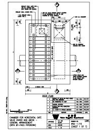
- 5 installed at the entry point next to the flowmeter inside a combined chamber ina by-pass arrangement to the main water main.Similar to DMAs, details of any mainlaying works which may affect theoperation or even integrity of existing PMAs should be provided to the WaterLoss Management Section of Development (1) Division for comments duringthe design stage of a new mainlaying project.1.3 Operational Requirements1.3.1 Designers should, in consultation with the relevant Regional Office,Development (1) Division and other divisions/units of WSD as appropriate,provide sufficient valves along the proposed water mains to suit operationaland maintenance requirements. Different types of valves commonly used byWSD in the water supply network are given below for reference. Flowmeters,multi-purpose inspection chambers, critical pressure points and contact pointsfor leak noise correlation, which are used by WSD for district metering,pressure management or leak detection, are also described briefly below.1.3.2 Sectional ValvesSectional valves are gate (or sluice) valves used to isolate sections of apipeline in an emergency or for maintenance and repair. They should beinstalled along a pipeline at a spacing from 300 m to 800 m. It should benoted that gate valves are suitable for isolation of a pipeline in either “fullyopen” or “fully close” positions, but not for frequent open/close operation andflow regulation. Whenever possible, valves should not be positioned at roadjunctions or in heavily trafficked areas to avoid disruption to traffic during theconstruction and operation in valve chambers.Valves of DN100 to DN300 should be vertical valves. See StandardDrawing WSD 1.10 for details of the valve chambers. Valves of DN400 orabove should be horizontal valves. Vertical valves of diameter DN400 orabove should be used only if there is no space for construction of horizontalvalve chamber. See Standard Drawings WSD 1.11 and 1.12 for details ofhorizontal valve chambers and WSD 1.46 and 1.47 for details of vertical valvechambers.All valves should be ordered with nominal pressure rating PN16 unless inspecial circumstances where higher pressure rating is required. As a normalpractice, valves of DN600 or above should be provided with an externalby-pass arrangement to link up the upstream and downstream sides of thevalves (see Standard Drawing WSD 1.11 and Appendix 1.3 of CivilEngineering Design Manual Volume II). These valves should not be fitted