Monitoring Battery System for Electric Vehicle, Based On “One Wire ...
Monitoring Battery System for Electric Vehicle, Based On “One Wire ...
Monitoring Battery System for Electric Vehicle, Based On “One Wire ...

Create successful ePaper yourself
Turn your PDF publications into a flip-book with our unique Google optimized e-Paper software.
<strong>Monitoring</strong> <strong>Battery</strong> <strong>System</strong> <strong>for</strong> <strong>Electric</strong> <strong>Vehicle</strong>,<br />
<strong>Based</strong> <strong>On</strong> “<strong>On</strong>e <strong>Wire</strong>” Technology<br />
Javier Ibáñez Vial<br />
Department of <strong>Electric</strong>al Engineering<br />
Pontificia Universidad Católica de Chile<br />
Santiago, Chile<br />
jibanezv@puc.cl<br />
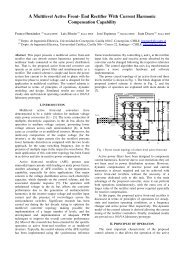
Abstract— A monitoring system <strong>for</strong> a battery powered electric<br />
vehicle (EV) has been implemented and tested. The system allows<br />
voltage end temperature monitoring of each one of the 24<br />
batteries. Besides, the system will also allow monitoring the<br />
energy delivered by a photovoltaic cell which is being<br />
implemented on the roof of the vehicle. The monitoring method<br />
uses digital sensors with technology “<strong>On</strong>e <strong>Wire</strong>”®, which allows<br />
transmitting data from all batteries through a serial bus. The<br />
in<strong>for</strong>mation is shown in a LCD screen with 320x340 pixel<br />
resolution. The paper explains the main characteristics of the<br />
system and shows some photographs and some experimental<br />
results through the in<strong>for</strong>mation given by the LCD screen<br />
I. INTRODUCTION<br />
As the result of new developments on experimental batterypowered<br />
electric vehicles, the need <strong>for</strong> fast in<strong>for</strong>mation related<br />
to different components and equipment emerges, especially<br />
data related to battery life and knowledge about the overall<br />
system efficiency. Also, the capability of preventing fires and<br />
explosions produced by the bad operation of individual<br />
batteries is required. Then, it becomes essential having specific<br />
data-monitoring and data-logging systems to acquire this<br />
in<strong>for</strong>mation. Specially, in the case of batteries, individual<br />
voltages and temperatures are necessary to identify. There<br />
becomes visible the problem of different voltage reference<br />
levels and the need <strong>for</strong> galvanic isolation. In this way, each<br />
battery can be replaced in case of failure and it is possible to<br />
view the conditions of the charging/discharging process.<br />
The classical method to measure voltage and temperature in<br />
a battery pack inside an EV, is based on implementing voltage<br />
and temperature sensors <strong>for</strong> each one of the batteries [1]. These<br />
sensors (with an appropriate galvanic isolation <strong>for</strong> voltage<br />
measurements) produce analog signals which are individually<br />
transmitted to a central management system, then converted to<br />
digital signals and processed by a microprocessor. The<br />
microprocessor makes the appropriate calculations to show the<br />
in<strong>for</strong>mation on a screen or store it <strong>for</strong> later analysis. However,<br />
two problems arise in the design of this monitoring method:<br />
electromagnetic interference (EMI), and the huge amount of<br />
wires required <strong>for</strong> its implementation. These problems become<br />
complicated because of difficulty in noise isolation and<br />
hardware management (too many shielding wires) [2]. Besides,<br />
Juan W. Dixon, Ph.D.<br />
Department of <strong>Electric</strong>al Engineering<br />
Pontificia Universidad Católica de Chile<br />
Santiago, Chile<br />
jdixon@ing.puc.cl<br />
the system obviously needs multiplexers to control every signal<br />
coming from each one of the individual batteries in the string.<br />
This work presents a different approach: sequential<br />
monitoring with only “one wire”, using special integrated<br />
sensors designed with individual identifications. The system<br />
implemented does not allow a balanced charging/discharging<br />
of the batteries, but it can be the base of it.<br />
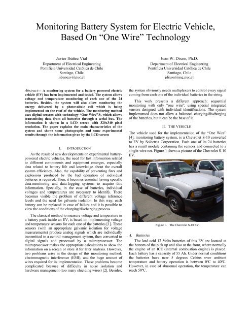
II. THE VEHICLE<br />
The vehicle used <strong>for</strong> the implementation of the “<strong>On</strong>e <strong>Wire</strong>”<br />
[4], monitoring battery system, is a Chevrolet S-10 converted<br />
to EV by Solectria Corporation. Each one of its 24 batteries<br />
has a small module containing the sensors and connected to a<br />
single-wire net. Figure 1 shows a picture of the Chevrolet S-10<br />
EV.<br />
Figure 1. The Chevrolet S-10 EV.<br />
A. Batteries<br />
The lead-acid 12 Volts batteries of this EV are located at<br />
the bottom of the pick up and also at the front, where normally<br />
the engine of an ICE (internal combustion engine) is placed.<br />
Each battery has a capacity of 55 Ah. Under normal conditions<br />
the batteries have near 5 degrees Celsius over ambient<br />
temperature and battery operation is between 0ºC to 40ºC.<br />
However, in case of abnormal operation, the temperature can<br />
reach 50ºC.
The voltage of the batteries is normally between 12 to 13<br />
Volts. When the battery is in good conditions, but discharged,<br />
the voltage can be 11.5 Volts. If the battery gets out of this<br />
range it has a problem inside it. The location of the batteries<br />
inside the vehicle is displayed in Figures 2 and 3.<br />
Figure 2. Batteries at the front<br />
MICROCONTROLLER<br />
RS232 RS232<br />
LCD Display &<br />
Touch Screen Controller<br />
DS2480B<br />
Bus Driver<br />
Touch<br />
Screen<br />
RGB<br />
Screen<br />
Figure 3. Batteries at the rear<br />
III. HARDWARE IMPLEMENTATION<br />
Figure 4 shows a diagram of the monitoring and logging<br />
system.<br />
sensor<br />
sensor<br />
sensor<br />
Figure 4. <strong>Monitoring</strong> system<br />
Galvanic<br />
Isolation<br />
Galvanic<br />
Isolation<br />
Galvanic<br />
Isolation<br />
<strong>Battery</strong><br />
<strong>Battery</strong><br />
<strong>Battery</strong>
As already mentioned, this paper presents a sequential<br />
monitoring system with just one wire, and digital data<br />
transmission instead of analog. This alternative asks <strong>for</strong><br />
special semiconductors, capable of sending the captured<br />
in<strong>for</strong>mation from each battery to the microprocessor. In this<br />
work, a special integrated sensor from Dallas<br />
Semiconductor, designed <strong>for</strong> monitoring purposes in small<br />
equipment has been used: the DS2436 [6].<br />
A. The DS2436 sensor<br />
The digital sensor DS2436 measures temperature and<br />
voltage. It has only three terminals: supply, ground and<br />
communication port. The communication port is common to<br />
all sensors, no matter the quantity. They are connected to the<br />
same wire and finally to a resistance-pulled-up driver. The<br />
bus has a master-slave configuration, where the master could<br />
be a computer or microprocessor, and the sensors are the<br />
slaves. Eventually different sensor types could be added to<br />
the bus, even actuators such as digital potentiometers. In this<br />
particular application only the DS2436 sensor was used.<br />
Each sensor has a unique identification number assigned by<br />
the manufacturer, which is used to send commands to a<br />
particular sensor. These commands include voltage or<br />
temperature conversion and storing or sending the associated<br />
data. The same bus is used to send commands and receiving<br />
data, as a bidirectional path. Each voltage or temperature<br />
conversion takes about 10 ms. Figure 5 shows a detail of the<br />
sensors in a couple of batteries.<br />
Figure 5. A detail of the battery sensors<br />
Communication between microprocessor can be achieved<br />
connecting directly the processor to the bus and respecting<br />
<strong>On</strong>e <strong>Wire</strong> protocol timing or through the processor’s serial<br />
port using a bus driver. The integrated circuit DS2480 is a<br />
bus driver that converts <strong>On</strong>e <strong>Wire</strong> protocol into RS232 and<br />
vice versa at speeds up to 115200 bps. In this case the bus<br />
driver was used.<br />
B. Other system requirements<br />
The sensor itself is not enough to capture data from<br />
series-connected batteries, because ground of every sensor<br />
must be connected together as the bus’s reference. Hence an<br />
isolation circuit must be added between the sensor and<br />
battery terminals, to modules installed in each battery. This<br />
isolation can be achieved via signal trans<strong>for</strong>mers, voltage<br />
LEMs or optocouples. The third option was selected because<br />
of the easier implementation and lower space<br />
requirements[3]. The circuit used <strong>for</strong> galvanic isolation is<br />
shown in Fig. 6.<br />
Figure 6. Galvanic isolation with optocouples<br />
Nevertheless, the optocouple must be linearized, so the<br />
analog voltage transmitted is properly measured. The<br />
SLC800 optocouple, from Solid State Optronics, is an<br />
appropriated element that can be easily linearized via<br />
feedback circuit. It has two application modes:<br />
photoconductive or photovoltaic operation. In this case it<br />
was more appropriate to use it in the photovoltaic mode.<br />
It is also desirable that data can be stored in a memory so<br />
it can be analyzed afterwards. The ideal case would be the<br />
possibility to store voltage and temperature data from a<br />
complete charge and drive cycle, at small time intervals.<br />
C. Specific Characteristics<br />
The particular implementation consists of 24 sensor<br />
modules, each with DS2436 sensor, a SLC800 optocouple<br />
<strong>for</strong> galvanic isolation; these modules are connected to a <strong>On</strong>e<br />
<strong>Wire</strong> bus, which is interfaced to a microprocessor PIC<br />
16F877A by a DS2480B bus driver [5]. The microprocessor<br />
sends commands to the sensors and receives data from them<br />
[4]. The bus driver translates commands and data to and<br />
from RS232 to <strong>On</strong>e <strong>Wire</strong> protocol. Figure 7 shows the<br />
sensors arrangement over the batteries of Fig. 3, and Fig. 8<br />
displays the printed board with the microprocessor.<br />
Figure 7. Sensors arrangement at the back of EV.
Figure 8. Printed board with microprocessor.<br />
The processor shows data on a 7” screen in real time and<br />
interacts with the user through a touch-screen, which are<br />
shown in Figs. 9a) and 9b).<br />
Figure 9. Touch-screen display inside the vehicle<br />
The vehicle also has a solar-cell group, which’s energy<br />
contribution is measured and shown on screen. This<br />
a)<br />
b)<br />
in<strong>for</strong>mation is measured by the microprocessor via the A/D<br />
converter.<br />
Voltage, temperature and solar cell data is stored every<br />
10 seconds. All of this in<strong>for</strong>mation is stored in a 1 MB flash<br />
memory BQ4016Y, which is also controlled by the PIC<br />
microprocessor.<br />
IV. EXPERIMENTAL RESULTS<br />
The experimental results obtained fulfills with the<br />
requirements of the system. The objective of the<br />
implementation is the behavior of each battery of the EV.<br />
The communications of the system works well, without<br />
errors. The tests done to the system guarantees an error rate<br />
of one in a million.<br />
The refresh speed of the measures satisfies the<br />
requirements of a monitoring system. The driver can see<br />
each five second the behavior of each battery, but this speed<br />
is not enough if a control system is required. In this case, the<br />
solutions are operating with a higher speed in the <strong>On</strong>e <strong>Wire</strong><br />
bus and use a faster microcontroller.<br />
The next figures show some experimental results<br />
obtained with the LCD screen installed inside the vehicle.<br />
<strong>On</strong>ce activated, the touch-screen displays five options:<br />
<strong>Battery</strong> Voltage (Voltaje), <strong>Battery</strong> Temperature<br />
(Temperatura), power and energy delivered by the solar cells<br />
(Celdas), Record Data (Grabar), and screen contrast<br />
(Contraste).<br />
Figure 10 shows the screen related with the photovoltaic<br />
cells. This screen gives in<strong>for</strong>mation of the instantaneous<br />
power delivered and the energy stored in the batteries after a<br />
defined period of time (in Spanish: Tiempo transcurrido<br />
aproximado). The grey button at the right of the touch-screen<br />
(Reiniciar Tiempo) allows resetting the energy data.<br />
Figure 10. Screen related with photovoltaic cells in<strong>for</strong>mation<br />
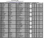
Figure 11 shows in<strong>for</strong>mation related with the individual<br />
voltage in each one of the 24 batteries of the EV. The range<br />
of measuring is 10 to 15 Volts. The green columns allow the
comparison between battery voltages. Numerical value of<br />
each voltage can be read at the bottom of the screen. It can<br />
be appreciated in the figure that battery number two is low in<br />
voltage related to the other batteries and probably it needs to<br />
be revised.<br />
Figure 11. Screen related with battery voltages in<strong>for</strong>mation<br />
Finally, Figure 12 shows a similar bar in<strong>for</strong>mation <strong>for</strong> the<br />
battery temperatures. The range of measure is 0 to 50 ºC.<br />
Figure 12. Screen related with battery temperatures.<br />
V. CONCLUSIONS<br />
A monitoring system <strong>for</strong> a battery powered electric<br />
vehicle (EV) was implemented and tested. The system<br />
allows voltage end temperature monitoring of each one of<br />
the 24 batteries, which allows to detect early problems or<br />
failures in individual batteries. Besides, the system will also<br />
allow monitoring the energy delivered by a photovoltaic cell<br />
which is being implemented on the roof of the vehicle. The<br />
monitoring method uses digital sensors with technology “one<br />
wire”, which allows transmitting data from all batteries<br />
through a serial bus. The in<strong>for</strong>mation is shown in a LCD<br />
screen with 320x340 pixel resolution. The paper showed the<br />
main characteristics of the system, some photographs, and<br />
some experimental results through the in<strong>for</strong>mation given by<br />
the LCD screen<br />
VI. ACKNOWLEDGEMENTS<br />
The authors want to thank Conicyt through Project<br />
Fondecyt 1020982, <strong>for</strong> the support given to this work.<br />
[1]<br />
VII. REFERENCES<br />
Kiessling, R., “A battery model <strong>for</strong> monitoring of and corrective<br />
action on lead-acid EV batteries”, <strong>Battery</strong> Conference on<br />
[2]<br />
Applications and Advances, Proceedings of the Ninth Annual<br />
Meeting, Long Beach, CA, USA January 11-13, 1994.<br />
Texas Instruments, “Printed_Circuit_Board Layout <strong>for</strong> Improved<br />
Electromagnetic Compatibility”, Application Report, October 1996,<br />
literature number SDYA011.<br />
[3] Optronics, “SLC800 Linear Optocoupler In An Isolation Amplifier<br />
Circuit”, Solid State Optronics Application Note, April 16, 2003.<br />
[4] Dallas Semiconductors, “MicroLAN Design Guide”, September 26,<br />
2003, Dallas Semiconductor Tech Brief.<br />
[5] Dallas Semiconductors, “Using the DS2480B Serial 1-<strong>Wire</strong> Line<br />
Driver”, Dallas Semiconductor Application Note, March 31, 2003.<br />
[6] Dallas Semiconductors, “DS2436 <strong>Battery</strong> ID/Monitor Chip, Dallas<br />
Semiconductors Data sheet”, June 8, 2002.