DCODE/DGGE System manual - Falw.vu
DCODE/DGGE System manual - Falw.vu
DCODE/DGGE System manual - Falw.vu
- No tags were found...

You also want an ePaper? Increase the reach of your titles
YUMPU automatically turns print PDFs into web optimized ePapers that Google loves.
THE <strong>DCODE</strong> UNIVERSALMUTATIONDETECTION SYSTEMCatalog Numbers170-9080 through 170-9104For Technical Service Call Your Local Bio-Rad Office or in the U.S. Call 1-800-4BIORAD (1-800-424-6723)
Section 6 Single-Stranded Conformational Polymorphism (SSCP).....................486.1 Introduction to SSCP ...............................................................................................486.2 Reagent Preparation ................................................................................................506.3 Gel Volumes.............................................................................................................526.4 Sample Preparation .................................................................................................526.5 Temperature Controller............................................................................................526.6 Cooling the Running Buffer and Chiller Settings ...................................................536.7 Assembling the SSCP Gel Sandwich ......................................................................536.8 Casting SSCP Gels...................................................................................................55Section 7 Protein Truncation Test (PTT) .................................................................567.1 Introduction to PTT .................................................................................................567.2 Reagent Preparation ................................................................................................577.3 Gel Volumes.............................................................................................................597.4 Sample Preparation ..................................................................................................597.5 Temperature Controller............................................................................................597.6 Adding the Running Buffer......................................................................................607.7 Assembling the PTT Gel Sandwich.........................................................................607.8 Casting PTT Gels .....................................................................................................62Section 8 Electrophoresis ...........................................................................................638.1 Assembling the Upper Buffer Chamber ..................................................................638.2 Sample Loading........................................................................................................658.3 Running the Gel .......................................................................................................658.4 Removing the Gel.....................................................................................................678.5 Staining and Photographing the Gel ........................................................................68Section 9 Troubleshooting Guide .............................................................................699.1 Equipment ...............................................................................................................699.2 Applications..............................................................................................................71Section 10 Specifications ..............................................................................................75Section 11 Maintenance ...............................................................................................76Section 12 References ...................................................................................................76Section 13 Instruments and Reagents for Mutation Detection Electrophoresis ...77
Section 1General Safety Information1.1 Caution SymbolsRead the <strong>manual</strong> before using the DCode system. For technical assistance, contact your localBio-Rad Office or in the U.S., call Technical Services at 1-800-4BIORAD (1-800-424-6723).DC power to the DCode system is supplied by an external DC voltage power supply. This powersupply must be ground isolated so that the DC voltage output floats with respect to ground. AllBio-Rad power supplies meet this important safety requirement. Regardless of which power supplyis used, the maximum specified operating parameters for the system are:• Maximum voltage limit 500 VDC• Maximum power limit 50 wattsAC current for controlling temperature to the system, and DC current for electrophoresis,provided by the external power supply, enter the unit through the lid assembly, which providesa safety interlock. DC current to the cell is broken when the lid is removed. Do not attempt tocircumvent this safety interlock. Always disconnect the AC cord from the unit and the cordfrom the DC power supply before removing the lid, or when working with the cell.Definition of SymbolsCaution, risk of electric shock.CautionCaution, hot surface.1.2 Precautions During Set-up• Do not use near flammable materials.• Always inspect the DCode system for damaged components before use.• Always place the DCode system on a level bench-top.• Always place the lid assembly on the buffer tank with the AC and DC power cordsdisconnected.• Always connect the system to the correct AC and DC power sources.1.3 Precautions During a Run• Do not run the pump when it is dry. Always add buffer to the “Fill” line whenpre-chilling and/or preheating the buffer; always keep the buffer below “Max” levelduring electrophoresis.• Do not touch any wet surface unless all the electrical sources are disconnected.• Do not put anything on the top surface of the DCode system module.1
1.4 Precautions After a Run• Always turn off power switches and unplug all cables to DC and AC sources. Allow theheater tube to cool down (approximately 1 minute) before removing it from the tank.The ceramic tube may be very hot after shut-down. Do not touch the ceramic tube afterturning off the power.• Do not cool the hot ceramic tube in cool liquids.• Always store the electrophoresis/temperature control module on the aluminum DCodelid stand for maximum stability. Caution: the heater tube may be hot after use1.5 SafetyThis instrument is intended for laboratory use onlyThis product conforms to the “Class A” standards for electromagnetic emissions intendedfor laboratory equipment applications. It is possible that emissions from this product mayinterfere with some sensitive appliances when placed nearby or in the same circuit as thoseappliances. The user should be aware of this potential and take appropriate measures to avoidinterference.Section 2Introduction2.1 Introduction to Mutation Detection TechnologyDetecting single base mutations is of utmost importance in the field of molecular genetics.Screening for deletions, insertions, and base substitutions in genes was initially done by Southernblotting. Many techniques have been developed to analyze the presence of mutations in a DNAtarget. The most common methods include: Single-Strand Conformational Polymorphism 1(SSCP), Denaturing Gradient Gel Electrophoresis 2 (<strong>DGGE</strong>), carbodiimide 3 (CDI), ChemicalCleavage of Mismatch 4 (CCM), RNase cleavage, 5 Heteroduplex analysis, 6 and the ProteinTruncation Test 7 (PTT). A new technique for mutation detection is Temporal TemperatureGradient Gel Electrophoresis 8 (TTGE). Bio-Rad reduced this technique to a simple, reproduciblemethod on the DCode system. TTGE uses a polyacrylamide gel containing a constant concentrationof urea. During electrophoresis, the temperature is increased gradually and uniformly. Theresult is a linear temperature gradient over the course of the electrophoresis run. Many labs usedcombination of methods to maximize mutation detection efficiency.The DCode system is a vertical electrophoresis instrument for the detection of genemutations. The DCode system can be used to perform any vertical gel-based mutationdetection method. The system is optimized for <strong>DGGE</strong>, CDGE, TTGE, SSCP, PTT andHeteroduplex Analysis. Some of the advantages of the DCode system include uniform buffertemperature around the gel, buffer circulation, buffer temperature runs from 5 to 70 °C and amodular design to allow customization.Section 3Product Description3.1 Packing ListThe DCode system is shipped with the following components. If items are missing ordamaged, contact your local Bio-Rad office.2
The DCode <strong>System</strong> for <strong>DGGE</strong> (10 cm and 16 cm systems)ItemQuantityInstruction <strong>manual</strong> 1Warranty card (please complete and return) 1Electrophoresis/temperature control module 1Electrophoresis tank 1Casting stand with sponges 1Sandwich core 1DCode lid stand 116 cm glass plates (16 cm system) 2 sets10 cm glass plates (10 cm system) 2 setsSandwich clamps2 setsSpacers, grooved, 1 mm2 setsMiddle spacer, 1 mm (10 cm system) 2Prep comb, 1 well, 1 mm (16 cm system) 2Prep comb, 2 well, 1 mm (10 cm system) 216-well comb, 1 mm 1Comb gasket for 0.75 & 1 mm spacers 1Comb gasket holder 1Model 475 gradient former 1Syringes: 10 ml, 30 ml2 eachTubing3 feetLuer couplings 4Luer syringe locks 2Syringe sleeves 4Syringe cap screws 2Y-fitting 5Control reagent kit for <strong>DGGE</strong>, CDGE, TTGE 1DCode <strong>System</strong> for CDGEItemQuantityInstruction <strong>manual</strong> 1Warranty card (please complete and return) 1Electrophoresis/temperature control module 1Electrophoresis tank 1Casting stand with sponges 1Sandwich core 1DCode lid stand 1Glass plates, 16 cm2 setsSandwich clamps2 setsSpacers, 1 mm2 sets20-well combs, 1 mm 2Control reagent kit for <strong>DGGE</strong>, CDGE, TTGE 13
DCode <strong>System</strong> for TTGEItemQuantityInstruction <strong>manual</strong> 1Warranty card (please complete and return) 1Electrophoresis/temperature control module 1Electrophoresis tank 1Casting stand with sponges 1Sandwich core 1DCode lid stand 1Glass plates, 16 cm2 setsSandwich clamps2 setsSpacers, 1 mm2 sets20-well combs, 1 mm 2Control reagent kit for <strong>DGGE</strong>, CDGE, TTGE 1DCode <strong>System</strong> for SSCPItemQuantityInstruction <strong>manual</strong> 1Warranty card (please complete and return) 1Electrophoresis/temperature control module 1Electrophoresis cooling tank 1Casting stand with sponges 1Sandwich core 1DCode lid stand 1Sandwich clamps2 setsGlass plates, 20 cm2 setsSpacers, 0.75 mm2 sets20-well combs, 0.75 mm 2Control reagent kit for SSCP 1DCode <strong>System</strong> for Heteroduplex AnalysisItemQuantityInstruction <strong>manual</strong> 1Warranty card (please complete and return) 1Electrophoresis/temperature control module 1Electrophoresis tank 1Casting stand with sponges 1Sandwich core 1DCode lid stand 1Sandwich clamps2 setsGlass plates, 20 cm2 setsSpacers, 0.75 mm2 sets20-well combs, 0.75 mm 2Control reagent kit for Heteroduplex Analysis 14
DCode <strong>System</strong> for Protein Truncation TestItemQuantityInstruction <strong>manual</strong> 1Warranty card (please complete and return) 1Electrophoresis/temperature control module 1Electrophoresis tank 1Casting stand with sponges 1Sandwich core 1DCode lid stand 1Sandwich clamps2 setsGlass plates, 20 cm2 setsSpacers, 1 mm2 sets20-well comb, 1 mm 23.2 <strong>System</strong> Components and AccessoriesCasting stand withperpendicular assemblyElectrophoresis/temperaturecontrol moduleCoreCastingstandModel 475Gradient FormerElectrophoresis tankFig. 3.1. The DCode system.<strong>System</strong> Componentsand AccessoriesElectrophoresis TankElectrophoresis Cooling Tank(SSCP only)DescriptionThe electrophoresis tank is a reservoir for the running buffer.The electrophoresis cooling tank has two ceramic coolingfingers inside the electrophoresis tank (Figure 3.2). Twoquick-release connectors are connected to an externalchiller to chill the running buffer. The electrophoresiscooling tank should not be used for heated buffer runs(i.e., <strong>DGGE</strong>, CDGE or TTGE).CeramiccoolingfingersFig. 3.2. Electrophoresis cooling tank.5
Bufferrecirculation pumpBufferrecirculation portTemperaturesensorTemperaturecontrollerBuffer levelinterlockStirrerCeramic heaterFig. 3.3. Electrophoresis/Temperature Control Module.<strong>System</strong> Componentsand AccessoriesDescriptionElectrophoresis/Temperature The control module contains the heater, stirrer, pump, andControl Module electrophoresis leads to operate the DCode system (Figure 3.3).Combined with the lower buffer tank, the control module actsto fully enclose the system. The control module should beplaced so that the tip of the stirring bar fits inside the supporthole of the tank. The clear loading lid is a removable part thatcontains four banana jacks which function as a safety interlock.It should be left in place at all times except while loading samples.CoreThe sandwich core holds one gel assembly on each side(Figure 3.4). When attached, each gel assembly forms one sideof the upper buffer chamber. The inner plate is clamped againsta rubber gasket on the core to provide a greaseless seal for theupper buffer chamber.Fig. 3.4. Core6
Casting StandThe casting stand holds the gel sandwich upright whilecasting a gel (Figure 3.5). With the cam levers engaged,the sponge seals the bottom of the gel while the acrylamidepolymerizes.Fig. 3.5. Casting Stand.Sandwich ClampsAlignment CardComb Gasket Holder(<strong>DGGE</strong> only)The sandwich clamps consist of a single screw mechanismwhich makes assembly, alignment, and disassembly of thegel sandwich an effortless task. The clamps exert an evenpressure over the entire length of the glass plates. A setconsists of a left and right clamp.The alignment card simplifies sandwich assembly by keepingthe spacers in the correct position.The comb gasket holder holds the comb gasket that preventsleakage of acrylamide during gel casting (Figure 3.6). Thefront of the holder has two screws which are used to securethe comb gasket against the glass plate. The top of the combgasket holder also has two tilt rod screws which control theposition of the tilt rod during gel casting. The opposite side ofthe comb gasket holder has two vent ports. There are two sizesof comb gasket holder: a 1 mm size for 1 mm and 0.75 mmspacer sets and a 1.5 mm size for the 1.5 mm spacer set.Notched stepComb gasket screwsTilt rodGasket holderFig. 3.6. Comb gasket holder.7
Stopcocks (<strong>DGGE</strong> only)The gel solution is introduced via the stopcock at the inletport on the sandwich clamp when casting a perpendiculargel (Figure 3.7).Inlet fittingFig. 3.7. StopcockComb and Spacer Set(<strong>DGGE</strong> only)The 7.5 x 10 cm gel format consist of two “mirror image”spacers, one middle spacer and a dual prep comb for two7.5 x 10 cm gels (Figure 3.8). The spacers have a grooveand injection port hole for casting. The middle spacerbetween the two gels fits into the middle notch of the dualcomb and allows the air to escape through the comb gasketholder vent port. The 16 x 16 cm gel format consist of twodifferent spacers, one with the groove and injection port holefor casting and one with a short groove toward the injectionport hole for air to escape. A single prep comb without amiddle spacer is provided with the 16 x 16 cm gel format.grooveInjection port holesFig. 3.8. Dual prep comb and spacer set for two 7.5 x 10 cm gels.Comb and Spacer SetDifferent types of combs and spacers are provided with thedifferent DCode systems. Spacer lengths are 10 cm, 16 cm or20 cm, with a thickness of 0.75 or 1.0 mm. Combs comewith 16 or 20 wells and a thickness of 0.75 or 1.0 mm.8
Gasket holderPressure clampPressureclamp screwComb gasketAir ventLarge glass plateSmall glass plateFig. 3.9. Pressure clamp.Pressure Clamp(<strong>DGGE</strong> only)DCode Lid StandThe pressure clamp provides consistent pressure to thecomb gasket before securing it to the plate assembly toprovide a seal (Figure 3.9).The DCode lid stand provides a stand when the electrophoresis/temperaturecontrol module (lid) is not in use. Thestand must be used to properly support and protect the lidcomponents when the lid is not on the electrophoresis tank.Volume adjustment screwVolume setting indicatorSyringe holder screwSyringe sleeveSyringe54LeverVOLUME10 ML SYRINGEPlunger capPlunger cap screwCamTubingLuer fitting761 2 3 4 5 6 7 8 9 10DELIVERY-Fitting10Syringe holderMODEL 475GRADIENT DELIVERYSYSTEMTHIS SIDE FORHIGH DENSITY SOLUTION(BOTTOM FILLING)LOW DENSITY SOLUTION(TOP FILLING)Fig. 3.10. Model 475 Gradient Delivery <strong>System</strong>.9
Model 475 <strong>System</strong> ComponentsDescription (<strong>DGGE</strong> <strong>System</strong> only)SyringePlunger Caps/Plunger Cap ScrewLever Attachment ScrewSyringe SleeveSyringe Holder/Syringe Holder ScrewVolume Adjustment ScrewVolume Setting IndicatorLeverTygon TubingY-FittingLuer Fitting/CouplingTwo pairs each of 10 and 30 ml disposable syringes areprovided. The 10 ml syringes are for gel volumes less than10 ml. The 30 ml syringes are for gel volumes greater than10 ml. For proper gel casting, use matching syringe sizes.There are two plunger caps, one for each syringe. Theplunger caps fit both the 10 and 30 ml syringes (Figure 3.11).The lever attachment screw is on the plunger cap. Thisscrew fits into the groove of the lever and conducts thedriving force of the cam in dispensing the gel solution.One pair of syringe sleeves for each size syringe is provided(Figure 3.12). The sleeve is a movable adaptor to mount thesyringe in the holder. The sleeve should conform to thesyringe. If the syringe is too tight or too loose, adjust thesleeve by pushing or pulling.The syringe holder is next to the lever. It holds the syringe inplace and controls the delivery volume. The syringe is heldin the holder by tightening the holder screw against the sleeve.The volume adjustment screw is on both sides of the syringeholder (Figure 3.10). It adjusts the holder to the desireddelivery volume.The volume setting indicator is at the top corner of the syringeholder nearest the volume setting numbers (Figure 3.10).The position of the lever is controlled by the rotation ofthe cam (Figure 3.10). The lever must be in the vertical orstart position before use.One length of Tygon tubing is provided. Cut the tubing intotwo 15.5 cm and one 9 cm lengths. The longer pieces are usedto transport the gel solution from the syringes into the Y-fitting.The short piece will transport the gel solution from theY-fitting to the gel sandwich.The Y-fitting mixes the high and low density gel solutions(Figure 3.13).There are two luer fittings that fit both 10 and 30 ml syringes.The fittings twist onto the syringe and connect to the Tygontubing on the other end. A luer coupling is used on one endof the 9 cm tubing to connect it to the gel sandwich stopcock.Plunger capscrewLeverattachmentscrewFig. 3.11. Plunger Cap Fig. 3.12. Syringe sleeve Fig. 3.13. Y-Fitting10
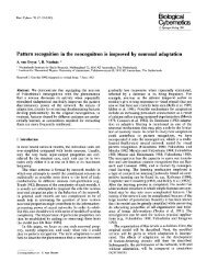
Section 4Denaturing Gel Electrophoresis (<strong>DGGE</strong>, CDGE, TTGE)4.1 Introduction to Denaturing Gradient Gel Electrophoresis (<strong>DGGE</strong>)Denaturing Gradient Gel Electrophoresis (<strong>DGGE</strong>) is an electrophoretic method to identifysingle base changes in a segment of DNA. Separation techniques on which <strong>DGGE</strong> is basedwere first described by Fischer and Lerman. 2 In a denaturing gradient acrylamide gel,double-stranded DNA is subjected to an increasing denaturant environment and will melt indiscrete segments called "melting domains". The melting temperature (T m ) of these domains issequence-specific. When the T m of the lowest melting domain is reached, the DNA will becomepartially melted, creating branched molecules. Partial melting of the DNA reduces its mobilityin a polyacrylamide gel. Since the T m of a particular melting domain is sequence-specific, thepresence of a mutation will alter the melting profile of that DNA when compared to wild-type.DNA containing mutations will encounter mobility shifts at different positions in the gel than thewild-type. If the fragment completely denatures, then migration again becomes a function ofsize (Figure 4.1).Denaturant0%100%* Wild TypePartially melted"mutant" “mutant”Partially melted"wild “wild type” type"Single strandsElectrophoresis* MutantDouble strandFig. 4.1. An example of DNA melting properties in a perpendicular denaturing gradient gel. At alow concentration of denaturant, the DNA fragment remains double-stranded, but as the concentration ofdenaturant increases, the DNA fragment begins to melt. Then, at very high concentrations of denaturant,the DNA fragment can completely melt, creating two single strands.In <strong>DGGE</strong>, the denaturing environment is created by a combination of uniform temperature,typically between 50 and 65 °C and a linear denaturant gradient formed with urea andformamide. A solution of 100% chemical denaturant consists of 7 M urea and 40% formamide.The denaturing gradient may be formed perpendicular or parallel to the direction ofelectrophoresis. A perpendicular gradient gel, in which the gradient is perpendicular to theelectric field, typically uses a broad denaturing gradient range, such as 0–100% or 20–70%. 2In parallel <strong>DGGE</strong>, the denaturing gradient is parallel to the electric field, and the range ofdenaturant is narrowed to allow better separation of fragments. 9 Examples of perpendicularand parallel denaturing gradient gels with homoduplex and heteroduplex fragments are shownin Figure 4.2.11
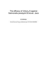
0%70%40%65%ABFig. 4.2. A. Perpendicular denaturing gradient gel in which the denaturing gradient is perpendicularto the electrophoresis direction. Mutant and wild-type alleles of exon 6 from the TP53 gene amplified fromprimary breast carcinomas and separated by perpendicular <strong>DGGE</strong> (0–70% denaturant) run at 80 V for 2 hoursat 56 °C. The first two bands on the left are heteroduplexes and the other two bands are the homoduplexes.B. Parallel denaturing gradient gel in which the denaturing gradient is parallel to the electrophoresisdirection. Mutant and wild-type alleles of exon 8 from the p53 gene separated by an 8% acrylamide:bis (37.5:1)gel with a parallel gradient of 40–65% denaturant. The gel was run at 150 V for 2.5 hours at 60 °C in 1x TAE buffer.Lane 1 contains the mutant fragment, lane 2 contains the wild-type fragment, lane 3 contains both the mutantand wild-type fragments.When running a denaturing gradient gel, both the mutant and wild-type DNA fragmentsare run on the same gel. This way, mutations are detected by differential migration of mutant andwild-type DNA. The mutant and wild-type fragments are typically amplified by the polymerasechain reaction (PCR) to make enough DNA to load on the gel. Optimal resolution is attainedwhen the molecules do not completely denature and the region screened is in the lowest meltingdomain. The addition of a 30–40 base pair GC clamp to one of the PCR primers insures that theregion screened is in the lower melting domain and that the DNA will remain partiallydouble-stranded. 34 An alternative to GC clamps is using psoralen derivative PCR primers calledChemiClamp primers. 10 Because ChemiClamps covalently link the two DNA strands at oneend, they should not be used when isolating a DNA fragment which is going to be sequencedfrom a gel. The size of the DNA fragments run on a denaturing gel can be as large as 1 kb inlength, but only the lower melting domains will be available for mutation analysis. For completeanalysis of fragments over 1 kb in length, more than one PCR reaction should be performed. 11The thermodynamics of the transition of double-stranded to single-stranded DNA havebeen described by a computer program developed by Lerman. 12 Bio-Rad offers a Macintosh ®computer program, MacMelt software, which calculates and graphs theoretical DNA meltingprofiles. Melting profile programs can show regions of theoretical high and low melting domainsof a known sequence. Placement of primers and GC clamps can be optimized by analysis ofplacement effect on the DNA melting profile.The method of creating heteroduplex molecules helps in detecting homoduplex mutations.This process is typically done when it is not originally possible to resolve a homoduplexmutation. Analysis of heteroduplex molecules can, therefore, increase the sensitivity of <strong>DGGE</strong>.Heteroduplexes can be formed by adding the wild-type and mutant template DNAs in the samePCR reaction or by adding separate PCR products together, then denaturing andallowing them to re-anneal. A heteroduplex has a mismatch in the double-strand causing adistortion in its usual conformation; this has a destabilizing effect and causes the DNA strandsto denature at a lower concentration of denaturant (Figure 4.3). The heteroduplex bands alwaysmigrate more slowly than the corresponding homoduplex bands under specific conditions.12
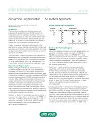
Wild-Type DNAMutant DNADenature and reannealHomoduplexDNAHeteroduplexDNA20%wtmutwt + mutDenaturantHeteroduplexesHomoduplexes60%Fig. 4.3. An example of wild-type and mutant DNA fragments that were denatured and re-annealedto generate four fragments: two heteroduplexes and two homoduplexes run on a paralleldenaturing gradient gel. The melting behavior of the heteroduplexes is altered so that they melt at a lowerdenaturant concentration than the homoduplexes and can be visualized on a denaturing gradient gel.Reagent PreparationThe concentration of denaturant to use varies for the sample being analyzed with theDCode system. Typically a broad denaturing gradient range is used, such as 0–100% or20–70%. The concentration of acrylamide can also vary, depending on the size of the fragmentanalyzed. Both 0% and 100% denaturant should be made as stock solutions. A 100% denaturantis a mixture of 7 M urea and 40% deionized formamide. Reagents for casting and runninga <strong>DGGE</strong> gel are included in the DCode Electrophoresis Reagent Kit for <strong>DGGE</strong>/CDGE,catalog number 170-9032.For different percent crosslinking, use the equation below to determine the amount ofBis to add. The example stock solution below is for an acrylamide/bis ratio of 37.5:1.40% Acrylamide/Bis (37.5:1)ReagentAmountAcrylamide38.93 gBis-acrylamide1.07 gdH 2Oto 100.0 mlFilter through a 0.45 µ filter and store at 4 °C.13
Polyacrylamide gels are described by reference to two characteristics:1) The total monomer concentration (%T)2) The crosslinking monomer concentration (%C)%T =%C =gm acrylamide + gm bis-acrylamideTotal Volumegm bis-acrylamidegm acrylamide + gm bis-acrylamidex 100x 10050x TAE BufferReagent Amount Final ConcentrationTris base 242.0 g 2 MAcetic acid, glacial 57.1 ml 1 M0.5 M EDTA, pH 8.0 100.0 ml 50 mMdH 2Oto 1,000.0 mlMix. Autoclave for 20–30 minutes. Store at room temperature.The table below provides the percentage acrylamide/bis needed for a particular size range.Gel PercentageBase Pair Separation6% 300–1000 bp8% 200–400 bp10% 100–300 bp0% Denaturing Solution6% Gel 8% Gel 10% Gel 12% Gel40% Acrylamide/Bis 15 ml 20 ml 25 ml 30 ml50x TAE buffer 2 ml 2 ml 2 ml 2 mldH 2O 83 ml 78 ml 73 ml 68 mlTotal volume 100 ml 100 ml 100 ml 100 mlDegas for 10–15 minutes. Filter through a 0.45 µ filter. Store at 4 °C in a brown bottle forapproximately 1 month.100% Denaturing Solution6% Gel 8% Gel 10% Gel 12% Gel40% Acrylamide/Bis 15 ml 20 ml 25 ml 30 ml50x TAE buffer 2 ml 2 ml 2 ml 2 mlFormamide (deionized) 40 ml 40 ml 40 ml 40 mlUrea 42 g 42 g 42 g 42 gdH 2O to 100 ml to 100 ml to 100 ml to 100 mlDegas for 10–15 minutes. Filter through a 0.45 µ filter. Store at 4 °C in a brown bottle forapproximately 1 month. A 100% denaturant solution requires re-dissolving after storage. Placethe bottle in a warm bath and stir for faster results.14
For denaturing solutions less than 100%, use the volumes for acrylamide, TAE and waterdescribed above in the 100% Denaturing Solution. Use the amounts indicated below for ureaand formamide.Denaturing Solution 10% 20% 30% 40% 50% 60% 70% 80% 90%Formamide (ml) 4 8 12 16 20 24 28 32 36Urea (g) 4.2 8.4 12.6 16.8 21 25.2 29.4 33.6 37.810% Ammonium PersulfateReagentAmountAmmonium persulfate0.1 gdH 2O1.0 mlStore at -20 °C for about a week.DCode Dye SolutionReagent Amount Final ConcentrationBromophenol blue 0.05 g 0.5%Xylene cyanol 0.05 g 0.5%1x TAE buffer 10.0 ml 1xStore at room temperature. This reagent is supplied in the DCode electrophoresis reagent kitfor <strong>DGGE</strong>, CDGE.2x Gel Loading DyeReagent Amount Final Concentration2% Bromophenol blue 0.25 ml 0.05%2% Xylene cyanol 0.25 ml 0.05%100% Glycerol 7.0 ml 70%dH 2O2.5 mlTotal volume10.0 mlStore at room temperature.1x TAE Running BufferReagentAmount50x TAE buffer140 mldH 2O6,860 mlTotal volume7,000 mlGel VolumesLinear Denaturing Gradient GelsThe table below provides the required gradient delivery system setting per gel size desired.The volume per syringe is for the amount required for each low and high density syringe, andthe volume adjustment setting sets the gradient delivery system for the proper delivery of solutions.The 7.5 x 10 cm and 16 x 16 cm size gels are recommended for the perpendicular gel formats,whereas the 16 x 10 cm and 16 x 16 cm gel formats are recommended for paralleldenaturing gels. The volume per syringe requires a larger volume of reagent than the volumesetting indicates, because the excess volume in the syringe is needed to push the correct amountof gel solution into the gel sandwich.15
Volume VolumeperAdjustmentSpacer Size Gel Size Syringe Setting0.75 mm 7.5 x 10 cm 5 ml 3.516 x 10 cm 8 ml 6.516 x 16 cm 11 ml 9.51.00 mm 7.5 x 10 cm 6 ml 4.516 x 10 cm 11 ml 9.516 x 16 cm 16 ml 14.51.50 mm 7.5 x 10 cm 8 ml 6.516 x 10 cm 15 ml 13.516 x 16 cm 24 ml 22.5Spacer Thickness 16 x 16 cm Gel 16 x 10 cm Gel0.75 mm 25 ml 15 ml1.00 mm 30 ml 20 ml1.50 mm 45 ml 26 mlSample Preparation1. It is important to optimize the PCR reaction to minimize unwanted products which mayinterfere with gel analysis. PCR products should be evaluated for purity by agarose gelelectrophoresis before being loaded onto a denaturing acrylamide gel.2. For a perpendicular denaturing gel, load about 1–3 µg of amplified DNA per well(usually 50% of a 100 µl PCR volume from a 100 ng DNA template). Both wild-typeand mutant samples are mixed together and run on the same gel.3. For a parallel denaturing gel, load 180–300 ng of amplified DNA per well (usually 5–10%of a 100 µl PCR volume from a 100 ng DNA template). A wild-type control should be runon every gel.4. Add an equal volume of 2x gel loading dye to the sample.5. Heteroduplexes can be generated during PCR by amplifying the mutant and wild-type samplesin the same tube. If the samples are amplified in separate tubes, then heteroduplexes can beformed by mixing an equal amount of mutant and wild-type samples in one tube. Heat the tubeat 95 °C for 5 minutes, then place at 65 °C for 1 hour, and let slowly cool to room temperature.Temperature ControllerThe temperature controller maintains the desired buffer temperature in the DCode system(Figure 4.4). The actual and set buffer temperatures are displayed in °C. The set temperatureand the temperature ramp rate (RR) can be adjusted by using the raise and lower buttons. The°C/RR button is used to scroll between the two parameters.ACTUALHEATERSET°CRR60.060.0°CFig. 4.4. The temperature controller displays the actual temperature, set temperature, andtemperature ramp rate.16
Pre-heating the Running Buffer1. Fill the electrophoresis tank with 7 L of 1x TAE running buffer.Note: It is recommended that the running buffer not be reused. Reusing the running buffermay affect the migration rate and band resolution.2. Place the temperature control module on top of the electrophoresis tank. Attach the powercord to the temperature control module and turn the power, pump, and heater on. Theclear loading lid should be on the temperature control module during preheating.3. Set the temperature controller to the desired temperature. Set the temperature ramp rateto 200 °C/hr to allow the buffer to reach the desired temperature the quickest.4. Preheat the buffer to the set temperature. It can take 1 to 1.5 hours for the system to heatthe buffer up to the set temperature. Heating the buffer in a microwave helps reduce thepreheating time.Assembling the Perpendicular Gradient Gel SandwichFor perpendicular gel formats, 7.5 x 10 cm (dual) and 16 x 16 cm (single) gel sandwich sizesare recommended. These two different perpendicular gel formats consist of a set of spacers thatprovide casting at the side of the gel sandwich via the stopcock. To insure proper alignment,make sure all plates and spacers are clean and dry before assembly. Use caution when assemblingthe glass plate sandwiches. Wear gloves and eye protection at all times.1. Assemble the gel sandwich on a clean surface. Lay the large rectangular plate down first,then place the left and right spacers of equal thickness along the short edges of the largerrectangular plate. To assemble perpendicular gradient gels, place the spacers so that theholes on the spacers are at the top of the plate with the grooved side of the spacer againstthe larger glass plate. When properly placed, the notched edges of the spacers will faceeach another.2. Place a short glass plate on top of the spacers so that it is flush with the bottom edge ofthe long plate.3. Loosen the single screw of each sandwich clamp by turning counterclockwise. Place eachclamp by the appropriate side of the gel sandwich with the locating arrows facing up andtoward the glass plates (Figure 4.5).Fig. 4.5. Positioning glass plates, spacers, and clamps.17
4. Grasp the gel sandwich firmly. Guide the left and right clamps onto the sandwich sothat the long and short plates fit the appropriate notches in the clamp (Figure 4.6). Tightenthe screws enough to hold the plates in place.Fig. 4.6. Attaching the clamps to the glass plate assembly.5. Place the sandwich assembly in the alignment slot (the slot without cams) of the castingstand with the short glass plate forward (Figure 4.7). Loosen the sandwich clamps andinsert an alignment card to keep the spacers parallel to the clamps.Note: Always use the alignment slot and alignment card to set the spacers in place. Failureto use these can result in gel leakage when casting, as well as buffer leakage during the run.Fig. 4.7. Aligning spacers in the sandwich assembly.18
6. Align the plates and spacers by simultaneously pushing inward on both clamps at thelocating arrows while, at the same time, pushing down on the spacers with your thumbs.Tighten both clamps just enough to hold the sandwich in place. Pushing inward on bothclamps at the locating arrows will insure that the spacers and glass plates are flush againstthe sides of the clamps (Figure 4.7).7. Remove the alignment card. Then, remove the sandwich assembly from the casting standand check that the plates and spacers are flush at the bottom. If they are not flush, realignthe sandwich and spacers (Repeat steps 5–7).8. When a good alignment and seal are obtained, tighten the clamp screws until it is finger-tight.9. Place the proper comb in the sandwich and align it against the notches in the spacers. Forthe 7.5 x 10 cm perpendicular gradient gel, insert the middle spacer into the center of thesandwich until it fits into the middle notch on the comb. Straighten the spacer and the comb.The bottom of the middle spacer should also be flush against the glass plates (Figure 4.8).Note: The proper comb for a 7.5 x 10 cm gel is the dual comb that requires a middlespacer to separate the two 7.5 x 10 cm gels, whereas the 16 x 16 cm gel comb is a singlecomb that does not require a middle spacer.Fig. 4.8. Positioning the middle spacer in a 7.5 x 10 cm gel sandwich assembly.10. Inspect the comb gasket to insure that the comb gasket is free of gel material. Remove anypolymerized material in the comb gasket vent ports. The soft comb gasket should lay flatwithin the comb gasket holder.Note: To remove the soft comb gasket from the holder, push the gasket away from the fourholes in the holder. To replace the comb gasket, insert the gasket into the holder with thethick portion in first. Place one corner of the gasket against the top portion of the holder.With a flat spatula, guide the four tabs into the four holes. Carefully run the spatula acrossthe gasket to completely set the gasket in place.19
11. Stand the sandwich assembly upright on a flat surface. Loosen the comb gasket holder screwsuntil the threads can no longer be seen. Mark an arrow on the middle of the screw head usinga permanent marker (this will be the marker for adjusting the proper screw tension). With thecomb gasket screws and the long plate facing you, slide the comb gasket holder down overthe top of the assembled glass sandwich. When the comb gasket is properly placed, the angledcuts on the edges of the comb gasket will rest on the complementary angled cuts at the topof each spacer. Turn the screws until they just make contact with the glass plate, then twistthe screws an additional 1/4 turn.12. Before the screws can be completely tightened, the pressure clamp must be attached to thesandwich assembly. Loosen the pressure clamp screw. Mark an arrow on the middle of thescrew head using a permanent marker (this will be the marker for adjusting the proper screwtension). Lay the pressure clamp on a flat surface so that the notched cut-out faces the ceilingand the pressure clamp screw points up and away from you.13. Without touching the comb gasket holder, turn the assembled glass sandwich so that the combgasket screws are facing down and the vent ports are facing up. Center the assembly over thepressure clamp and allow the assembly to rest on top of it. A properly placed pressure clampwill be situated on the middle of the sandwich with the notched cut-out against the bottom ofthe glass plate. Proper placement of the sandwich assembly in the pressure clamp will insurethat equal force is applied to the comb gasket holder during the final tightening of the screws.Twist the pressure clamp screw until it makes contact with the comb gasket holder, thentighten the pressure clamp screw two additional turns (use the arrow to keep track of the turns).Note: Check to insure that the bottom of the glass plates are still flush. If the plates are offset,one or both of the sandwich clamps may not be tightened. Repeat steps 5–13.14. Tighten the comb gasket screws an additional one turn. If it is tightened more, theglass plates may crack. For a proper seal, check to see that the notches on both thecomb gasket and spacers are sealed against each other. It is important that the gasketis placed properly to prevent leakage while casting. Remove the pressure clamp.15. Twist the injection port fitting into the holes on the sandwich clamps. Do not over-tighten;it will damage the O-ring and cause leakage. A snug fit is all that is needed to place theinjection port against the glass plate assembly. Push a stopcock into each of the injection portfittings. Make sure that the fit is snug. A loose stopcock may cause leakage during casting.16. Place the gray sponge onto the front casting slot. The camshafts on the casting stand shouldhave the handles pointing up and pulled out. Place the sandwich on the sponge with the shorterplate facing forward. When the sandwich is placed correctly, press down on the sandwichand turn the handles of the camshaft down so that the cams lock the sandwich in place.a. For a 7.5 x 10 cm dual gel sandwich, only half of the sandwich is cast at a time. Openthe stopcock and unplug the vent port on the side of the sandwich where the gel isbeing cast. To prevent leakage the other half of the sandwich should have a closedstopcock and plugged vent port.b. For a 16 x 16 cm gel sandwich, both vent ports should be plugged to prevent leakageduring casting. The 16 x 16 cm spacers are one orientation only, thus the special castinggroove is always on the right-hand side and the smaller, shorter groove on the left-handside of the gel sandwich.17. Tilt the gel sandwich assembly and casting stand using the tilt rod as a leg. Adjust the tiltlevel to the highest etched line on the rod (the one farthest from the black tilt-rod cap) forthe 7.5 x 10 cm format and the lowest etched line on the rod for the 16 x 16 cm format.18. Familiarize yourself with the Model 475 Gradient Delivery <strong>System</strong> before castingperpendicular gradient gels.20
Casting Perpendicular Denaturing Gradient Gels1. One length of Tygon tubing is provided and should be cut into two 15.5 cm lengths andone 9 cm length. The longer pieces of Tygon tubing will be used to conduct the gel solutionfrom the syringes into the Y-fitting. The short piece of Tygon tubing will conduct thegel solution from the Y-fitting to the gel sandwich. Connect one end of the 9 cm Tygontubing to the Y-fitting and connect a luer coupling to the other end of the 9 cm tubing.Connect luer fittings onto the two long pieces of tubing. Connect the luer fittings to 10 mlor 30 ml syringes. Do not connect the long Tygon tubing to the Y-fitting at this time.2. Label one of the syringes LO (for the low density solution) and one HI (for the high densitysolution). Attach a plunger cap onto each syringe plunger “head.” Position the plunger"head" in the middle of the plunger cap and tighten enough to hold the plunger in place.Position the cap in the middle for proper alignment with the lever on the gradient deliverysystem. Slide each syringe into a syringe sleeve. Move the sleeve to the middle ofthe syringe, keeping the volume gradations visible. Make sure that the lever attachmentscrew is in the same plane as the flat or back side of the sleeve. This is very important forproper attachment of the syringe to the lever.Note: Insure that the tubing is free of any gel material by pushing water through the tubing withthe syringe. The tubing should be free of material before casting, remove any remaining waterfrom the tubing.3. Rotate the cam wheel counterclockwise to the vertical or start position. To set the desireddelivery volume, loosen the volume adjustment screw. Place the volume setting indicatorlocated on the syringe holder to the desired volume setting. Tighten the volume adjustmentscrew. For 7.5 x 10 cm gels (1 mm thick), set the volume setting indicator to 4.5. For16 x 16 cm gels (1 mm thick), set the volume setting indicator to 14.5. Refer to Section 4.1.4. From the stocks solutions, pipet out the desired amounts of the high and low density gel solutionsinto two disposable test tubes, Section 4.1.Optional: To visually check the formation of the gradient, add 100 µl of DCode dyesolution per 5 ml high density solution.Note: The gel solution volume should be greater than the amount set on the volumeadjustment lever. For example, if the setting indicator is set at 4.5, the syringe shouldcontain 5 ml of the gel solution. This extra solution is needed to push the correct amountinto the gel sandwich.The steps below are time-sensitive (about 7–10 minutes). Insure that steps 1 through 4are done before proceeding further. Be thoroughly familiar with the following stepsbefore casting the gel.5. Add a final concentration of 0.09% (v/v) each of ammonium persulfate and TEMEDsolutions. The 0.09% (v/v) concentrations allow about 5–7 minutes to finish casting the gelbefore polymerization. Cap and mix by inverting several times. With the syringe connectedto the tubing, withdraw all of the high density solution into the HI syringe. Do the samefor the low density solution into the LO syringe.Note: Acrylamide is a very hazardous substance. Use caution: wear gloves and eye protectionat all times. Avoid skin contact.6. Carefully remove air bubbles from the LO syringe by turning it upside down (plungercap towards the bench) and gently tapping. Push the gel solution to the end of the tubing.Do not push it out of the tubing as loss of gel solution will disturb the volume required tocast the desired gel.21
7. Place the LO syringe into the gradient delivery system syringe holder (LO density side)by holding the syringe by the plunger and inserting the lever attachment screw into thelever groove. Do not handle the syringe. It will dispense the gel solution out of the syringe.Casting a perpendicular gel is referred to as a bottom filling method, so place the LOsyringe on the correct side of the gradient system.8. Carefully remove the air bubbles from the HI syringe by turning it upside down (plungercap towards the bench) and gently tapping. Push the gel solution to the end of the tubing.Do not push it out of the tubing as loss of gel solution will disturb the volume required tocast the desired gel.9. Place the HI syringe into the gradient delivery system syringe holder (HI density side) byholding the syringe by the plunger and inserting the lever attachment screw into the levergroove. Do not handle the syringe. It will dispense the gel solution out of the syringe.10. Slide the tubing from the low density syringe to one end of the Y-fitting. Do the same forthe high density syringe.11. Connect the 9 cm tubing with the luer coupling on the sandwich assembly stopcock. Insurethat the stopcock is open and that the vent port is unplugged for the half of the sandwichbeing cast.Note: For a 16 x 16 cm single gel, both stopcocks are open during casting. After casting, bothstopcocks are closed.12. Rotate the cam wheel slowly and steadily to deliver the gel solution. It is important to cast thegel solution at a steady pace to avoid disturbances between gel solutions within the sandwich.Fig. 4.9. Casting a perpendicular gradient gel using the Model 475 gradient delivery system.13. Plug the vent port and close the stopcock on the gel sandwich when the cam wheel hasreached the stop position. Carefully level the gel sandwich by adjusting the gasket tiltrod. Be sure to loosen the tilt rod screw and not the sandwich clamp screw.Note: For a properly cast perpendicular gradient gel it is extremely important to level thesandwich assembly after casting.22
14. Immediately remove the tubing from the sandwich assembly stopcock. Place the tubinginto a beaker of water and reverse the cam on the Gradient Delivery <strong>System</strong>. This will rinsethe tubing and Y-fitting. Remove both syringes from the syringe holder on the gradientdelivery system. Detach the syringe tubing from the Y-fitting. Run or push water out throughthe syringe, tubing and Y-fitting several times to get rid of any residual gel solution. It isextremely important that this is done quickly after casting to avoid any gel polymerization.15. Let the gel polymerize for about 60 minutes. To cast the other half of the 7.5 x 10 cm gelformat, remove the gasket tilt rod and place it on the other side of the comb gasket. Repeatsteps 4 through 15.Note: If casting a single 7.5 x 10 cm gel, let the gel solution polymerize for 60 minutes.Carefully remove the comb gasket; leave the comb in place and pipette (on an opening nearthe spacer) a 10 ml gel solution plus initiators in the uncast half of the sandwich to create a dam.16. After polymerization, remove the comb by pulling it straight up slowly and gently.17. Continue with Section 8 for electrophoresis.Assembling the Parallel Gradient Gel SandwichFor parallel gel formats, a 16 x 16 cm gel sandwich size is recommended. The parallel gelformat does not require special casting grooves in the spacers, so the straight edge portion(ungrooved side) of the spacers is used. To insure proper alignment, make sure all plates andspacers are clean and dry before assembly. Use caution when assembling the glass plate sandwiches.Wear gloves and eye protection at all times.1. Assemble the gel sandwich on a clean surface. Lay the large rectangular plate down first, thenplace the left and right spacers of equal thickness along the short edges of the larger rectangularplate. To assemble parallel gradient gels, place the spacers so that the grooved opening of thespacers face the sandwich clamps. When properly placed, the grooved side of the spacers andthe notches will face the sandwich clamps, and the hole is located near the top of the plates.2. Place the short glass plate on top of the spacers so that it is flush with the bottom edge ofthe long plate.3. Loosen the single screw of each sandwich clamp by turning each screw counterclockwise.Place each clamp by the appropriate side of the gel sandwich with the locating arrowsfacing up and toward the glass plates (Figure 4.10).Fig. 4.10. Positioning glass plates, spacers, and clamps.23
4. Grasp the gel sandwich firmly. Guide the left and right clamps onto the sandwich so thatthe long and short plates fit the appropriate notches in the clamp. Tighten the screwsenough to hold the plates in place (Figure 4.11).Fig. 4.11. Attaching the clamps to the glass plate assembly.5. Place the sandwich assembly in the alignment slot (the slot without cams) of the castingstand with the short glass plate forward (Figure 4.12). Loosen the sandwich clamps andinsert an alignment card to keep the spacers parallel to the clamps.Note: Always use the alignment slot and alignment card to set the spacers in place. Failureto use these can result in gel leakage while casting, as well as buffer leakage during the run.6. Align the plates and spacers by simultaneously pushing inward on both clamps at thelocating arrows while at the same time pushing down on the spacers with your thumbs;tighten both clamps just enough to hold the sandwich in place. Pushing inward on bothclamps at the locating arrows will insure that the spacers and glass plates are flush againstthe sides of the clamps (Figure 4.12).Fig. 4.12. Aligning spacers in the sandwich assembly.24
7. Remove the alignment card. Remove the sandwich assembly from the casting stand andcheck that the plates and spacers are flush at the bottom. If the spacers and glass plates arenot flush, realign the sandwich and spacers to obtain a good seal (Repeat steps 5–7).8. When a good alignment and seal are obtained, tighten the clamp screws until it is finger-tight.Casting Parallel Denaturing Gradient Gels1. Place the gray sponge onto the front casting slot. The camshafts on the casting stand shouldhave the handles pointing up and pulled out. Place the sandwich assembly on the sponge withthe shorter plate facing you. When the sandwich is placed correctly, press down on thesandwich and turn the handles of the camshaft down so that the cams lock the sandwich inplace. Position the gel sandwich assembly by standing it upright.2. One length of Tygon tubing is provided and should be cut into two 15.5 cm lengths andone 9 cm length. The longer pieces of Tygon tubing will be used to conduct the gelsolution from the syringes into the Y-fitting. The short piece of Tygon tubing will conductthe gel solution from the Y-fitting to the gel sandwich. Connect one end of the 9 cm Tygontubing to the Y-fitting and connect a luer coupling to the other end of the 9 cm tubing.Connect luer fittings onto the two long pieces of tubing. Connect the luer fittings to 30 mlsyringes. Do not connect the long Tygon tubing to the Y-fitting at this time.3. Label one of the syringes LO (for the low density solution) and one HI (for the high densitysolution). Attach a plunger cap onto each syringe plunger “head.” Position the plunger"head" in the middle of the plunger cap and tighten enough to hold the plunger in place.Position the cap in the middle for proper alignment with the lever on the gradient deliverysystem. Slide each syringe into a syringe sleeve. Move the sleeve to the middle ofthe syringe, keeping the volume gradations visible. Make sure that the lever attachmentscrew is in the same plane as the flat or back side of the sleeve. This is very important forproper attachment of the syringe to the lever.Note: Insure that the tubing is free of any gel material by pushing water through the tubingwith the syringe. The tubing should be free of material before casting, remove anyremaining water from the tubing.4. Rotate the cam wheel counterclockwise to the vertical or start position. To set the desireddelivery volume, loosen the volume adjustment screw. Place the volume setting indicatorlocated on the syringe holder to the desired volume setting. Tighten the volume adjustmentscrew. For 16 x 16 cm gels (1 mm thick), set the volume setting indicator to 14.5. Refer toSection 4.1.5. From the stocks solutions, pipet out the desired amounts of the high and low density gelsolutions into two disposable test tubes (refer to the Section 4.1).Optional: To visually check the formation of the gradient, add 100 µl of DCode dyesolution per 5 ml high density solution.The steps below are time-sensitive (about 7–10 minutes). Insure that steps 2 through5 are done before proceeding further. Be thoroughly familiar with the followingsteps before casting the gel.6. Add the final concentration of 0.09% (v/v) each of ammonium persulfate and TEMEDsolutions. The 0.09% (v/v) concentrations allow about 5–7 minutes to finish casting the gelbefore polymerization. Cap and mix by inverting several times. With the syringe connectedto the tubing, withdraw all of the high density solution into the HI syringe. Do the same forthe low density solution into the LO syringe.Note: Acrylamide is a very hazardous substance. Use caution: wear gloves and eye protectionat all times. Avoid skin contact.25
7. Carefully remove air bubbles from the LO syringe by turning the syringe upside down(plunger cap towards the bench) and gently tapping the syringe. Push the gel solution tothe end of the tubing. Do not push it out of the tubing as loss of solution will disturb thevolume required to cast the desired gel.Note: The gel solution volume should be greater than the amount set on the volume adjustmentlever. For example, if the indicator setting is set at 14.5, the syringe should contain15 ml of solution. This extra solution is needed to deliver the correct amount for casting.8. Place the LO syringe into the gradient delivery system syringe holder (LO density side) byholding the syringe by the plunger and inserting the lever attachment screw into the levergroove. Do not handle the syringe. It will dispense the gel solution out of the syringe.Casting a parallel gel is referred to as a top filling method, so place the LO syringe onthe correct side of the gradient system.9. Carefully remove the air bubbles from the HI syringe by turning the syringe upside down(plunger cap towards the bench) and gently tapping the syringe. Push the solution to theend of the tubing. Do not push it out of the tubing as loss of solution will disturb the volumerequired to cast the desired gel.10. Place the HI syringe into the gradient delivery system syringe holder (HI density side) byholding the syringe by the plunger and inserting the lever attachment screw into the lever.Do not handle the syringe. It will dispense the gel solution out of the syringe.11. Slide the tubing from the low density syringe over one end on the Y-fitting. Do the samefor the high density syringe.12. Attach a 19 gauge needle to the coupling. Hold the beveled side of the needle at thetop-center of the gel sandwich and cast (Figure 4.13). For convenience, the needle can betaped in place.Fig. 4.13. Casting a parallel gradient gel.13. Rotate the cam wheel slowly and steadily to deliver the gel solution. It is important tocast the gel solution at a steady pace to avoid any disturbances between the gel solutionswithin the gel sandwich.14. Carefully insert the comb to the desired well depth and straighten. Let the gel polymerizefor about 60 minutes.26
15. Place the tubing and needle into a beaker of water and reverse the cam on the GradientDelivery <strong>System</strong>. This will rinse the tubing and Y-fitting. Remove both syringes from thesyringe holder on the gradient delivery system. Detach the syringe tubing from the Y-fitting.Run or push water out through the syringe, tubing, and Y-fitting several times to get rid ofany residual gel solution. It is very important that this is done quickly after casting to avoidpremature gel polymerization.16. After polymerization, remove the comb by pulling it straight up slowly and gently.17. Continue with Section 8 for electrophoresis.4.2 Introduction to Constant Denaturing Gel Electrophoresis (CDGE)Constant Denaturing Gel Electrophoresis is a modification of <strong>DGGE</strong>. In CDGE, thedenaturant concentration that gives optimal resolution from a parallel or perpendicular <strong>DGGE</strong>gel is held constant. 13 The optimal concentration of denaturant to use for a CDGE is determinedfrom the maximum split between wild-type and mutant DNA, as seen in the perpendicular orparallel denaturing gel. To calculate the concentration of denaturant for a CDGE gel, firstplace a fluorescent ruler along the axis of the denaturant gradient when taking a photograph.Then, determine the distance along the gradient where the maximum split is seen betweenbands. In the example in Figure 4.14, the distance is 5 cm. Divide this distance by the lengthof the gel and multiply by the denaturant range. For example, (5 ÷ 8) x 50% = 31 %. Addthis number to the starting denaturant concentration to determine the optimum concentrationto use for CDGE (20% + 31% = 51%). The same calculation can be applied to samples thatare run on a parallel <strong>DGGE</strong> gel.After a mutation has been identified by previous <strong>DGGE</strong> gels, a CDGE gel can be used torapidly screen samples for the presence of a mutation. With no gradient required, rapid, highthroughputscreening is possible. As in <strong>DGGE</strong>, the formation of heteroduplex analysis can helpin resolving wild-type and mutated fragments when it is not possible to detect a mutation byrunning homoduplex fragments. An example of a CDGE gel is shown in Figure 4.15.20% 70%Fig. 4.14. Example of perpendicular <strong>DGGE</strong> gel used for determining the optimum denaturantconcentration used in a CDGE gel. The distance along the gradient where the maximum split seen betweensamples is 5 cm. The denaturant concentration of the gradient at this distance is 51%. Therefore, the CDGEgel should use a denaturant concentration of 51%.27
1 2 3Fig. 4.15. Constant denaturing gel. Amplified mutant and wild-type alleles of exon 8 from the p53gene. Separation by CDGE run at 130 V for 2.5 hours on a 10% acrylamide gel in 51% denaturant at56 °C. Lane 1, mutant allele; lane 2, wild-type allele; lane 3, mutant and wild-type allele.Reagent PreparationThe concentration of denaturant is determined from a perpendicular or parallel <strong>DGGE</strong>gel. The concentration of acrylamide may vary, depending on the size of the fragment that isbeing analyzed. Both 0% and 100% denaturant should be made as stock solutions. A 100%denaturant is a mixture of 7 M urea and 40% deionized formamide. Reagents for casting andrunning CDGE gels are included in the DCode electrophoresis reagent kit for <strong>DGGE</strong>/CDGE,catalog number 170-9032.For different percent crosslinking, use the equation below to determine the amount ofBis to add. The example stock solution below is for an acrylamide/bis ratio of 37.5:1.40% Acrylamide/Bis (37.5:1)ReagentAmountAcrylamide38.93 gBis-acrylamide1.07 gdH 2Oto 100.0 mlFilter through a 0.45 µ filter and store at 4 °C.For different percent crosslinking, use the equation below to determine the amount ofBis to add. The example stock solution is for an acrylamide/bis ratio of 37.5:1.Polyacrylamide gels are described by reference to two characteristics:1) Total monomer concentration (%T)2) Crosslinking monomer concentration (%C)%T =%C =gm acrylamide + g bis-acrylamide x 100total volumegm bis-acrylamidegm acrylamide + g bis-acrylamidex 10028
50x TAE BufferReagent Amount Final ConcentrationTris base 242.0 g 2 MAcetic acid, glacial 57.1 ml 1 M0.5 M EDTA, pH 8.0 100.0 ml 50 mMdH 2Oto 1,000.0 mlMix. Autoclave for 20–30 minutes. Store at room temperature.0% DenaturingSolution 6% Gel 8% Gel 10% Gel 12% Gel40% Acrylamide/Bis 15 ml 20 ml 25 ml 30 ml50x TAE buffer 2 ml 2 ml 2 ml 2 mldH 2O 83 ml 78 ml 73 ml 68 mlTotal volume 100 ml 100 ml 100 ml 100 mlDegas for about 10–15 minutes. Store at 4 °C in a brown bottle for approximately 1 month.100% DenaturingSolution 6% Gel 8% Gel 10% Gel 12% Gel40% Acrylamide/Bis 15 ml 20 ml 25 ml 30 ml50x TAE buffer 2 ml 2 ml 2 ml 2 mlFormamide (deionized) 40 ml 40 ml 40 ml 40 mlUrea 42 g 42 g 42 g 42 gdH 2O to 100 ml to 100 ml to 100 ml to 100 mlDegas for about 10–15 minutes. Store at 4 °C in a brown bottle for approximately 1 month.A 100% denaturant solution requires re-dissolving after storage. Place the bottle in a warmbath and stir for faster results.To cast constant denaturing gradient gels, use the formula below to determine the volume of0% and 100% denaturing solutions needed to achieve the desired denaturant concentration.1. (% desired denaturant) (total gel volume needed) = ml of 100% denaturant solution2. (total gel volume needed) - (ml of 100% denaturant) = ml of 0% denaturant solutionExample: To cast a 52% constant denaturing gel, use 30 ml total volume for a 16 x 16 cmgel with a 1.0 mm spacer.1. (0.52)(30 ml) = 15.6 ml of 100% denaturing solution needed2. (30 ml) - (15.6 ml) = 14.4 ml of 0% denaturing solution neededThe table below provides the percentage acrylamide/bis needed for a particular size range.Gel PercentageBase Pair Separation6% 300–1,000 bp8% 200–400 bp10% 100–300 bp10% Ammonium PersulfateReagentAmmonium persulfatedH 2OStore at -20 °C for about a week.Amount0.1 g1.0 ml29
DCode Dye SolutionReagent Amount Final ConcentrationBromophenol blue 0.05 g 0.5%Xylene cyanol 0.05 g 0.5%1x TAE buffer 10.0 ml 1xStore at room temperature.2x Gel Loading DyeReagent Amount Final Concentration2% Bromophenol blue 0.25 ml 0.05%2% Xylene cyanol 0.25 ml 0.05%100% Glycerol 7.0 ml 70%dH 2O2.5 mlTotal volume10.0 mlStore at room temperature.1x TAE Running BufferReagent50x TAE bufferdH 2OTotal volumeAmount140 ml6,860 ml7,000 mlGel VolumesThe table below provides the required volume per gel size and spacer thickness.Spacer Thickness 16 x 16 cm Gel 16 x 10 cm Gel0.75 mm 25 ml 15 ml1.00 mm 30 ml 20 ml1.50 mm 45 ml 26 mlSample Preparation1. It is important to optimize the PCR reaction to minimize unwanted products which mayinterfere with gel analysis. The PCR products should be evaluated for purity by agarosegel electrophoresis before being loaded onto a denaturing acrylamide gel.2. For a constant denaturing gel, load about 180–300 ng of amplified DNA per well (usually5–10% of a 100 µl PCR volume from a 100 ng DNA template). A wild-type controlshould be run on every gel.3. Add an equal volume of 2x gel loading dye to the sample.4. Heteroduplexes can be generated during PCR by amplifying the mutant and wild-typesamples in the same tube. If the samples are amplified in separate tubes, then heteroduplexescan be formed by mixing an equal amount of mutant and wild-type samples inone tube. Heat the tube at 95 °C for 5 minutes, then place at 65 °C for 1 hour, and letslowly cool to room temperature.30
Temperature ControllerThe temperature controller maintains the desired buffer temperature in the DCode system(Figure 4.16). The actual and set buffer temperatures are displayed in °C. The set temperatureand the temperature ramp rate (RR) can be adjusted by using the raise and lower buttons. The°C/RR button is used to scroll between the two parameters.ACTUALHEATERSET°CRR60.060.0°CFig. 4.16. The temperature controller displays the actual temperature, set temperature, andtemperature ramp rate.Pre-heating the Running Buffer1. Fill the electrophoresis tank to the “Fill” line with 7 L of 1x TAE buffer.Note: It is recommended that the running buffer not be reused. Reusing the running buffermay affect the migration rate and band resolution.2. Place the temperature control module on top of the chamber. Attach the power cord to thetemperature control module and turn the power and heater switch on. The clear loadinglid should be on the temperature control module during preheating.3. Set the temperature to the desired temperature. Set the temperature ramp rate to 200 °C/hr.to allow the buffer to reach the desired temperature the quickest.4. Preheat the buffer to the set temperature. It can take 1 to 1.5 hours for the system to heatthe buffer up to the set temperature. Heating the buffer in a microwave helps reduce thepreheating time.Assembling the CDGE Gel SandwichFor constant denaturing gel formats, a 16 x 16 cm gel sandwich is recommended. To insureproper alignment, make sure all plates and spacers are clean and dry before assembly. Use cautionwhen assembling the glass plate sandwiches. Wear gloves and eye protection at all times.1. Assemble the gel sandwich on a clean surface. Lay the large rectangular plate down first,then place the left and right spacers of equal thickness along the short edges of thelarger rectangular plate.2. Place a short glass plate on top of the spacers so that it is flush with the bottom edge ofthe long plate.3. Loosen the single screw of each sandwich clamp by turning it counterclockwise. Placeeach clamp by the appropriate side of the gel sandwich with the locating arrows facing upand toward the glass plates (Figure 4.17).31
Fig. 4.17. Positioning glass plates, spacers, and clamps.4. Grasp the gel sandwich firmly. Guide the left and right clamps onto the sandwich so thatthe long and short plates fit the appropriate notches in the clamp (Figure 4.18). Tightenthe screws enough to hold the plates in place.Fig. 4.18. Attaching the clamps to the glass plate assembly.5. Place the sandwich assembly in the alignment slot (the slot without cams) of the castingstand with the short glass plate forward (Figure 4.19). Loosen the sandwich clamps andinsert an alignment card to keep the spacers parallel to the clamps.Note: Always use the alignment slot and alignment card to set the spacers in place. Failureto use these can result in gel leakage when casting, as well as buffer leakage during the run.32
6. Align the plates and spacers by simultaneously pushing inward on both clamps at the locatingarrows while pushing down on the spacers with your thumbs. Tighten both clamps just enoughto hold the sandwich in place. Pushing inward on both clamps at the locating arrows willinsure that the spacers and glass plates are flush against the sides of the clamps (Figure 4.19).Fig. 4.19. Aligning spacers in the sandwich assembly.7. Remove the alignment card. Remove the sandwich assembly from the casting stand andcheck that the plates and spacers are flush at the bottom. If they are not flush, realign thesandwich and spacers for a good seal (Repeat steps 5–7).8. When a good alignment and seal are obtained, tighten the clamp screws until it is finger-tight.Casting CDGE Gels1. Place the gray sponge onto the front casting slot. The camshafts on the casting stand shouldhave the handles pointing up and pulled out. Place the sandwich assembly (16 x 16 cm)on the sponge with the shorter plate facing forward. When the sandwich is placedcorrectly, press down on it and turn the handles of the camshaft down so that the camslock the sandwich in place.2. Into a 50 ml tube, add the required amounts of low density and high density solutionsrequired for the desired denaturant percentage (see CDGE calculation, Section 4.2). Adda final concentration of 0.09% (v/v) each of ammonium persulfate and TEMED solutions.Cap the tube and mix.3. Insert a comb in the gel sandwich and tilt it so the teeth are at a slight angle. This will preventair from being trapped under the comb teeth when pouring the gel solution (Figure 4.20).33
Fig. 4.20. Pouring a CDGE gel.4. Pour or pipette the gel solution into the sandwich until the gel solution covers the wellsof the comb. Straighten the comb to the desired well depth. Add more gel solution ifneeded.5. Allow the gel to polymerize for about 60 minutes. After polymerization, remove the combby pulling it straight up slowly and gently.6. Continue with Section 8 for electrophoresis.4.3 Introduction to Temporal Temperature Gradient GelElectrophoresis (TTGE)Temporal Temperature Gradient Gel Electrophoresis 14,15 (TTGE) exploits the principle onwhich <strong>DGGE</strong> is based, without requiring a chemical denaturing gradient. Amplified mutantand wild-type DNA from the gene of interest is loaded onto a polyacrylamide gel containing aconstant concentration of urea. During electrophoresis, the temperature is increased gradually anduniformly. The result is a linear temperature gradient over the length of the electrophoresis run.Thus, a denaturing environment is formed by the constant concentration of urea in the gel incombination with the temporal temperature gradient. With no chemical gradient required, rapid,high-throughput screening is possible.The DCode system allows precise control of the temperature ramp rate measured in °C perhour. Control over the temperature range and ramp rate allows optimum denaturing conditions.An example of a TTGE gel is shown in Figure 4.21.34
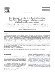
1 2 3 4 5Fig. 4.21. Temporal temperature gradient gel. Amplified mutant and wild-type alleles of exon 7 fromthe cystic fibrosis gene. Separation by TTGE run at 130 V for 5 hours in 1.25x TAE buffer on a 6 M urea/6%acrylamide gel (37.5:1) using a temperature range of 50–60 °C and a ramp rate of 2 °C/hr. Lane 1, mutantallele (1154 insTC); lane 2, mutant allele (G330X); lane 3, mutant allele (deltaF311); lane 4, mutant allele(R334W); and lane 5, wild-type allele. (Samples courtesy of L. Silverman, Division of Molecular Pathology,University of North Carolina School of Medicine)Calculating the Run ParametersTo determine the temperature range to use with TTGE, a melting profile of the DNAsequence should be generated using a DNA melting software program, such as Bio-Rad’sMacMelt software. As in <strong>DGGE</strong>, the addition of a 30–40 base pair GC clamp should be addedto one of the PCR primers to insure that the region screened is in the lowest melting domain. Thetemperature range for the gradient can be calculated from the melting profile graph by firstdetermining the lowest and highest non-GC clamp melting temperature of the DNA sequence(See example in Figure 4.22). From the calculated low and high temperatures, thetheoretical melting temperatures can be lowered by adding urea to the gel. A denaturing urea gelwill lower the theoretical melting temperature of DNA by 2 °C for every mole of urea. 32, 33In Figure 4.22, the theoretical melting temperature range on the DNA sequence of interest isapproximately 68 to 82 °C. Therefore, the temperature range should be 54–68 °C when usinga 7 M urea gel. TTGE gels typically use 6 M of urea, but for sequences that generate meltprofiles that require buffer temperature greater than 70 °C, higher concentrations of urea shouldbe used. Adding 1–2 °C to the final temperature may help to improve the resolution of somemutations. The typical temperature range for TTGE gels are between 40 and 70 °C.Temperature ramp rates of 1–3 °C/hr generally give the best resolution between mutant andwild-type samples. Slower ramp rates are best, but to reduce run times for routine screening,ramp rates can be increased empirically. The temperature ramp rate can be determined if thedesired run time or temperature range is known. The ramp rate is calculated by subtracting thefinal temperature from the initial temperature and dividing by the desired run time. In Figure4.22, if the run time is 4 hours, the ramp rate will be 3 °C/hr ([68°–54°] ÷ 4 hr = 3.5 °C/hr). Adesired run time is calculated by subtracting the final temperature from the initial temperatureand dividing by the desired ramp rate. In the Figure 4.22 example, if the ramp rate is 2 °C/hr,then the run time will be 7 hours ([68°– 54°] ÷ 2 °C/hr = 7 hr).35
Fig. 4.22. Melting profile of a 191 bp sequence generated with MacMelt software.Reagent PreparationThe concentration of acrylamide to use varies for the sample being analyzed on the DCodesystem. Therefore, a 40% stock solution containing acrylamide and Bis-acrylamide (Bis)should be made. Reagents for casting and running TTGE gels are included in the DCode electrophoresisreagent kit for TTGE, catalog number 170-9171.For different percent crosslinking, use the equation below to determine the amount ofBis to add. The example stock solution below is for an acrylamide/bis ratio of 37.5:1.40% Acrylamide/Bis (37.5:1)ReagentAmountAcrylamide38.93 gBis-acrylamide1.07 gdH 2Oto 100.0 mlFilter through a 0.45 µ filter and store at 4 °C.Polyacrylamide gels are described by reference to two characteristics:1) The total monomer concentration (%T)2) The crosslinking monomer concentration (%C)%T =gm acrylamide + gm bis-acrylamidex 100Total Volume%C =g bis-acrylamidegm acrylamide + g bis-acrylamidex 100The table below provides the percentage acrylamide/bis needed for a particular size range.Gel PercentageBase Pair Separation6% 300–1,000 bp8% 200–400 bp10% 100–300 bp36
40% Acrylamide/Bis Solutions (1.25x TAE, 6M urea)Reagent 6% Gel 8% Gel 10% Gel 12% Gel40% Acrylamide/Bis 6.0 ml 8.0 ml 10.0 ml 12.0 ml50x TAE 1.0 ml** 1.0 ml** 1.0 ml** 1.0 ml**Urea* 14.4 g 14.4 g 14.4 g 14.4 gTEMED 40.0 µl 40.0 µl 40.0 µl 40.0 µl10% Ammonium persulfate 400.0 µl 400.0 µl 400.0 µl 400.0 µlTotal volume 40.0 ml 40.0 ml 40.0 ml 40.0 mlAdd dH 2O to 40 ml and mix. Cast the gel immediately after adding the TEMED andammonium persulfate.* For 7 M urea gels, use 16.8 g per 40 ml, for 8 M urea gels, use 19.2 g per 40 ml.** Adjust this amount for other concentrations of running buffer.50x TAE BufferReagent Amount Final ConcentrationTris base 242.0 g 2 MAcetic acid, glacial 57.1 ml 1 M0.5 M EDTA, pH 8.0 100.0 ml 50 mMdH 2Oto 1,000.0 mlMix. Autoclave for 20–30 minutes. Store at room temperature.10% Ammonium PersulfateReagentAmountAmmonium persulfate0.1 gdH 2O1.0 mlStore at -20 °C for about a week.2x Gel Loading DyeReagent Amount Final Concentration2% Bromophenol blue 0.25 ml 0.05%2% Xylene cyanol 0.25 ml 0.05%100% Glycerol 7.0 ml 70%dH 2O2.5 mlTotal volume10.0 mlStore at room temperature.1.25x TAE Running BufferReagentAmount50x TAE buffer175 mldH 2O6,825 mlTotal volume7,000 ml37
Gel VolumesThe table below provides the required volume for the gel size and spacer thickness.Spacer Thickness16 x 16 cm gel0.75 mm 25 ml1.00 mm 30 ml1.50 mm 45 mlSample Preparation1. It is important to optimize the PCR reaction to minimize unwanted products which mayinterfere with gel analysis. The PCR products should be evaluated for purity by agarosegel electrophoresis before being loaded onto a denaturing acrylamide gel.2. For a temporal temperature gradient gel, load 180–300 ng of amplified DNA per well(usually 5–10% of a 100 µl PCR volume from a 100 ng DNA template). A wild-typecontrol should be run on every gel.3. Add an equal volume of 2x gel loading dye to the sample.Temperature ControllerThe temperature controller maintains the desired buffer temperature and controls the temperatureramp rate in the DCode system (Figure 4.23). The actual and set buffer temperaturesare displayed in degrees Celsius. The set temperature and the temperature ramp rate (RR) canbe adjusted by using the raise and lower buttons. The °C/RR button is used to scroll betweenthe two parameters.ACTUALHEATERSET°CRR60.060.0°CFig. 4.23. The temperature controller displays the actual temperature, set temperature, andtemperature ramp rate.Pre-heating the Running Buffer1. Fill the electrophoresis tank with 7 L of 1.25x TAE buffer.Note: It is recommended that the running buffer not be reused. Reusing the running buffermay affect the migration rate and band resolution.2. Place the temperature control module on top of the electrophoresis tank. Attach the powercord to the temperature control module, turn the power, pump, and heater on. The clearloading lid should be on the temperature control module during preheating.3. Set the temperature controller to the desired temperature. Set the ramp rate to 200 °C/hr.to allow the buffer to reach the desired temperature the quickest.4. Preheat the buffer to the set temperature. It can take 1 to 1.5 hours for the system topreheat the buffer to the set temperature. Heating the buffer in a microwave helps reducethe preheating time.38
Assembling the TTGE Gel SandwichFor the temporal temperature gradient gel format, a 16 x 16 cm gel sandwich size isrecommended. To insure proper alignment, make sure all plates and spacers are clean anddry before assembling. Use caution when assembling the glass plate sandwiches. Wear glovesand eye protection at all times.1. Assemble the gel sandwich on a clean surface. Lay the large rectangular plate down first,then place the spacers of equal thickness along the short edges of the larger rectangular plate.2. Place the short glass plate on top of the spacers so that it is flush with the bottom edge ofthe long plate.3. Loosen the black thumb screw of each sandwich clamp by turning it counterclockwise.Place each clamp at the appropriate side of the gel sandwich with the locating arrows facingup and toward the glass plates (Figure 4.24).Fig. 4.24. Positioning glass plates, spacers, and clamps.4. Grasp the gel sandwich firmly. Guide the left and right clamps onto the sandwich so thatthe long and short plates fit the appropriate notches in the clamp (Figure 4.25). Tightenthe screws enough to hold the plates in place.Fig. 4.25. Attaching the clamps to the glass plate assembly.39
5. Place the sandwich assembly in the alignment slot (the slot without cams) of the castingstand with the short glass plate forward (Figure 4.26). Loosen the sandwich clamps andinsert an alignment card to keep the spacers parallel to the clamps.Note: Always use the alignment slot and alignment card to set the spacers in place. Failureto use these can result in gel leakage when casting, as well as buffer leakage during the run.Fig. 4.26. Aligning spacers in the sandwich assembly.6. Align the plates and spacers by simultaneously pushing inward on both clamps at thelocating arrows while, at the same time, pushing down on the spacers with your thumbs.Tighten both clamps just enough to hold the sandwich in place. Pushing inward on bothclamps at the locating arrows will insure that the spacers and glass plates are flush againstthe sides of the clamps (Figure 4.26).7. Remove the alignment card. Remove the sandwich assembly from the casting stand andcheck that the plates and spacers are flush at the bottom. If they are not flush, realign thesandwich and spacers to obtain a good seal (Repeat steps 5–7).8. When a good alignment and seal is obtained, tighten the clamp screws until it is finger-tight.Casting TTGE Gels1. Place the gray sponge onto the front casting slot. The camshafts on the casting standshould have the handles pointing up and pulled out. Place the sandwich assembly on thesponge with the shorter plate facing forward. When the sandwich is placed correctly,press down on the sandwich and turn the handles of the camshaft down so that the camslock the sandwich in place.2. Into a 50 ml tube, add the required amount of gel solution (Section 4.3). Add a final concentrationof 0.09% (v/v) each of ammonium persulfate and TEMED solution. Cap thetube and mix.3. Insert a comb in the gel sandwich and tilt it so the teeth are at a slight angle. This will preventair from being trapped under the comb teeth when pouring the gel solution (Figure 4.27).40
Fig. 4.27. Pouring a TTGE gel.4. Pour or pipette the gel solution into the sandwich until the gel solution covers the wells ofthe comb. Straighten the comb to the desired well depth. Add more solution if needed.5. Allow the gel to polymerize for about 60 minutes. After polymerization, remove the combby pulling it straight up slowly and gently.6. Continue with Section 8 for electrophoresis.Section 5Heteroduplex Analysis5.1 Introduction to Heteroduplex AnalysisHeteroduplex Analysis (HA) is based on conformational differences in double-strandedDNA caused by the formation of heteroduplex molecules. 6 Heteroduplex molecules have amismatch in the double-strand, causing a distortion in its usual conformation and can bedetected on polyacrylamide gels due to slower migration than the corresponding homoduplexmolecules. Heteroduplex molecules with as little as one mismatch can show a difference inmobility in a gel than homoduplex molecules. Heteroduplexes are generated in the followingways: during PCR of a heterozygous individual or by adding mutant and wild-type DNA inthe same PCR reaction or by denaturation and renaturation of mutant and wild-type DNA ina single tube. Both mutant and wild-type samples are run on the same gel and the mobility ofthe fragments is compared.The sensitivity of heteroduplex analysis is 80–90% in small DNA fragments (< 300 bp). 16The sensitivity of mutation detection can be improved when used in conjunction with SSCP. 17A polyacrylamide analog has been developed (MDE or DEM ) which enhances the abilityto detect mutations in heteroduplex samples when compared to conventional polyacrylamidegels. 18 The addition of urea to the gel can create a mildly denaturing condition which canincrease the separation of heteroduplexes and make mutation detection easier. 1641
A variation of heteroduplex analysis is Conformation Sensitive Gel Electrophoresis(CSGE). This technique exploits the observation that a mildly denaturing environment willenhance the ability of single-based mismatches to produce conformational changes. 19 Thesechanges also increase the differential migration of heteroduplex and homoduplex molecules.Samples are electrophoresed in 6–10% polyacrylamide gels (99:1), tris-taurine buffer and10% ethylene glycol with 15% formamide as denaturants. Bis (acryloyl) piperazine (BAP) orpiperazine diacrylamide (PDA) can also be used instead of bis as a cross-linker. 20 BAP orPDA cross-linker helps to improve the gel strength and increase the pore size in the gel. PCRfragment sizes for CSGE typically run between 300–800 bp in length for optimum mutationdetection. 215.2 Reagent PreparationHeteroduplex AnalysisThe concentration and type of acrylamide to use varies for the sample being analyzed onthe DCode system. Therefore, a 40% stock solution containing acrylamide and bis-acrylamide(bis) should be made, or a 2x DEM solution. Reagents for casting and running a heteroduplexanalysis gel are included in the DCode electrophoresis reagent kit for Heteroduplex Analysis,catalog number 170-9173.For a different percent crosslinking, use the equation below to determine the amount ofbis to add. The example stock solution below is for an acrylamide/bis ratio of 37.5:1.40% Acrylamide/Bis (37.5:1)ReagentAmountAcrylamide38.93 gBis-acrylamide1.07 gdH 2Oto 100.0 mlFilter through a 0.45 µ filter and store at 4 °C.Polyacrylamide gels are described by reference to two characteristics:1) The total monomer concentration (%T)2) The crosslinking monomer concentration (%C)%T =g acrylamide + g bis-acrylamidex 100Total Volume%C =g bis-acrylamideg acrylamide + g bis-acrylamidex 10010x TBE BufferReagent Amount Final ConcentrationTris base 108 g 0.89 MBoric acid 55 g 0.89 M0.5 M EDTA, pH 8.0 40 ml 20 mMdH 2Oto 1LMix and add dH 2O to 1 L. Autoclave for 20–30 minutes. Store at room temperature.42
40% Acrylamide/Bis Solutions (1x TBE)Reagent 6% Gel 8% Gel 10% Gel 12% Gel40% Acrylamide/Bis 6 ml 8 ml 10 ml 12 ml10x TBE (see note) 4 ml 4 ml 4 ml 4 mlUrea (optional) see note see note see note see noteTEMED 40 µl 40 µl 40 µl 40 µl10% Ammonium persulfate 400 µl 400 µl 400 µl 400 µlTotal volume 40 ml 40 ml 40 ml 40 mlAdd dH 2O to 40 ml and mix. Cast the gel immediately after adding the TEMED and ammoniumpersulfate.Note: For 0.5x TBE, add 2 ml.For 15% urea, add 6 gm.2x DEM Solution (0.6x TBE)Reagent 1x Gel 0.8x Gel2x DEM 20 ml 16 ml10x TBE (see note) 2.4 ml 2.4 mlUrea (optional) see note see noteTEMED 40 µl 40 µl10% Ammonium persulfate 400 µl 400 µlTotal volume 40 ml 40 mlAdd dH 2O to 40 ml and mix. Cast the gel immediately after adding the TEMED and ammoniumpersulfate.Note: For 0.5x TBE, add 2 ml.For 1x TBE, add 4 ml.For 15% urea, add 6 gm.10% Ammonium PersulfateReagentAmountAmmonium persulfate0.1 gdH 2O1.0 mlStore at -20 °C for about a 1 week.2x Gel Loading DyeReagent Amount Final Concentration2% Bromophenol blue 0.25 ml 0.05%2% Xylene cyanol 0.25 ml 0.05%100% Glycerol 7.0 ml 70%dH 2O2.5 mlTotal volume10.0 mlStore at room temperature.1x TBE Running BufferReagent 2 L Buffer 7 L Buffer10x TBE buffer 200 ml 700 mldH 2O 1,800 ml 6,300 ml0.6x TBE Running BufferReagent 2 L Buffer 7 L Buffer10x TBE buffer 120 ml 420 mldH 2O 1,880 ml 6,580 ml43
CSGE AnalysisFor a different percent crosslinking, use the equation in the heteroduplex analysis reagentpreparation to determine the amount of crosslinker to add. The example stock solution belowis for an acrylamide/PDA ratio of 99:1.40% Acrylamide/PDA (99:1)ReagentAcrylamidePDA or BAPdH 2OAmount198.0 g2.0 gto 500.0 mlFilter through a 0.45 µ filter. Store at 4 °C.10x TTE BufferReagent Amount Final ConcentrationTris base 107.8 g 0.89 MTaurine 18.8 g 0.15 MEDTA 1.9 g 5 mMdH 2Oto 1,000 mlMix. Autoclave for 20–30 minutes. Store at room temperature.10% Acrylamide/PDA GelReagent Amount Final Concentration40% Acrylamide/PDA (see note) 10.0 ml 10%10x TTE 2.0 ml 0.5xFormamide 6.0 ml 15%Ethylene Glycol 4.0 ml 10%dH 2O17.6 mlTEMED 40.0 µl10% Ammonium persulfate 400.0 µlTotal volume40.0 mlMix. Cast the gel immediately after adding the TEMED and ammonium persulfate.Note: For 6% acrylamide gel use 6 ml of a 40% stock.For 8% acrylamide gel use 8 ml of a 40% stock.For 12% acrylamide gel use 12 ml of a 40% stock.1x TTE Lower Chamber Running BufferReagent 2 L Buffer 7 L Buffer10x TTE buffer 200 ml 700 mldH 2O 1,800 ml 6,300 ml0.25x TTE Upper Chamber Running BufferReagent10x TTE bufferdH 2O400 ml Buffer10 ml390 ml5.3 Gel VolumesThe table below provides the required volume for the gel size and spacer thickness.Spacer Thickness20 x 20 cm Gel0.75 mm 30 ml1.00 mm 40 ml44
5.4 Sample Preparation1. It is important to optimize the PCR reaction to minimize unwanted products which mayinterfere with gel analysis. Heteroduplexes can be generated during PCR by amplifying themutant and wild-type samples in the same tube. If the samples are amplified in separatetubes, then heteroduplexes can be formed by mixing an equal amount of mutant andwild-type samples in one tube. Heat the tube at 95 °C for 5 minutes, then place at 65 °C for1 hour and let slowly cool to room temperature.2. The PCR products should be evaluated for purity by agarose gel electrophoresis beforebeing loaded onto a heteroduplex gel.3. About 180–500 ng of heteroduplex DNA (usually 5–15% of the total PCR volume) canbe loaded per well.4. Add an equal amount of 2x gel loading dye to the samples.5.5 Temperature ControllerThe temperature controller maintains the desired buffer temperature and controls thetemperature ramp rate in the DCode system (Figure 5.1). The actual and set buffer temperaturesare displayed in degrees Celsius. The set temperature and the temperature ramp rate (RR) canbe adjusted by using the raise and lower buttons. The °C/RR button is used to scroll betweenthe two parameters. The temperature controller is not needed for heteroduplex analysis. Runsare generally done at room temperature.ACTUALHEATERSET°CRR°CFig. 5.1. The temperature controller displays the actual temperature, set temperature, and temperatureramp rate.5.6 Adding the Running Buffer1. Remove and place the temperature control module on the DCode lid stand.2. Add 2 or 7 L of running buffer to the electrophoresis tank. For CSGE, the upper bufferconcentration is different from the lower buffer concentration; therefore, the pump shouldnot be used.Note: To improve heat dissipation during electrophoresis, 7 L of buffer can be used.3. Place the temperature control module on the electrophoresis tank.45
5.7 Assembly of a Heteroduplex Analysis Gel SandwichFor the heteroduplex gel format, a 20 x 20 cm gel sandwich is recommended. To insure properalignment, make sure all plates and spacers are clean and dry before assembly. Use caution whenassembling the glass plate sandwiches. Wear gloves and eye protection at all times.1. Assemble the gel sandwich on a clean surface. Lay the large rectangular plate down first,then place the left and right spacers of equal thickness along the short edges of the largerrectangular plate.2. Place a short glass plate on top of the spacers so that it is flush with the bottom edge ofthe long plate.3. Loosen the single screw of each sandwich clamp by turning it counterclockwise. Placeeach clamp by the appropriate side of the gel sandwich with the locating arrows facing upand toward the glass plates (Figure 5.2).Fig. 5.2. Positioning glass plates, spacers, and clamps.4. Grasp the gel sandwich firmly. Guide the left and right clamps onto the sandwich so thatthe long and short plates fit the appropriate notches in the clamp (Figure 5.3). Tightenthe screws enough to hold the plates in place.Fig. 5.3. Attaching the clamps to the glass plate assembly.46
5. Place the sandwich assembly in the alignment slot (the slot without cams) of the castingstand with the short glass plate forward (Figure 5.4). Loosen the sandwich clamps andinsert an alignment card to keep the spacers parallel to the clamps.Note: Always use the alignment slot and alignment card to set the spacers in place. Failureto use these can result in gel leakage when casting, as well as buffer leakage during the run.6. Align the plates and spacers by simultaneously pushing inward on both clamps at the locatingarrows while pushing down on the spacers with your thumbs. Tighten both clamps just enoughto hold the sandwich in place. Pushing inward on both clamps at the locating arrows willinsure that the spacers and glass plates are flush against the sides of the clamps (Figure 5.4).Fig. 5.4. Aligning spacers in the sandwich assembly.7. Remove the alignment card. Remove the sandwich assembly from the casting stand andcheck that the plates and spacers are flush at the bottom. If they are not flush, realign thesandwich and spacers for a good seal (Repeat steps 5–7).8. When a good alignment and seal are obtained, tighten the clamp screws until it is finger-tight.5.8 Casting Heteroduplex Analysis Gels1. Place the gray sponge onto the front casting slot. The camshafts on the casting standshould have the handles pointing up and pulled out. Place the sandwich assembly on thesponge with the shorter plate facing forward. When the sandwich is placed correctly,press down on the sandwich and turn the handles of the camshaft down so that the camslock the sandwich in place.2. Into a 50 ml tube, add the required amounts of DEM solution (Section 5.2). Add a finalconcentration of 0.09% (v/v) each of ammonium persulfate and TEMED solutions. Capthe tube and mix.3. Insert a comb in the gel sandwich and tilt it so that the teeth are at a slight angle. This will preventair from being trapped under the comb teeth when pouring the gel solution (Figure 5.5).47
Fig. 5.5. Pouring a heteroduplex analysis gel.4. Pour or pipette the gel solution into the sandwich until it covers the wells of the comb.Straighten the comb to the desired well depth. Add more solution if needed.5. Allow the gel to polymerize for about 60 minutes. After polymerization, remove the combby pulling it straight up slowly and gently.6. Continue with Section 8 for electrophoresis.Section 6Single-Stranded Conformational Polymorphisms6.1 Introduction to SSCPThe SSCP technique is based on the fact that single-stranded DNA has a sequence-specificsecondary structure. Sequence differences as small as a single base change can affect thissecondary structure and can be detected by electrophoresis in a nondenaturing polyacrylamidegel. 1 Double-stranded mutant and wild-type samples are first denatured into single strands andthen loaded onto the gel. Differences in mobility of the single strands between the control wild-typeDNA and the other samples indicate a mutation. SSCP is a widely used mutation screening methodbecause of its simplicity. However, since experimental conditions cannot be predicted for aparticular DNA, it is important to optimize gel electrophoresis conditions. The ability to detectsingle base changes rests on several factors which optimize band resolution.1. Fragment size: The estimated efficiency for detecting single base changes is 90–95% forfragments less than 350 bp, but the efficiency will decrease as the length of fragmentincreases. 222. Gel temperature: Migration differences due to a single mutation are observed at buffertemperatures between 4–25 °C. Optimal temperature must be determined empirically.3. Gel additives: In some cases, 5–10% glycerol can be added to the gel to improve the mobilitydifferences in fragments. Since glycerol can reduce the mobility of single-stranded DNAfragments at low temperatures, it is typically used with gels run near room temperature. 2248
4. Crosslinking ratio: The acrylamide/bis ratio determines the percent of crosslinking. SSCPgels generally use 1–2 % crosslinking. Acrylamide concentrations will vary from 5% to 10%.5. Buffer concentration: Gels are run with TBE buffer at concentrations of 0.5x or 1.0x. Insome cases, 0.5x TBE appears to give slightly better results than 1.0x TBE. 23SSCP protocols have typically used radioisotope-labeled fragments, but recently nonradioactiveor “cold SSCP” methods have been developed. 24 For a more complete descriptionof the SSCP technique, refer to references 1, 22, and 25–29.When connected to an appropriate external chiller, the DCode system can control thebuffer temperatures between 5–25 °C. The electrophoresis cooling tank is outfitted with twocooling fingers. Tygon tubing connects the cooling fingers in the electrophoresis tank to anexternal chiller. The chiller recirculates a coolant through the cooling fingers which, in turn,cools the buffer. The external chiller is set to chill the coolant to approximately -20 °C, andthe DCode heater regulates the buffer temperature. An example of an SSCP gel run on theDCode system is shown in Figure 6.1.1 2 3 4Fig. 6.1. Amplified mutant and wild-type alleles of exon 8 from the p53 gene. Separation by SSCP runat constant 30 W for 3.5 hours in 1x TBE on an 8% acrylamide gel (37.5:1) with 3.5% glycerol at 8 °C. Lane 1,undenatured mutant allele; lane 2, mutant allele; lane 3, wild-type allele; lane 4, undenatured wild-type allele.49
6.2 Reagent PreparationThe concentration and type of acrylamide to use varies for the sample being analyzed onthe DCode system; therefore, a 40% stock solution containing acrylamide and bis-acrylamide(bis) should be made. Reagents for casting and running an SSCP gel are included in the DCodeelectrophoresis reagent kit for SSCP, catalog number 170-9172.For a different percent crosslinking, use the equation below to determine the amount ofbis to add. The example stock solution below is for an acrylamide/bis ratio of 37.5:1.40% Acrylamide/Bis (37.5:1)ReagentAmountAcrylamide38.93 gBis-acrylamide1.07 gdH 2Oto 100.0 mlFilter through a 0.45 µ filter and store at 4 °C.Polyacrylamide gels are described with reference to two characteristics:1) The total monomer concentration (%T)g acrylamide + g bis-acrylamide%T =x 100Total Volume2) The crosslinking monomer concentration (%C)%C =g bis-acrylamideg acrylamide + g bis-acrylamidex 10010x TBE BufferReagent Amount Final ConcentrationTris base 108 g 0.89 MBoric acid 55 g 0.89 M0.5 M EDTA, pH 8.0 40 ml 20 mMdH 2Oto 1LMix. Autoclave for 20–30 minutes. Store at room temperature.40% Acrylamide/Bis Solutions (1x TBE)Reagent 6% Gel 8% Gel 10% Gel 12% Gel40% Acrylamide/Bis 6 ml 8 ml 10 ml 12 ml10x TBE (see note) 4 ml 4 ml 4 ml 4 ml100% Glycerol (optional) see note see note see note see noteTEMED 40 µl 40 µl 40 µl 40 µl10% Ammonium persulfate 400 µl 400 µl 400 µl 400 µldH 2O to 40 ml to 40 ml to 40 ml to 40 mlAdd dH 2O to 40 ml and mix. Cast the gel immediately after adding the TEMED and ammoniumpersulfate.Note:0.5x TBE, add 2 ml.5% glycerol, add 2 ml.10% glycerol, add 4 ml.50
Using Acrylamide and Bis-acrylamide Stock SolutionsUse these calculations to determine the necessary volumes of stock acrylamide andbis-acrylamide solutions to produce gels of any percent and volume.To determine the monomer and crosslinker ratios:1. (A) is the part of total monomer that is acrylamidegm acrylamideA =gm acrylamide + gm bis-acrylamide2. (B) is the part of total monomer that is bis-acrylamidegm bis-acrylamideB =gm acrylamide + gm bis-acrylamideTo determine the volume of 40% acrylamide stock solution to use:3. Use the calculation for (A) determined above.(A) (gel %) (final volume)= ml of 40% acrylamide (C)(40%) acrylamide solution4. Use the calculation for (B) determined above.(B) (gel %)(final volume)= ml of 2% bis-acrylamide (D)(2%) bis-acrylamide solutionAcrylamide/Bis Solutions (1x TBE)Reagent 8% Gel (37.5:1) X% Gel40% Acrylamide 7.78 ml (C) from above2% Bis 4.27 ml (D) from above10x TBE (see note) 4 ml 4 ml100% Glycerol (optional) see note see noteTEMED 40 µl 40 µl10% Ammonium persulfate 400 µl 400 µldH 2O to 40 ml to 40 mlCast the gel immediately after adding the TEMED and ammonium persulfate.Optional: 0.5x TBE, add 2 ml5% glycerol, add 2 ml10% glycerol, add 4 ml10% Ammonium PersulfateReagentAmountAmmonium persulfate0.1 gdH 2O1.0 mlStore at -20 °C for about a week.2x Gel Loading DyeReagent Amount Final ConcentrationBromophenol blue 0.05 g 0.05%Xylene cyanol 0.05 g 0.05%Formamide 9.5 ml 95%0.5 M EDTA, pH 8 0.4 ml 20 mMTotal volume10.0 mlStore at room temperature.51
1x TBE Running BufferReagent10x TBE bufferdH 2OAmount700 ml6,300 ml6.3 Gel VolumesThe table below provides the required volume for the gel size and spacer thickness.Spacer Thickness20 x 20 cm Gel0.75 mm 30 ml1.00 mm 40 ml6.4 Sample Preparation1. It is important to optimize the PCR reaction to minimize unwanted products which mayinterfere with gel analysis. The PCR products should be evaluated for purity by agarosegel electrophoresis before being loaded onto an SSCP gel.2. 150–300 ng of amplified DNA (usually 5–10% of the total PCR volume) can be loadedper well. Aliquot the proper amount of sample into separate tubes and add equal volumeof 2x SSCP gel loading dye. For extra control, the undenatured samples can be run on thegel.3. Denature the samples at 95 °C for 5 minutes and then place on ice.6.5 Temperature ControllerThe temperature controller maintains the desired buffer temperature and controlsthe temperature ramp rate in the DCode system (Figure 6.2). The actual and set buffertemperatures are displayed in degrees Celsius. The set temperature and the temperatureramp rate (RR) can be adjusted by using the raise and lower buttons. The °C/RR buttonis used to scroll between the two parameters. The temperature controller is used forSSCP runs below room temperature. The external chiller is set to chill the buffer and theheater is used to maintain the desired running temperature.ACTUALHEATERSET°CRR8.08.0°CFig. 6.2. The Temperature Controller displays the actual temperature, set temperature, andtemperature ramp rate.52
6.6 Cooling the Running Buffer and Chiller Settings1. To chill the buffer in the DCode system, an external chiller is required. For buffer temperatureruns between 5–20 °C, the chiller must be able to be set to -20 °C and have a builtinpump to recirculate the coolant (recommended chillers: Haake Model K20 and LaudaModel RMS-6 or equivalent).2. Add enough 50% ethylene glycol to the external chiller to fill the coolant reservoir.Note: To achieve maximum chilling in the electrophoresis cooling tank, do not use ethyleneglycol concentrations greater than 50%.3. Fill the DCode electrophoresis cooling tank with 7 L of desired running buffer.Note: It is recommended that the running buffer not be re-used. Because this may affectthe migration rate and band resolution.4. Connect two pieces of Tygon tubing to the inlet and outlet on the external chiller. Attachthe quick-release connectors to the other end of the tubing.5. Connect the quick-release tubing connections to the cooling finger leads on the back of thetank. Turn the chiller on and set the temperature to -20 °C. Setting the chiller to -20 °Cassures maximum chilling effect, but some chillers may not reach the set temperature dueto the 50% ethylene glycol concentration. Place the temperature control module onto theelectrophoresis tank. The clear loading lid should be on the temperature control module.Note: For electrophoresis runs between 20–25 °C, the chiller should be set to -5 to 0 °C.6. Attach the power cord. Turn the power, pump, and heater on. Set to the desired runningtemperature, with a temperature ramp rate to 200 °C/hr. This allows the buffer to reachthe desired temperature the quickest.7. Pre-chill the buffer to the set temperature. It can take 1–1.5 hours for the system to chillthe buffer to 5–10 °C. Pre-chilling the buffer overnight at 4 °C helps reduce the pre-chillingtime.6.7 Assembling the SSCP Gel SandwichFor SSCP gel formats, a 20 x 20 cm gel sandwich size is recommended. To insure properalignment, make sure all plates and spacers are clean and dry before assembly. Use cautionwhen assembling the glass plate sandwiches. Wear gloves and eye protection at all times.1. Assemble the gel sandwich on a clean surface. Lay the large rectangular plate down first,then place the left and right spacers of equal thickness along the short edges of the largerrectangular plate.2. Place a short glass plate on top of the spacers so that it is flush with the bottom edge ofthe long plate.3. Loosen the single screw of each sandwich clamp by turning it counterclockwise. Placeeach clamp by the appropriate side of the gel sandwich with the locating arrows facing upand toward the glass plates (Figure 6.3).53
Fig. 6.3. Positioning glass plates, spacers, and clamps.4. Grasp the gel sandwich firmly. Guide the left and right clamps onto the sandwich so thatthe long and short plates fit the appropriate notches in the clamp (Figure 6.4). Tightenthe screws enough to hold the plates in place.Fig. 6.4. Attaching the clamps to the glass plate assembly.5. Place the sandwich assembly in the alignment slot (the slot without cams) of the castingstand with the short glass plate forward (Figure 6.5). Loosen the sandwich clamps andinsert an alignment card to keep the spacers parallel to the clamps.Note: Always use the alignment slot and alignment card to set the spacers in place. Failureto use these can result in gel leakage when casting, as well as buffer leakage during the run.6. Align the plates and spacers by simultaneously pushing inward on both clamps at thelocating arrows while, at the same time, pushing down on the spacers with your thumbs.Tighten both clamps just enough to hold the sandwich in place. Pushing inward on bothclamps at the locating arrows will insure that the spacers and glass plates are flush againstthe sides of the clamps (Figure 6.5).54
Fig. 6.5. Aligning spacers in the sandwich assembly.7. Remove the alignment card. Remove the sandwich assembly from the casting stand andcheck that the plates and spacers are flush at the bottom. If the spacers and glass plates arenot flush, realign the sandwich and spacers to obtain a good seal (Repeat steps 5–7).8. Once a good alignment and seal are obtained, tighten the clamp screws until it is finger-tight.6.8 Casting SSCP Gels1. Place the gray sponge onto the front casting slot. The camshafts on the casting standshould have the handles pointing up and pulled out. Place the sandwich assembly on thesponge with the shorter plate facing forward. When the sandwich is placed correctly,press down on the sandwich and turn the handles of the camshaft down so that the camslock the sandwich in place.2. Into a 50 ml tube, add the required amounts of solutions (Section 6.2). Add a final concentrationof 0.09% (v/v) each of ammonium persulfate and TEMED solutions. Cap thetube and mix.3. Insert a comb in the gel sandwich and tilt it so the teeth are at a slight angle. This will preventair from being trapped under the comb teeth while pouring the gel solution (Figure 6.6).55
Fig. 6.6. Pouring a SSCP gel.4. Pour or pipette the gel solution into the sandwich until it covers the wells of the comb.Straighten the comb to the desired well depth. Add more solution if needed.5. Allow the gel to polymerize for about 60 minutes. After polymerization, remove the combby pulling it straight up slowly and gently.6. Continue with Section 8 for electrophoresis.Section 7Protein Truncation Test7.1 Introduction to PTTIncreasing numbers of genes with translation terminating mutations are being identified.The Protein Truncation Test (PTT) is a mutation screening method that detects truncatedproteins after translation of the coding sequence. 7, 30 There are six steps associated with thePTT assay. The first step is to amplify by PCR a template RNA sample. The second steprequires a reverse transcriptase reaction of the starting mRNA to make cDNA. The third stepamplifies the sequence of interest and incorporates a tailed primer sequence. This tailedprimer contains a T7 promoter and eukaryotic translation initiation sequence. Thesesequences are needed for in vitro transcription and translation. The fourth step checks thePCR product on an agarose gel for quality, size, and approximate quantity. In the fifth step,the PCR products are transcribed with RNA polymerase and translated into peptides. Thereare commercial kits that couple the transcription and translation reaction in one tube usingrabbit reticulocyte lysate (Promega). Detection of the translation products is done by addingradiolabeled amino acids, typically 3 H-Leucine or 35 S-methionine, to the translation reaction.The final step involves analyzing the translation products on an SDS-PAGE gel todetermine their length. The gel is normally treated with a fluorographic-enhancing reagentto reduce the exposure time to X-ray film. Truncated proteins are identified by size differenceswhen compared to full-length control proteins.56
7.2 Reagent PreparationThe concentration and type of acrylamide to use varies for the sample being analyzed onthe DCode system, therefore, a 40% stock solution containing acrylamide and bis-acrylamide(Bis) should be made. Reagents for casting and running PTT gels are included in the DCodeelectrophoresis reagent kit for PTT, catalog number 170-9174.For different percent crosslinking, use the equation below to determine the amount ofBis to add. The example stock solution below is for an acrylamide/bis ratio of 37.5:1.40% Acrylamide/Bis (37.5:1)ReagentAmountAcrylamide38.93 gBis-acrylamide1.07 gdH 2Oto 100.0 mlFilter through a 0.45 µ filter and store at 4 °C.Polyacrylamide gels are described with reference to two characteristics:1) The total monomer concentration (%T)2) The crosslinking monomer concentration (%C)%T =gm acrylamide + gm bis-acrylamidetotal volumegm bis-acrylamide%C =gm acrylamide + gm bis-acrylamide1.5 M Tris-HCl, pH 8.8ReagentTris basedH 2OAdjust to pH 8.8 with 6 N HCl. Add dH 2O to 300 ml.x 100x 100Amount54.51 g150.0 ml0.5 M Tris-HCl, pH 6.8ReagentAmountTris base6.0 gdH 2O60.0 mlAdjust to pH 6.8 with 6 N HCl. Add dH 2O to 100 ml and. Store at 4 °C.10% SDSReagentSDSdH 2OMix and store at room temperature.Amount10.0 gto 100.0 ml10x Tris/Glycine/SDS Buffer, pH 8.3Reagent Amount Final ConcentrationTris base 30.3 g 0.25 MGlycine 144.1 g 1.92 MSDS 10.0 g 1%dH 2Oto 1,000 mlMix and store at room temperature.57
The table below provides the percentage acrylamide/bis needed for a particular size range.Gel PercentageBase Pair Separation7.5% 35–95 kD10% 15–70 kD15% 10–40 kDSeparating Gel–0.375 M Tris, pH 8.8Reagent 7.5% 12% X%40% Acrylamide/Bis 7.5 ml 12.0 ml (X%) = (A) * ml1.5M Tris-HCl, pH 8.8 10.0 ml 10.0 ml 10.0 ml10% SDS 0.4 ml 0.4 ml 0.4 mldH 2O 17.2 ml 17.2 ml 29.2–(A) *10% Ammonium persulfate 400.0 µl 400.0 µl 400.0 µlTEMED 40.0 µl 40.0 µl 40.0 µlTotal volume 40.0 ml 40.0 ml 40.0 mlDegas for 15 minutes before adding TEMED and ammonium persulfate. Cast the gel immediatelyafter adding the TEMED and ammonium persulfate.* The letter A designates the volume of 40% acrylamide/bis solution required to produce the specified percent of gel (X%).4% Stacking Gel–0.125 M Tris, pH 6.8ReagentAmount40% Acrylamide/Bis 1.0 ml0.5 M Tris-HCl, pH 6.8 2.5 ml10% SDS 0.1 mldH 2O6.4 ml10% Ammonium Persulfate 50.0 µlTEMED 10.0 µlTotal volume10.0 mlDegas for 15 minutes before adding TEMED and ammonium persulfate. Cast the gel immediatelyafter adding the TEMED and ammonium persulfate.Laemmli Sample BufferReagent Amount Final Concentration0.5 M Tris-HCl, pH 6.8 3.1 ml 62.5 mM100% Glycerol 6.25 ml 25%10% SDS 5.0 ml 2%0.5% Bromophenol blue 0.5 ml 0.01%dH 2O10.15 mlTotal volume25.0 mlMix and store at 4°C. Before use add 10 µl ß-mercaptoethanol to 590 µl Laemmli buffer.Dilute sample 1:2 with Laemmli buffer.Coomassie Blue StainReagent Amount Final ConcentrationCoomassie Blue R-250 1.0 g 0.1%Methanol 400 ml 40%Acetic acid, glacial 100 ml 10%dH 2O500 mlTotal volume1,000 mlMix and store at room temperature.58
Coomassie Blue DestainReagent Amount Final ConcentrationMethanol 400 ml 40%Acetic acid, glacial 100 ml 10%dH 2O500 mlTotal volume1,000 mlMix and store at room temperature.7.3 Gel VolumesThe table below provides the required volume for the gel size and spacer thickness.Spacer Thickness20 x 20 cm Gel0.75 mm 30 ml1.00 mm 40 ml7.4 Sample Preparation1. Dilute samples, controls, and protein marker (such as Bio-Rad pre-stained markers) 1:2with Laemmli sample buffer.Note: Add 10 µl ß-mercaptoethanol to 590 µl Laemmli buffer just before use. This solutionis good for 1 day only.2. Heat the samples at 95–100 °C for 5 minutes.7.5 Temperature ControllerThe temperature controller maintains the desired buffer temperature and controls thetemperature ramp rate in the DCode system (Figure 7.1). The actual and set buffer temperaturesare displayed in degrees Celsius. The set temperature and the temperature ramp rate (RR) canbe adjusted by using the raise and lower buttons. The °C/RR button is used to scroll betweenthe two parameters. The temperature controller is not used for PTT separations, PTT gels aregenerally run at room temperature.ACTUALHEATERSET°CRR°CFig. 7.1. The temperature controller displays the actual temperature, set temperature, and temperatureramp rate.59
7.6 Adding the Running Buffer1. Remove and place the temperature control module on the DCode lid stand.2. Add 2 or 7 L of running buffer to the electrophoresis tank.Note: To improve heat dissipation during electrophoresis, 7 L of buffer can be used.3. Place the temperature control module on the electrophoresis tank.7.7 Assembling the PTT Gel SandwichFor PTT gel formats, a 20 x 20 cm gel sandwich is used. To insure proper alignment,make sure all plates and spacers are clean and dry before assembly. Use caution whenassembling the glass plate sandwiches. Wear gloves and eye protection at all times.1. Assemble the gel sandwich on a clean surface. Lay the large rectangular plate down first,then place the left and right spacers of equal thickness along the short edges of the largerrectangular plate.2. Place a short glass plate on top of the spacers so that it is flush with the bottom edge ofthe long plate.3. Loosen the single screw of each sandwich clamp by turning counterclockwise. Place eachclamp by the appropriate side of the gel sandwich with the locating arrows facing up andtoward the glass plates (Figure 7.2).Fig. 7.2. Positioning glass plates, spacers, and clamps.4. Grasp the gel sandwich firmly. Guide the left and right clamps onto the sandwich so thatthe long and short plates fit the appropriate notches in the clamp (Figure 7.3). Tightenthe screws enough to hold the plates in place.60
Fig. 7.3. Attaching the clamps to the glass plate assembly.5. Place the sandwich assembly in the alignment slot (the slot without cams) of the castingstand with the short glass plate forward (Figure 7.4). Loosen the sandwich clamps andinsert an alignment card to keep the spacers parallel to the clamps.Note: Always use the alignment slot and alignment card to set the spacers in place. Failureto use these can result in gel leakage when casting, as well as buffer leakage during the run.6. Align the plates and spacers by simultaneously pushing inward on both clamps at the locatingarrows while pushing down on the spacers with your thumbs. Tighten both clamps just enoughto hold the sandwich in place. Pushing inward on both clamps at the locating arrows willinsure that the spacers and glass plates are flush against the sides of the clamps (Figure 7.4).Fig. 7.4. Aligning spacers in the sandwich assembly.61
7. Remove the alignment card. Remove the sandwich assembly from the casting stand andcheck that the plates and spacers are flush at the bottom. If they are not flush, realign thesandwich and spacers for a good seal (repeat steps 5–7).8. When a good alignment and seal are obtained, tighten the clamp screws until it is finger-tight.7.8 Casting PTT Gels1. Place the gray sponge onto the front casting slot. The camshafts on the casting standshould have the handles pointing up and pulled out. Place the sandwich assembly on thesponge with the shorter plate facing forward. When the sandwich is placed correctly,press down on the sandwich and turn the handles of the camshaft down so that the camslock the sandwich in place.2. PTT samples are typically run in a discontinuous Laemmli gel. 31 Discontinuous gels consistof a resolving or separating (lower) gel and a stacking (upper) gel. The stacking gelacts to concentrate large sample volumes.3. Insert a comb into the assembled gel sandwich. With a marker pen, place a mark on the glassplate 1–2 cm below the teeth of the comb. This will be the level to which the separating gelis poured. Remove the comb.4. Into a 50 ml tube, add the required amount of solution for casting the lower or separating gel(Section 7.2). Add a final concentration of 0.09% (v/v) each of ammonium persulfate andTEMED solutions. Cap the tube and mix.5. Pour or pipette the gel solution into the sandwich until the gel solution reaches the markon the glass plate.6. Immediately overlay the monomer solution with water, water-saturated isobutanol, ort-amyl alcohol. Isobutanol or t-amyl alcohol can be applied rapidly with a Pasteur pipetand bulb because very little mixing will occur. If water is used, it must be applied with aneedle and syringe, using a steady, even rate of delivery to prevent mixing.7. Allow the gel to polymerize for 60 minutes. Rinse the overlay solution completely withdistilled water. This is especially important with alcohol overlays. Do not allow alcoholto remain on the gels more than 1 hour to prevent dehydration of the top of the gel.8. Into a 50 ml tube, add the required amount of solution for casting the upper or stacking gel(Section 7.2). Add a final concentration of 0.09% (v/v) each of ammonium persulfate andTEMED solutions. Cap the tube and mix.9. Insert a comb in the gel sandwich and tilt it so the teeth are at a slight angle. This will preventair from being trapped under the comb teeth when pouring the gel solution (Figure 7.5).62
Fig. 7.5. Pouring a PTT gel.10. Pour or pipette the gel solution into the sandwich until it covers the wells of the comb.Straighten the comb to the desired well depth. Add more solution if needed.11. Allow the gel to polymerize for about 60 minutes. After polymerization, remove the combby pulling it straight up slowly and gently.12. Continue with Section 8 for electrophoresis.Section 8Electrophoresis8.1 Assembling the Upper Buffer Chamber1. Lay the inner core flat on a bench. Make sure the white U-shaped gasket on the inner coreis seated properly and clear of any particles that may cause leakage, such as residual gelmaterial.2. After the gel has polymerized, release the gel sandwich from the casting stand by turningthe camshafts 180°, to the up position, and pulling them outward. Remove the sandwichand the comb.Note: To easily visualize the wells when loading the samples, use a permanent markerto mark the wells.3. With the short glass plate facing the core, position the gel sandwich so that the locating pins onthe core are fitted into the grooves on the outside surface of the sandwich clamps (Figure 8.1).The gel sandwich should be positioned at an angle of ≤ 20° with the core. Keeping this angleto a minimum will prevent distortion of the gasket while the sandwich slides into place.Note: To help insure a good buffer seal, lubricate the entire front of the core gasketswith water or running buffer prior to attaching the gel sandwich to the core. This willallow the glass plate sandwich to slide onto the gasket properly.4. With your fingers below the latch on the core and your thumbs resting on the bottom of thesandwich clamps, gently push the gel sandwich down onto the core with one simple motion.You should be able to hear a click. The upper edge of the short inner glass plate should beseated against the notches of the U-shaped gasket and the tabs of each clamp should be heldsecurely against the latch assemblies on both sides of the core (Figure 8.1).63
2. For TTGE runs, set the desired final temperature and run the gel at 130 volts.Note: The voltage should not exceed 150 V for TTGE runs, electrophoretic heating mayaffect the temperature gradient.Optional: If your power supply has a built-in timer, set the power supply timer to thedesired run time.3. The run time should be determined empirically for each fragment being analyzed. As areference during electrophoresis, two marker dyes in the 2x gel loading dye can be usedto determine when to stop a <strong>DGGE</strong> and CDGE run. The dyes are bromophenol blue (darkblue) and Xylene cyanol (light blue). For a TTGE run, the run time is dependent on thetemperature ramp rate. Refer to Section 4.3 for determining TTGE run conditions.SSCP Gels1. Run the gel at 20–40 W constant power for 2–6 hours or until desired resolution is achieved.The run time should be determined empirically for each fragment being analyzed.Note: Electrophoresis runs at high power settings (30–40 W) may generate gel heatingwhich causes the “smiling effect” (bands curve upward at both sides of the gel).2. As a reference during electrophoresis, two marker dyes in the 2x SSCP gel loading dye canbe used to determine when to stop a run. The dyes are bromophenol blue (dark blue) andXylene cyanol (light blue).Optional: When using radioactive samples, the pump may be turned off duringelectrophoresis to reduce radioactive contamination.3. Apply power to the DCode system and begin electrophoresis. As a precaution, alwaysset the voltage, current, and power limits when possible.Heteroduplex and CSGE Gels1. For heteroduplex analysis and CSGE, run the gel at 100 volts for 16–20 hours. The runtime should be determined empirically for each fragment being analyzed. CSGE gelstypically run between 1–2 mAmps. Check to insure the power supply you are using doesnot shut off when the current is below 2 mAmps.2. Begin electrophoresis. As a precaution, always set voltage, current, and power limitswhen possible.Note: The DCode system temperature control module is off for Heteroduplex and CSGEruns.PTT Gels1. It is recommended that gels be run under constant current conditions. For 1.0 mm thickgels, run at 25–35 mAmps/gel for 45 minutes, then increase the current to 40–50mAmps/gel. Run times are typically between 3 and 5 hours. Under constant currentconditions, voltage will gradually increase during the run.Optional: When using radioactive samples, the pump should be turned off duringelectrophoresis to reduce radioactive contamination.2. Begin electrophoresis. As a precaution, always set voltage, current, and power limitswhen possible.Note: The DCode system temperature control module is off for PTT runs.66
8.4 Removing the Gel1. After electrophoresis is complete, turn the power supply and system (heater, pump, andpower) off. Disconnect the power cord and electrical leads. Allow the heater to cool forapproximately 1 minute in the buffer.2. Remove the temperature control module and place it on the DCode lid stand.Caution: The heater is still hot. Do not touch. Carefully pull the core out of theelectrophoresis tank. Pour off the upper buffer into the tank by tilting the core above andover the chamber.3. Lay the core and gel sandwiches on a padded surface to absorb buffer spills.a. For 16 x 10 cm and 7.5 x 10 cm gels, remove the sandwich assembly with your thumb,pushing on the latches on the core outward and your index finger pushing on the sandwichclamp. Pull the sandwich assembly off the locating pins on the top of the core.b. For 16 x 16 cm and 16 x 20 cm gels, remove the sandwich assembly with your indexfingers below the sandwich clamps and your thumbs resting on the latches on the core.Gently remove the assembly by pulling up (in a manner opposite to the way it wasattached). Pull the sandwich assembly off the locating pins on the top of the core.Fig. 8.2. Removing the sandwich assembly from the core.4. Loosen the single screw of each clamp and remove the clamps from the sandwich.Carefully pry off the shorter glass plate. Do not use a metal spatula to remove the glassplate. This may chip or crack the plate.5. Remove the spacers and cut one corner of the gel to distinguish between gels.Note: If different buffers are used between runs it is advisable to rinse the pump withdistilled water. Place the DCode module on the DCode stand. Fill a 500 ml beaker withdistilled water and place it under the pump inlet tube. Place an empty beaker under thepump outlet tube. Turn the pump on for 1–2 minutes.67
8.5 Staining and Photographing the Gel<strong>DGGE</strong>, CDGE, TTGE, and Heteroduplex Gels1. Remove the gel from the glass plate.2. Place the gel into a dish containing 250 ml of running buffer and 25 µl of 10 mg/mlethidium bromide (50 µg/ml). Stain for 5–15 minutes.2. After staining, carefully transfer the gel into a dish containing 250 ml of 1x running buffer.Destain for 5–20 minutes.3. Place the gel on a UV transilluminator and photograph (Gel Doc 1000 system catalognumber 170-7520 through 170-7527 or Bio-Rad's Polaroid Gel Documentation <strong>System</strong>,catalog numbers 170-3742 through 170-3749).SSCP Gels1. Remove the gel from the glass plate. For radioactive SSCP gels, proceed to step 5.Caution: Use caution when handling radioisotopes. Proper handling and disposal ofradioactive material should be followed.2. Place the gel into a dish containing 250 ml of running buffer and 1:10,000 dilution SYBR ®Green II (Molecular Probes, Inc.). Stain for about 30 minutes. The gel can also be stainedwith Radiant Red stain (Bio-Rad catalog number 170-3122). Place the gel into a dishcontaining 250 ml of running buffer and 1:1,000 dilution Radiant Red stain. Stain forabout 30 minutes.3. After staining, carefully transfer the gel into a dish containing 250 ml of running buffer.Destain for 30 minutes if needed.4. Place the gel on a UV transilluminator and photograph.5. Gels that have been labeled with radioisotopes must be autoradiographed or exposed toa storage phosphor imaging screen (GS-525 Molecular Imager screen). Carefully placea 3MM Whatman ® paper on top of the gel. Gently slide your hand across the paper toadhere the gel to the paper and to remove any air bubbles. Flip the gel over and place aSaran Wrap plastic wrap evenly on top of the gel without creating any bubbles. Thishelps to keep the gel intact and prevents any contamination to the gel dryer. Place the gelon a gel dryer for about 60 minutes at 60 °C.6. Expose the gel to film or a phosphor imaging screen. Scan the imaging screen on a storagephosphor imaging system (GS-525 Molecular Imager system catalog number 170-7320through 170-8305). Develop the film after proper exposure time.PTT Gels1. Remove the gel from the glass plate.2. To visualize the protein standards, place the gel into a dish containing 250 ml ofCoomassie ® blue stain. Stain for 20–30 minutes.3. After staining, carefully transfer the gel into a dish containing 250 ml of Coomassiedestaining solution. Destain until the background disappears, usually about 1–3 hours.4. Gels that have been labeled with radioisotopes must be autoradiographed or exposed toa storage phosphor imaging screen (GS-525 Molecular Imager screen). Since 35 S or 3 H areweak beta emitters and are typically used as a radioactive label, the gel should be treatedwith a commercial fluorographic enhancing reagent to reduce the film exposure time(i.e. Amplify from Amersham). Fluorographic reagents are not needed if the sample isexposed to a phosphor imaging screen.68
Caution: Use caution when handling radioisotopes. Proper handling and disposal ofradioactive material should be followed.5. After the gel has been treated with a fluorographic reagent, carefully place the gel on a3MM Whatman paper and remove any air bubbles. Place Saran Wrap evenly on top of thegel without creating any bubbles. This helps to keep the gel intact and prevents anycontamination to the gel dryer. Place the gel in a gel dryer for about 60 minutes at 60 °C.6. Expose the gel to X-ray film or a phosphor imaging screen. Scan the imaging screen ona storage phosphor imaging system.Section 9TroubleshootingAlways confirm that the line voltage is correct for the DCode system.9.1 EquipmentProblem Cause SolutionControllerNo display with power on Burned out fuse Replace fuse locatednear power cordconnectionBuffer not circulating Buffer level too low Add buffer to ‘Fill’levelPump clogged, not Call Bio-RadworkingCannot preheat buffer Buffer level too low Add buffer to ‘Fill’ levelLong preheat time Clear loading lid not Place clear loading lid onon systemsystemStir bar not functioning Broken belt on stirrer Replace beltStir bar interferes with Maximum thicknessgel sandwiches of gel is 1.5 mmStir bar not engaged Align stir bar in supporttank holeCasting gelsLeaking during gel casting Improper assembly of Using the alignmentgel sandwichcard, check that thespacers and glass platebottom are flush prior topouring gelChipped glass plates Insure glass plates arefree of flaws. Use new setof glass plates69
9.1 Equipment (continued)Problem Cause SolutionPerpendicular gradient (<strong>DGGE</strong> only)Glass plate cracked Excessive force at Apply only one turncomb gasketto thumb gasket screwafter it touches glassGel solution leaks during casting Not sufficient pressure Make sure pressureon comb gasket clamp screws areturned two turnsPoor contact between Reassemble glasscomb gasket and spacers plates as in Section4.1. Visually confirmcontact at spacers andcomb gasketCasting stand gasket Position gray gasketpositioned incorrectly so that it covers the entirebottom section of the glassplateWrong comb gasket Make sure correctcomb gasket is usedMisaligned comb gasket Insure that comb gasketnotches are againstspacer notchesMisaligned plates Pressure clamp mayforce plates to shift ifsandwich clamps are nottight. Insure that sandwichclamps are tightenedMisalignment of spacers Check alignment atand glass plates bottom of glass plates,using alignment slot oncasting standDamaged or dirty Replace spacers orspacers and/or combs combsDifferent thickness of Use spacers and combspacers and comb of same thicknessDirty inlet fitting Replace fittingor missing O-ringLoose stopcock Tighten stopcock/inletport screw connectionNo air vent plug Plug vent after casting gelDamaged or non- Replace with Bio-RadBio-Rad glass plates glass plates only70
9.2 ApplicationsProblemPerpendicular <strong>DGGE</strong>Only a single band is seenDifficult to visualize heteroduplexand homoduplexDNA bandsUnknown faint bandsPoor gradient“S” curve appears to be shifted/cutSmear at top of gelParallel <strong>DGGE</strong>Normal and mutantDNA unresolvedAir bubbles in gelFuzzy DNA bandsBands did not migrate farenough into gelDNA leaks between wellsSkewed or distorted bands,or DNA spikes in gelSolutionMix normal and mutant DNA samples priorto loading well1. Increase amount of DNA (1–3 µg).2. Use SYBR Green I dye agent (MolecularProbes, Inc.).Impurity or non-specificity of PCR productInsure that gradient delivery system isworking properly. See instructions1. Increase upper gradient concentrations.2. Level tilt rod after gel is cast.Probably genomic DNA. This is OK1. Increase or decrease run time (time courserun recommended).2. Recalculate gradient range from perpendiculargel or run a time course gel.Clean glass platesClean wells before use. Check for matchingcomb and spacer thickness.2. Let gel polymerize for at least 60 minutes.1. Increase run time.2. Decrease acrylamide concentration.3. Decrease denaturant concentration.1. Acrylamide not polymerized. Add moreTEMED and ammonium persulfate to finalconcentration of 0.1%.2. Degas acrylamide solution before castinggel.3. Let gel polymerize for at least 60 minutes.4. Do not overload sample well. Reducesample volume.1. Impurities in acrylamide. Filter before use.Check shelf life date of acrylamide.2. Carefully load DNA into wells. Do notpierce or puncture wells.71
9.2 Applications (continued)ProblemCDGENormal and mutantDNA unresolvedAir bubbles in gelFuzzy DNA bandsBands did not migrate farenough into gelDNA leaks between wellsSkewed or distorted bands,or DNA spikes in gelTTGENormal and mutantDNA unresolvedAir bubbles in gelFuzzy DNA bandsBands did not migrate farenough into gelSolutionRecalculate constant denaturant from aperpendicular or parallel <strong>DGGE</strong> gelClean glass plates1. Clean wells before use. Check for matchingcomb and spacer thickness.2. Let gel polymerize for at least 60 minutes.1. Increase run time.2. Re-check acrylamide concentration.3. Re-check denaturant concentration.1. Acrylamide not polymerized. Add moreTEMED and ammonium persulfate tofinal concentration of 0.1%.2. Degas acrylamide solution before castinggel.3. Let gel polymerize for at least 60 minutes.4. Do not overload sample well. Reducesample volume.1. Impurities in acrylamide. Filter before useCheck shelf life date of acrylamide solution.2. Carefully load DNA in wells. Do not pierceor puncture the wells.1. Recalculate temperature gradient fromMacMelt software.2. Use a small temperature ramp rate(rr = 1 or 2).3. For narrow temperature ranges (< 6 °C),use a smaller ramp rate (i.e. 1 °C/hr).4. For large temperature ranges (> 9 °C), uselarger ramp rate (i.e. 3 °C/hr).Clean glass plates1. Clean wells before use. Check for matchingcomb and spacer thickness.2. Let gel polymerize for at least 60 minutes.1. Increase run time.2. Decrease acrylamide concentration.3. Increase temperature range and/or run atlower temperatures.72
DNA leaks between wellsSkewed or distorted bands,or DNA spikes in gelHeteroduplex AnalysisNormal and mutantDNA unresolvedAir bubbles in gelFuzzy DNA bandsBands did not migrate farenough into gelDNA leaks between wellsSkewed or distorted bands,or DNA spikes in gelSSCPNormal and mutantDNA unresolvedBuffer temperature does notreach set temperatureAir bubbles in gel1. Acrylamide not polymerized. Add moreTEMED and ammonium persulfate tofinal concentration of 0.1%.2. Degas acrylamide solution before castinggel.3. Let gel polymerize for at least 60 minutes.4. Do not overload sample well. Reducesample volume.1. Impurities in acrylamide. Filter before use.Check shelf life date of acrylamide.2. Carefully load DNA into wells. Do notpierce or puncture wells.1. Optimize concentration of DEM.2. Add 15% urea to gel.3. Adjust voltage or run time so thatsamples travel at least 15 cm from well.Clean glass plates1. Clean wells before use. Check for matchingcomb and spacer thickness.2. Let gel polymerize for at least 60 minutes.1. Increase run time.2. Decrease acrylamide concentration.3. Increase voltage.1. Acrylamide not polymerized. Add moreTEMED and ammonium persulfate tofinal concentration of 0.1%.2. Degas acrylamide solution before casting gel.3. Let gel polymerize for at least 60 minutes.4. Do not overload sample well. Reducesample volume.1. Impurities in acrylamide. Filter beforeuse. Check shelf life date of acrylamide.2. Carefully load DNA in wells. Do notpierce or puncture the wells.1. Optimize running temperature.2. Add 5–10% glycerol to gel.3. Reduce crosslinking of acrylamide and bis.4. Use different concentration of buffer.1. Use 50% ethylene glycol as chiller coolant.2. Insure that DCode temperature controlleris set at desired buffer temperature.3. Check that chiller is set to -20 °C.Clean glass plates73
Fuzzy DNA bandsBands did not migrate farenough into gelDNA leaks between wellsSkewed or distorted bands,or DNA spikes in gelPTT“Smile effect”–band pattern curvesupward at both sides of gelAir bubbles in gelFuzzy DNA bandsBands did not migrate farenough into gelSkewed or distorted bands1. Clean wells before use. Check for matchingcomb and spacer thickness.2. Let gel polymerize for at least 60 minutes.1. Increase run time.2. Decrease acrylamide concentration.3. Increase voltage or power.1. Acrylamide not polymerized. Add moreTEMED and ammonium persulfate tofinal concentration of 0.1%.2. Degas acrylamide solution before casting gel.3. Let gel polymerize for at least 60 minutes.4. Do not overload sample well. Reducesample volume.1. Impurities in acrylamide. Filter before use.Check shelf life date of acrylamide.2. Carefully load DNA in wells. Do notpierce or puncture wells.Decrease power setting, or fill lower chamberwith buffer up to the "Max" setting on tankClean glass plates1. Clean wells before use. Check for matchingcomb thickness and spacer thickness.2. Let gel polymerize for at least 60 minutes.1. Increase run time.2. Decrease acrylamide concentration.3. Running buffer too concentrated. Checkbuffer protocol.4. Increase voltage or power.1. Acrylamide not polymerized. Add moreTEMED and ammonium persulfate tofinal concentration of 0.1%.2. Degas acrylamide solution before castinggel.3. Let gel polymerize for at least 60 minutes.74
Section 10SpecificationsConstructionTank, core and clampsLidElectrodesElectrical leadsCasting standHeater and controlElectrophoresis coolingDC voltage limitDC power limitGradient formerGlass platesGel sizesSpacers availableCombsTank: molded polycarbonate; Core: molded polysulfone;Clamps: molded glass-filled polycarbonateUrethane or polycarbonate0.010" diameter platinumPolyurethane, copper conductorAble to cast two 16 x 20 cm, two 16 x 16 cm, two 16 x 10 cmor one 7.5 x 10 cm gels per setup simultaneouslyTemperature control (PID type) ± 0.5 °C variation withingel area, ± 0.5 °C actual in the range of 45 to 70 °C. Maximumset temperature 70.5 °CTemperature control between 5 °C–room temperature withrecommended chillers. Minimum temperature 5 °C (SSCPsystem only, external chiller required)500 V DC50 WCast acrylic and acetal (<strong>DGGE</strong> system only)20 x 22 cm (20 cm format), 16 x 20 cm (16 cm format),10.2 x 20 cm (10 cm format)16 x 20 cm (max. two per run), 16 x 16 cm (max. two per run),16 x 10 cm (max. two per run), 7.5 x 10 cm (max. four per run)0.75, 1.0 and 1.5 mm16 well comb (compatible with 8 well multi-channelpipettor), 20 well comb, 25 well comb and 1 well comb(Prep comb for perpendicular gradient gels). Optional canuse combs from PROTEAN ® II xi systemAC Power Requirements170-9080/9083/9086/9089 AC power input: 120 VAC 47–63 Hz, 5 A slow blow fuse170-9092/9095/9098/9102170-9082/9085/9088/9091 AC power input: 100 VAC 47–63 Hz, 5 A slow blow fuse170-9094/9097/9100/9104170-9081/9084/9087/9090 AC power input: 220–240 VAC 47–63 Hz, 2.5 A slow blow fuse170-9093/9096/9099/9103DC Power RequirementsExternal DC voltage power supply. This power supply must be ground isolated in such a waythat the DC voltage output floats with respect to ground.Maximum voltage limit 500 VDCMaximum power limit 50 WSize and WeightOverall sizeLid and tank assembly: 39 cm (L) x 20 cm (W) x 42 cm (H)Shipping weight16 KgEnvironmental RequirementsStorage environment 0–70 °C, humidity 0–95% (non-condensing)Operating environment 0–35 °C, humidity 0–95%RegulatoryMeets requirements of EN61010-1.75
Section 11MaintenanceMaintenance of EquipmentDCode system with lidRemove core and clamps from tank. Replace bufferassembly inside tank with distilled water, turn pump on for 1–2minutes to rinse pump. Remove water from tank.Core, cell, clampsRinse thoroughly with distilled water after use.Glass plates, spacers, combs Wash with a laboratory detergent (catalog number 161-0722)then rinse with distilled water.Always inspect the DCode tank, cable, and whole system. Replace any damaged componentsbefore use. Damaged parts are to be repaired by Bio-Rad trained personnel with Bio-Radapproved components only.The controller retains its tuning parameters in non-volatile memory for 10 years without power.Section 12References1. Orrita, M., Iwahana, H., Kanazawa, H., Hayashi, K., and Sekiya, T., Proc. Natl. Acad. Sci., 86, 2766–2770 (1989).2. Fischer, S. and Lerman, L., Proc. Natl. Acad. Sci., 80, 1579–1583 (1983).3. Ganguly, A. and Prockop, D., Nucleic Acids Res., 18, 3933–3939 (1990).4. Cotton, R., Rodrigues, N., and Campbell, R., Proc. Natl. Acad. Sci., 85, 4397–4401 (1988).5. Myers, R., Larin, Z., and Maniatis, T., Science, 230, 1242–1246 (1985).6. Nagamine, C., Chan, K., and Lau, Y., Am. J. Hum. Genet., 45, 337–339 (1989).7. Roest, P., Roberts, R., Sugino, S., Van Ommen, G., and Den Dunnen, J., Hum. Mol. Genet., 2, 1719–1721 (1993).8. Yoshino, K., Nishigaki, K., and Husimi, Y., Nucleic Acids Res., 19, 3153 (1991).9. Myers, R., Maniatis, T., and Lerman, L., Methods Enzymol., 155, 501–527 (1987).10. Costes, B., Girodon, E., Ghanem, N., Chassignol, M., Thuong, N., Dupret, D., and Goossens, M., Hum. Mol. Genet., 2, 393–397 (1993).11. Smith-Sorensen, B., Hovig, E., Andersson, B., and Borresen, A., Mutat. Res., 269, 41–53 (1992).12. Lerman, L., Fischer, S., Hurley, I., Silverstein, K., and Lumelsky, N., Ann. Rev. Biophys. Bioeng., 13, 399–423 (1984).13. Hovig, E., Smith-Sorensen, B., Uitterlinden, A., and Borresen, A., Pharmacogenetics, 2, 317–328 (1992).14. Yoshino, K., Nishigaki, K., and Husimi, Y., Nucl. Acids Res., 19, 3153 (1991).15. Wiese, U., Wulfert, M., Prusiner, S., B., and Riesner, D., Electrophoresis, 16, 1851–1860 (1995).16. White, M., Carvalho, M., Derse, D., O’Brien, S., and Dean, M., Genomics, 12, 301–306 (1992).17. Glavac, M., Glavac, D., and Dean, M., Hum. Mol. Genet., 3, 801–807 (1994).18. Keen, J., Lester, D., Inglehearn, C., Curtis, A., and Bhattacharyya, S., Trends Genet., 7, 5 (1991).19. Ganguly, A., Rock, M., and Prockop, D., Proc. Natl Acad. Sci., 90, 10325–10329 (1993).20. Williams, C., Rock, M., Considine, E., McCarron, S., Gow, P., Ladda, R., McLain, D., Michels, V., Murphy, W., Prockop,D., and Ganguly, A., Hum. Mol. Genet., 4, 309–312 (1995).21. Laing, T., and Gatti, R., personal communication (1996).22. Sekiya, T., Technologies for detection of DNA Damage and Mutations, chapter 21, Plenum Press, New York, 281–290 (1996).23. Spinardi, L., Mazars, R., and Theillet, C., Nucl. Acids Res., 19, 4009 (1991).24. Hongyo, T., Buzard, G., Calvert, R., and Weghorst, C., Nucl. Acids Res., 21, 3637–3642 (1993).25. Cotton, R., Mutat. Res., 285 (3), 813–826 (1992).26. Glavac, D., and Dean, M., Hum. Mutation, 2, 404–414 (1993).27. Hayashi, K., Laboratory Protocols for Mutation Detection, Oxford University Press, 14–22 (1996).28. Prosser, J., Tibtech, 11, 238–247 (1993).29. Grompe, M., Nature Genetics, 5, 111–117 (1993).30. Den Dunnen, J. T., Roest, P., Van Der Luijt, R., and Hogervorst, F., Technologies for Detection of DNA Damage and Mutations,edited by Gerd P. Pfeifer, Plenum Press 1996, p. 323–341.31. Laemmli, U.K., Nature, 227, 680–685 (1970).32. Gelfi, C., Righetti, P., Cremonesi, L., and Ferrari, M., Electrophoresis, 15, 1506–1511 (1994).33. Steger, G., Nucleic Acids Res., 22, 2760–2768 (1994).34. Myers, R., Fischer, S., Lerman, L., and Maniatis, T., Nucl. Acids Res., 13, 3131–3145 (1985).76
Section 13<strong>System</strong>s, Accessories, and Reagents for MutationDetection ElectrophoresisFor complete ordering information for DCode accessories, electrophoresis reagents, andcontrol kits, request bulletin 2100.CatalogNumber Product DescriptionDCode Universal Mutation Detection <strong>System</strong>s170-9080 DCode <strong>System</strong> for <strong>DGGE</strong>, 16 cm, 120 V, includes electrophoresis/temperaturecontrol module, sandwich core, <strong>DGGE</strong> kit for 16 cm gel casting(2 sets of plates, 2 sets of clamps and 1 mm spacers, two 1 mm one wellprep combs, comb gasket), all parts required to cast gradient gels, Model475 Gradient Former, control reagents for <strong>DGGE</strong>170-9081 DCode <strong>System</strong> for <strong>DGGE</strong>, 16 cm, 220/240 V170-9082 DCode <strong>System</strong> for <strong>DGGE</strong>, 16 cm, 100 V170-9083 DCode <strong>System</strong> for <strong>DGGE</strong>, 10 cm, 120 V, includes electrophoresis/temperaturecontrol module, sandwich core, <strong>DGGE</strong> kit for 10 cm gel casting(2 sets of plates, 2 sets of clamps and 1 mm spacers, two 2-well 1 mm prepcombs, comb gasket), all parts required to cast gradient gels, Model 475Gradient Former, control reagents for <strong>DGGE</strong>170-9084 DCode <strong>System</strong> for <strong>DGGE</strong>, 10 cm, 220/240 V170-9085 DCode <strong>System</strong> for <strong>DGGE</strong>, 10 cm, 100 V170-9086 DCode <strong>System</strong> for CDGE, 120 V, includes electrophoresis/temperaturecontrol module, sandwich core, CDGE kit for 16 cm gel casting (2 setsof 16 cm plates, 2 sets of 1 mm spacers, two 20-well 1 mm combs), controlreagents for CDGE170-9087 DCode <strong>System</strong> for CDGE, 220/240 V170-9088 DCode <strong>System</strong> for CDGE, 100 V170-9089 DCode <strong>System</strong> for TTGE, 120 V, includes electrophoresis/temperaturecontrol module, sandwich core, TTGE kit for 16 cm gel casting (2 sets of16 cm plates, 2 sets of 1 mm spacers, two 20-well 1 mm combs), controlreagents for TTGE170-9090 DCode <strong>System</strong> for TTGE 220/240 V170-9091 DCode <strong>System</strong> for TTGE 100 V170-9092 DCode <strong>System</strong> for SSCP, 120 V, includes electrophoresis temperaturecontrol module, sandwich core, SSCP kit for gel casting (2 sets of 20 cmplates, 2 sets 0.75 mm spacers, two 20-well 0.75 mm thick combs), electrophoresiscooling tank for use with external cooling bath, control reagentsfor SSCP170-9093 DCode <strong>System</strong> for SSCP, 220/240 V170-9094 DCode <strong>System</strong> for SSCP, 100 V170-9095 DCode <strong>System</strong> for Heteroduplex Analysis, 120 V, includes electrophoresis/temperature control module, sandwich core, heteroduplex kit for gel casting(2 sets of 20 cm plates, 2 sets of 0.75 mm spacers, two 20-well 0.75 mm thickcombs), control reagents for heteroduplex analysis170-9096 DCode <strong>System</strong> for Heteroduplex Analysis, 220/240 V77
CatalogNumber Product Description170-9097 DCode <strong>System</strong> for Heteroduplex Analysis, 100 V170-9098 DCode <strong>System</strong> for PTT, 120 V, includes electrophoresis/temperature controlmodule, sandwich core, PTT kit for gel casting (2 sets of 20 cm plates, 2 setsof 1 mm spacers, two 20-well 1 mm thick combs)170-9099 DCode <strong>System</strong> for PTT, 220/240 V170-9100 DCode <strong>System</strong> for PTT, 100 V170-9102 Complete DCode <strong>System</strong>, 120 V, includes electrophoresis/temperaturecontrol module with cooling tank, sandwich core, Model 475 GradientFormer with all accessories required to cast gradient gels, MacMelt software,control reagents for <strong>DGGE</strong>/CDGE/TTGE, SSCP, PTT, and HA, plates, combsand spacers to cast 1 mm and 0.75 mm thick 10, 16 and 20 cm gels.170-9103 Complete DCode <strong>System</strong>, 220/240 V170-9104 Complete DCode <strong>System</strong>, 100 VDCode Accessories170-9125 <strong>DGGE</strong> Kit, 16 cm, includes 2 sets of 16 cm plates, 2 sets of 1 mm spacers,two 1-well 1 mm prep combs, sandwich clamps, pressure clamp, comb gasketand holder, fittings required for gradient gel casting170-9126 <strong>DGGE</strong> Kit, 10 cm, includes 2 sets of 10 cm plates, 2 sets of 1 mm spacers,two 2-well 1 mm prep combs, sandwich clamps, pressure clamp, comb gasketand holder, fittings required for gradient gel casting170-9127 CDGE /TTGE Kit, includes 2 sets of 16 cm plates, 2 sets of 1 mm spacers,two 20-well 1 mm combs, sandwich clamps170-9128 Complete SSCP Kit, includes electrophoresis cooling tank for use withexternal chiller, 2 sets of 20 cm plates, 2 sets of 0.75 mm spacers, two20-well 0.75 mm combs, sandwich clamps170-9129 Basic SSCP Kit, 2 sets of 20 cm plates, 2 sets of 0.75 mm spacers, two20-well 0.75 mm combs, sandwich clamps170-9130 Heteroduplex Kit, 2 sets of 20 cm plates, 2 sets of 0.75 mm spacers, two20-well 0.75 mm combs, sandwich clamps170-9131 PTT Kit, 2 sets of 20 cm plates, 2 sets of 1 mm spacers, two 25-well 1 mmthick combs, sandwich clamps170-9034 MacMelt Software170-9042 Model 475 Gradient Former, includes cam-operated <strong>manual</strong> gradientformer, 2 each of 10 and 30 ml syringes, and all accessories required to castgradient gels170-9140 Electrophoresis Cooling Tank, for use with external laboratory recirculatingchiller78
DCode Control and Electrophoresis Reagents170-9150 DCode Control Reagent Kit for <strong>DGGE</strong>/CDGE/TTGE, includesprimers (one GC-clamped) and DNA templates for production of wild-typeand mutant DNA170-9151 DCode Control Reagent Kit for SSCP, includes primers and DNAtemplates for production of wild-type and mutant DNA170-9152 DCode Control Reagent Kit for heteroduplex analysis, includeshomoduplex and heteroduplex DNA in 1x loading buffer170-9170 DCode Electrophoresis Reagent Kit for <strong>DGGE</strong>/CDGE, includes 500 ml40% acrylamide/bis solution(37.5:1), 250 g urea, 225 ml 100% formamide(deionized), 2 x 1 liter 50x TAE buffer, 10 ml of 10 mg/ml EtBr, 1 ml of 2xgel loading dye, 10 ml DCode dye solution, 5 ml TEMED, 10 g ammoniumpersulfate170-9171 DCode Electrophoresis Reagent Kit TTGE, includes 500 ml 40%acrylamide/bis solution(37.5:1), 1 kg urea, 2 x 1 liter 50x TAE buffer,10 ml of 10mg/ml EtBr, 1 ml of 2x Gel loading dye, 5 ml TEMED, 10 gammonium persulfate170-9172 DCode Electrophoresis Reagent Kit for SSCP, includes 500 ml 40%acrylamide solution, 500 ml 2% bis solution, 100 ml of glycerol, 6 x 1 liter10x TBE buffer, 2x SSCP gel loading dye, 5 ml TEMED, 10 g ammoniumpersulfate170-9173 DCode Electrophoresis Reagent Kit for Heteroduplex Analysis, includes250 ml 2x DEM solution, 250 g urea, 6 x l liter 10x TBE, 2x gel loading dye,10 ml of 10 mg/ml EtBr solution, 5 ml TEMED, 10 g ammonium persulfate170-9174 DCode Electrophoresis Reagent Kit for PTT, includes 500 ml 40% acrylamide/bis(37.5:1), 2 x 1 liter 10x Tris/Glycine/SDS buffer, 30 ml Laemmlisample buffer, 500 g Tris base, 25 ml 2-mercaptoethanol, 250 ml 10% SDS,10 g ammonium persulfate, 5 ml TEMED79
Bio-RadLaboratoriesLife ScienceGroup2000 Alfred Nobel DriveHercules, California 94547Telephone (510) 741-1000Fax: (510) 741-5800www.bio-rad.comBulletin 0000 US/EG Rev AAustralia, Bio-Rad Laboratories Pty. Ltd., Block Y, Unit 1, Regents Park Industrial Estate, 391 Park Road, Regents Park, NSW 2143Phone 02 9914 2800 • Fax 02 9914 2889Austria, Bio-Rad Laboratories Ges.m.b.H., Auhofstraße 78D, A-1130 Wien • Phone (01)-877 89 01 • Fax (01)-876 56 29Belgium, Bio-Rad Laboratories S.A.-N.V., Begoniastraat 5, B-9810 Nazareth • Phone 09-385 55 11 • Free Phone 0800/97032 • Fax 09-385 65 54Brazil, Bio-Rad Laboratories (Brazil), Rua dos Invalidos 212 - 5 andar, Lapa - Rio de Janeiro - RJ, CEP 20331-020 • Phone 55 21 507 6191Canada, Bio-Rad Laboratories (Canada) Ltd., 5671 McAdam Road, Mississauga, Ontario L4Z 1N9 • Phone (905) 712-2771 • Fax (905) 712-2990China, Bio-Rad China (Beijing), Rm 615, Shang Fang Plaza, No. 27, North Third Round Center Road, West District, Beijing 100029Phone 86-10-8201-1366/68 • Fax 86-10-8201-1367Denmark, Bio-Rad Laboratories, Generatorvej 8 C, 2730 Herlev • Phone 45 44 52-1000 • Fax 45 44 52-1001Finland, Bio-Rad Laboratories, Pihatörmä 1A, FIN-02240 Espoo • Phone 358 (0)9 804 2200 • Fax 358 (0)9 804 1110France, Bio-Rad Laboratories, 3, Boulevard Raymond Poincaré, 92430 Marnes-la-Coquette • Phone 01 47 95 69 65 • Fax 01 47 41 9133Germany, Bio-Rad Laboratories GmbH, Heidemannstraße 164, D-80939 München, Postfach 45 01 33, D-80901 MünchenPhone 089 318 84-177 • Fax 089 318 84-123Hong Kong, Bio-Rad Pacific Ltd., Unit 1111, 11/F, New Kowloon Plaza, 38 Tai Kok Tsui Road, Tai Kok Tsui, KowloonPhone 852-2789-3300 • Fax 852-2789-1257India, Bio-Rad Laboratories (India) Pvt. Ltd., B&B1, Enkay Towers Vanijyanikunj, Udhyog Vihar Phase V, Gurgaon, Haryana 122016Phone (91-124)-6398112/113/114 • Fax (91-124)-6398115Israel, Bio-Rad Laboratories, Ltd., 14 Homa Street, P.O. Box 5044, Rishon Le Zion 75150 • Phone 03 951 4124 • Fax 03 951 4129Italy, Bio-Rad Laboratories S.r.l., Via M. Peroglio 23, 00144 Rome • Phone 34 91 590 5200 • Fax 34 91 590 5211Japan, Nippon Bio-Rad Laboratories KK, 7-18 Higashi-Nippori 5-chome, Arakawa-ku Tokyo 116-0014 • Phone 03-5811-6270 • Fax 03-5811-6272Korea, Bio-Rad Korea Ltd., Cambridge Building, 1461-15 Seocho-Dong Seocho-Ku, Seoul 137-070 • Phone 82-2-3473-4460 • Fax 82-2-3472-7003Latin America, Bio-Rad Latin America, 14100 Palmetto Frontage Road, Suite 101, Miami Lakes, Florida USA 33016 • Phone 305-894-5950 • Fax 305-894-5960Mexico, Bio-Rad Laboratorios Mexico, Adolfo Prieto No. 1653, Col. De Valle, CP. 03100, Mexico D.F. • Phone 52 5 534 2552 to 54 • Fax 52 5 524 5971The Netherlands, Bio-Rad Laboratories B.V., Fokkerstraat 10, 3905 KV Veenendaal • Phone 0318-540666 • Fax 0318-542216New Zealand, Bio-Rad Laboratories Pty Ltd., PO Box 300-571, Albany, Auckland • Phone 64-9-4152280 • Fax 64-9-443 3097Norway, Bio-Rad Laboratories, Johan Scharffenbergs vei 91, N-0694 Oslo • Phone 47-23-38-41-30 • Fax 47-23-38-41-39Russia, Bio-Rad Laboratorii, ul. Butirskaya 79 "B", office 156 RF-125015 Moscow • Phone 7 095 979 98 00 • Fax 7 095 979 98 56Singapore, Bio-Rad Laboratories, Singapore, 211 Henderson Rd. #03-02, Henderson Industrial Park, 159552 • Phone 65-2729877 • Fax 65-2734835Spain, Bio-Rad Laboratories, S.A., Lopez de Hoyos, 245-247, 28043 Madrid • Phone 34-91-590-5200 • Fax 34-91-590-5211Sweden, Bio-Rad Laboratories AB, Vintergatan 1, Box 1097, S-172 22 Sundbyberg • Phone 46 (0)8-55 51 27 00 • Fax 46 (0)8-55 51 27 80Switzerland, Bio-Rad Laboratories AG, Nenzlingerweg 2, CH-4153 Reinach • Phone 061-717-9555 • Fax 061-717-9550United Kingdom, Bio-Rad Laboratories Ltd., Bio-Rad House, Maylands Avenue, Hemel Hempstead, Hertfordshire HP2 7TDPhone 0181 328 2000 • Free Phone 0800-181134 • Fax 01442-25911800-000 0000 Sig 1200M1709080 Rev B