708619-0 S3BN AC Commercial II.indd - Nordyne
708619-0 S3BN AC Commercial II.indd - Nordyne
708619-0 S3BN AC Commercial II.indd - Nordyne
- No tags were found...

You also want an ePaper? Increase the reach of your titles
YUMPU automatically turns print PDFs into web optimized ePapers that Google loves.
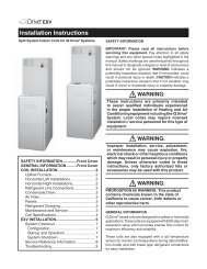
the job site. Ensure coil fins are straight and, ifnecessary, comb fins to remove flattened andbent fins.Preferred Location of the Outdoor Unit atJob Site — Conduct a survey of the job site todetermine the optimum location for mounting theoutdoor unit. Overhead obstructions, poorly ventilatedareas, and areas subject to accumulationof debris should be avoided. The outdoor unitshould be installed no closer than 18 inches fromthe outside walls of the facility and in an area freefrom overhead obstructions to ensure unrestrictedairflow through the outdoor unit.Facility Prerequisites — Electrical power mustbe supplied to the equipment. Electrical powersupplied must be adequate for proper operationof the equipment. The system must be wired andprovided with circuit protection in accordance withlocal building codes and the National ElectricalCode.Minimum Circuit Ampacity — Electrical wiringto the equipment must be compatible and incompliance with the minimum circuit ampacitylisted on the outdoor unit data label.Maximum Fuse/Circuit Breaker Size — Circuitprotection for the outdoor unit must be compatiblewith the maximum fuse/circuit breaker size listedon the outdoor unit data label.4. INSTALLING THE OUTDOORUNITSlab Mount — The site selected for a slab mountinstallation requires a stable foundation and onenot subject to erosion. The slab should be leveland anchored (if necessary) prior to placing theequipment on the slab.Cantilever Mount — The cantilever mountshould be designed with adequate safety factorto support the weight of the equipment, and forloads subjected to the mount during operation.Installed equipment should be adequately securedto the cantilever mount and levelled priorto operation of the equipment.Roof Mount — The method of mounting shouldbe designed so as not to overload roof structuresnor transmit noise to the interior of the structure.Refrigerant and electrical line should be routedthrough suitably waterproofed openings to preventwater leaking into the structure.WARNING:To avoid the risk of property damageor personal injury, it is the rigger’sresponsibility to ensure thatwhatever means are used to hoistthe unit are safe and adequate.5. INSTALLING THE INDOOR UNITThe indoor section should be installed beforeproceeding with routing of refrigerant piping.Consult the installation instructions of the indoorunit (i.e.: air handler, furnace, etc.) for detailsregarding installation.6. CONNECTING REFRIGERANTTUBING BETWEEN THEINDOOR AND OUTDOOR UNITGeneral — Once outdoor and indoor unit placementhas been determined, route refrigeranttubing between the equipment in accordance withsound installation practices. Refrigerant tubingshould be routed in a manner that minimizes thelength of tubing and the number of bends in thetubing. Refrigerant tubing should be supported ina manner that the tubing will not vibrate or abradeduring system operation. Tubing should be keptclean of foreign debris during installation. Everyeffort should be made by the installer to ensurethat the fi eld installed refrigerant containingcomponents of the system have been installedin accordance with these instructions and soundinstallation practices so as to insure reliablesystem operation and longevity. The maximumrecommended interconnecting refrigerant linelength is 75 feet, and the vertical elevation differencebetween the indoor and outdoor sectionsshould not exceed 20 feet.Optional Equipment — Optional equipment(e.g.: liquid line solenoid valves, twinning kit,low ambient,etc.) should be installed in strictaccordance with the manufacturer’s installationinstructions.4