708619-0 S3BN AC Commercial II.indd - Nordyne
708619-0 S3BN AC Commercial II.indd - Nordyne
708619-0 S3BN AC Commercial II.indd - Nordyne
- No tags were found...

You also want an ePaper? Increase the reach of your titles
YUMPU automatically turns print PDFs into web optimized ePapers that Google loves.
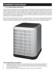
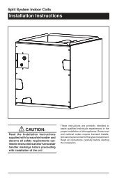
Outdoor Air ConditionerUser’s Information and Installation Instructions<strong>S3BN</strong> Series High Efficiency <strong>Commercial</strong> Split SystemThese units have been designed and tested for capacity and efficiency in accordancewith A.R.I. Standards. Split System Air Conditioner units are designedfor use with a wide variety of fossil fuel furnaces, electric furnaces, air handlers,and evaporator coil combinations.These instructions are primarily intended to assist qualified individuals experiencedin the proper installation of heating and/or air conditioning appliances.Some local codes require licensed installation/service personnel for this type ofequipment. Read all instructions carefully before starting the installation.
USER’S INFORMATIONIMPORTANTRead this owner information to become familiarwith the capabilities and use of your appliance.Keep this with literature on other applianceswhere you have easy access to it in the future.If a problem occurs, check the instructions andfollow recommendations given. If these suggestionsdon’t eliminate your problem, call yourservicing contractor .OPERATING INSTRUCTIONSTo Operate Your Air Conditioner forCooling —1. Set the thermostat system switch to COOLor AUTO and the thermostat fan switch toAUTO. (See Figure 1)2. Set the thermostat temperature to thedesired temperature level by pressing theWARMER or COOLER button. Please referto the separate detailed thermostat user’smanual for complete instructions regardingthermostat programming. The outdoor unitand indoor blower will both cycle on and offto maintain the indoor temperature at thedesired cooling level.To Operate Your Furnace for Heating —1. Set the thermostat system switch to HEATor AUTO and the thermostat fan switch toAUTO. (See Figure 1)2. Set the thermostat temperature to thedesired temperature level by pressing theWARMER or COOLER button. Please referto the separate detailed user’s manual forcomplete thermostat programming instructions.The furnace and indoor blower willcycle on and off to maintain the indoortemperature at the desired heating level.To Shut Off Your Air Conditioner —Set the thermostat system switch to OFF and thethermostat fan switch to AUTO. (See Figure 1).The system will not operate, regardless of thethermostat temperature setting.Figure 1. Typical ThermostatSet the thermostat fan switch to ON (See Figure1). The indoor blower will start immediately, andwill run continually until the fan switch is resetto AUTO.The continuous indoor blower operation can beobtained with the thermostat system switch setin any position, including OFF.The continuous indoor blower operation is typicallyused to circulate the indoor air to equalizea temperature unbalance due to a sun load,cooking, or fi replace operation.To Maintain Your Air Conditioner —CAUTION:Be certain the electrical powerto the outdoor unit and thefurnace/air handler is disconnectedbefore doing the followingrecommended maintenance.1. Regularly:a. Clean or replace the indoor air fi lter at thestart of each heating and cooling season,and when an accumulation of dust and dirtis visible on the air fi lter.b. Remove any leaves and grass clippingsfrom the coil in the outdoor unit, beingcareful not to damage the aluminum fi ns.To Operate the Indoor BlowerContinuously —2
CAUTION:Do not over-oil, or oil motors notfactory-equipped with oil tubes.The compressor is hermetically“sealed” and does not requirelubrication.c. Check for any obstructions, such as twigs,sticks, etc.2. Before Each Cooling Season:If the furnace/air handler blower motor andthe outdoor unit fan motor(s) have oil tubesat the motor bearings, apply 10 drops ofSAE No. 20 motor oil to each oil tube.3. Before Calling a Service Technician, BeCertain:a. The unit thermostat is properly set — see“To Operate Your Air Conditioner forCooling” and “To Operate Your Furnacefor Heating.”b. The unit disconnect fuses are in goodcondition, and the electrical power to theunit is turned on.1. GENERAL INFORMATIONRead the following instructions completely beforeperforming the installation.Condensing Unit Section — Each condensingunit is shipped with a refrigerant holding chargeadequate to maintain a positive pressure to keepout contaminants.NOTE: DO NOT USE ANY PORTION OF THECHARGE FOR PURGING OR LEAK TEST-ING.Liquid and Suction Lines — Refrigerant gradecopper tubing should be used when installing thesystem. Refrigerant suction line tubing shouldbe fully insulated.When condensing unit is matched with two airhandlers (two coils) or a dual circuited evaporatorcoil, refrigerant tubing should be branchedbetween both evaporator coils or circuits usingequal lengths of tubing to maintain equal evaporator/circuitperformance.Field Connections for Electrical Power Supply— All wiring must comply with current provisionsof the “National Electrical Code” (ANSI C1.) andwith applicable local codes having jurisdiction. Theminimum size of electrical conductors and circuitprotection must be in compliance with informationlisted on the outdoor unit data label.2. SAFETY CONSIDERATIONSPressures within the System — Split systemair conditioning equipment contains liquid andgaseous refrigerant under pressure. Installationand servicing of this equipment should beaccomplished by qualified, trained personnelthoroughly familiar with this type of equipment.Under no circumstances should non-qualifiedpersonnel attempt to install and/or service theequipment.Labels, Tags, Precautions — When workingwith this equipment, follow all precautions in theliterature, on tags, and on labels provided withthe equipment. Read and thoroughly understandthe instructions provided with the equipment priorto performing the installation and operationalcheckout of the equipment.Brazing Operations — Installation of equipmentmay require brazing operations. Safety codesmust be complied with. Safety equipment (e.g.;safety glasses, work gloves, fire extinguisher,etc.) must be used when performing brazingoperations.CAUTION:Ensure all electrical power to theunit is off prior to installing orservicing the equipment. Failureto do so may cause personal injuryor death.3. SITE PREPARATIONUnpacking Equipment — Remove the cardboardcarton and User’s Manual from the equipment.Take care not to damage the tubing connectionswhen removing the carton.Inspect for Damage — Inspect the equipmentfor damage prior to installing the equipment at3
the job site. Ensure coil fins are straight and, ifnecessary, comb fins to remove flattened andbent fins.Preferred Location of the Outdoor Unit atJob Site — Conduct a survey of the job site todetermine the optimum location for mounting theoutdoor unit. Overhead obstructions, poorly ventilatedareas, and areas subject to accumulationof debris should be avoided. The outdoor unitshould be installed no closer than 18 inches fromthe outside walls of the facility and in an area freefrom overhead obstructions to ensure unrestrictedairflow through the outdoor unit.Facility Prerequisites — Electrical power mustbe supplied to the equipment. Electrical powersupplied must be adequate for proper operationof the equipment. The system must be wired andprovided with circuit protection in accordance withlocal building codes and the National ElectricalCode.Minimum Circuit Ampacity — Electrical wiringto the equipment must be compatible and incompliance with the minimum circuit ampacitylisted on the outdoor unit data label.Maximum Fuse/Circuit Breaker Size — Circuitprotection for the outdoor unit must be compatiblewith the maximum fuse/circuit breaker size listedon the outdoor unit data label.4. INSTALLING THE OUTDOORUNITSlab Mount — The site selected for a slab mountinstallation requires a stable foundation and onenot subject to erosion. The slab should be leveland anchored (if necessary) prior to placing theequipment on the slab.Cantilever Mount — The cantilever mountshould be designed with adequate safety factorto support the weight of the equipment, and forloads subjected to the mount during operation.Installed equipment should be adequately securedto the cantilever mount and levelled priorto operation of the equipment.Roof Mount — The method of mounting shouldbe designed so as not to overload roof structuresnor transmit noise to the interior of the structure.Refrigerant and electrical line should be routedthrough suitably waterproofed openings to preventwater leaking into the structure.WARNING:To avoid the risk of property damageor personal injury, it is the rigger’sresponsibility to ensure thatwhatever means are used to hoistthe unit are safe and adequate.5. INSTALLING THE INDOOR UNITThe indoor section should be installed beforeproceeding with routing of refrigerant piping.Consult the installation instructions of the indoorunit (i.e.: air handler, furnace, etc.) for detailsregarding installation.6. CONNECTING REFRIGERANTTUBING BETWEEN THEINDOOR AND OUTDOOR UNITGeneral — Once outdoor and indoor unit placementhas been determined, route refrigeranttubing between the equipment in accordance withsound installation practices. Refrigerant tubingshould be routed in a manner that minimizes thelength of tubing and the number of bends in thetubing. Refrigerant tubing should be supported ina manner that the tubing will not vibrate or abradeduring system operation. Tubing should be keptclean of foreign debris during installation. Everyeffort should be made by the installer to ensurethat the fi eld installed refrigerant containingcomponents of the system have been installedin accordance with these instructions and soundinstallation practices so as to insure reliablesystem operation and longevity. The maximumrecommended interconnecting refrigerant linelength is 75 feet, and the vertical elevation differencebetween the indoor and outdoor sectionsshould not exceed 20 feet.Optional Equipment — Optional equipment(e.g.: liquid line solenoid valves, twinning kit,low ambient,etc.) should be installed in strictaccordance with the manufacturer’s installationinstructions.4
7. MAKING ELECTRICALCONNECTIONSWARNING:Turn off all electrical power at themain circuit box before wiringelectrical power to the outdoorunit. Failure to comply may causesevere personnel injury or death.Wiring Diagram/Schematic — A wiring diagram/schematicis located on the inside coverof the electrical box of the outdoor unit. Theinstaller should become familiar with the wiringdiagram/schematic before making any electricalconnections to the outdoor unit.Outdoor Unit Connections — The outdoorunit requires both power and control circuitelectrical connections. Refer to the unit wiringdiagram/schematic for identification and locationof outdoor unit field wiring interfaces.Supply Control Circuit Wiring — The outdoorunit is equipped with a 24 V<strong>AC</strong> Class ll transformerfor low voltage circuit control. Control circuit wiringmust comply with the current provisions of the“National Electrical Code” (ANSI C1.) and withapplicable local codes having jurisdiction. Whenusing two air handlers, a twinning kit (917453) isrequired for proper low voltage control wiring.Units are shipped factory wired for 240 or 460 voltoperation (see unit data label for proper incomingfi eld wiring). For 208 volt operation, removethe lead from the transformer terminal marked240V (on 208-230 models only) and connect it tothe terminal marked 208V. For maximum circuitampacity and maximum overcurrent protection,see the unit rating plate.Thermostat Connections — Thermostat connectionsshould be made in accordance with theinstructions supplied with the thermostat, andwith the instructions supplied with the indoorequipment.WARNING:To avoid the risk of electricalshock, personal injury, or death,disconnect all electrical powerto the unit before performing anymaintenance or service.WARNING:The unit cabinet must have anuninterrupted or unbroken electricalground to minimize personalinjury if an electrical fault shouldoccur. This ground may consist ofelectrical wire or approved conduitwhen installed in accordance withexisting national or local codes.Electrical Power Wiring:General — Electrical power wiring must bemade in accordance with all applicable localcodes and ordinances, and with the currentrevision of the National Electric Code NFPA 70or in Canada CSA C.22.1 Canadian ElectricalCode Part 1. If any of the original wire as suppliedwith the unit must be replaced, it must bereplaced with material of the same gauge andtemperature rating.Line Voltage — Before proceeding with the electricalconnections, make certain that the voltage,frequency and phase of the supply source arethe same as those specifi ed on the unit ratingplate. Also verify that the service provided by theutility is suffi cient to handle the additional loadimposed by this equipment.This unit must be electrically grounded in accordancewith local codes or, in the absence oflocal codes, with the National Electrical Code(ANSI/NFPA 70) or the CSA C22.1 ElectricalCode.See the unit wiring label for proper high and lowvoltage wiring. Make all electrical connectionsin accordance with all applicable codes andordinances.5
Use a separate branch electrical circuit for thisunit. A means of electrical disconnect must belocated within sight of and readily accessibleto the unit.Overcurrent protection must be provided at thebranch circuit distribution panel and sized asshown on the unit rating label and accordingto the National Electric Code and applicablelocal codes.Provide power supply for the unit in accordancewith the unit wiring diagram, and the unit ratingplate. Connect the line-voltage leads to theterminals on the contactor inside the controlcompartment. Use only copper wire for the linevoltage power supply to this unit. Use proper codeagency listed conduit and a conduit connector forconnecting the supply wires to the unit. Propergrounding is accomplished by using the groundinglug provided in the control box.Disconnect Switch — An electrically compatibledisconnect switch must be within line of sight ofthe outdoor unit. This switch shall be capable ofelectrically de-energizing the outdoor unit.Optional Equipment — Optional equipment requiringconnection to the power or control circuitsmust be wired in strict accordance with currentprovisions of the “National Electrical Code” (ANSIC1.), with applicable local codes having jurisdiction,and the installation instructions provided withthe equipment. Optional Equipment (e.g.: liquidline solenoid valves, twinning kit, low ambient,etc.) should be installed in strict accordance withthe manufacturer’s installation instructions.8. STARTUP AND CHECKOUTAir Filters — Ensure air filters are clean and inplace prior to operating the equipment.WARNING:Ensure electrical power to the unitis off prior to performing the followingsteps. Failure to do so maycause personal injury or death.Thermostat — Set the room thermostat functionswitch to OFF, fan switch to AUTO, and movetemperature setpoint to its highest setting.Prior to applying electrical power to the outdoorunit, ensure that the unit has been properlyand securely grounded, and that power supplyconnections have been made at both the facilitypower interface and outdoor unit.Outdoor Unit — Ensure the outdoor coil andtop of the unit are free from obstructions anddebris, and all equipment access/control panelsare in place.Using extreme caution, apply power to the unitand inspect the wiring for evidence of open,shorted, and/or improperly wired circuits.Functional Checkout:Indoor Blower — Set the thermostat fan switchto ON. Verify that the indoor blower is operatingand that airfl ow is not restricted. Set the fanswitch back to AUTO.CAUTION:If equipped with a compressorcrankcase heater, wait 24 hoursprior to performing a functioncheckout to allow for heating of thecompressor crankcase. Failure tocomply may result in damage andcould cause premature failure ofthe system.Cooling — Set the thermostat system switch to“Cool” and the thermostat fan switch to “Auto.”Lower the thermostat temperature switch belowroom temperature and ensure unit refrigerantpressures are in order.NOTE: If refrigerant pressures are abnormal,compressor may be rotating in the opposite direction.Shut off main power to the unit and switchany two fi eld wires at the disconnect. DO NOTalter unit wiring. Listen for any unusual noises.Locate the source and correct as needed.6
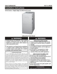
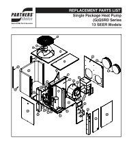
After allowing the unit to run for several minutes,set the temperature selector above roomtemperature, verify that the fan, blower, andcompressor cycle off with the thermostat.Short Cycle Protection — With the systemoperating in COOLING mode, note the setpointtemperature setting of the thermostat, andgradually raise the setpoint temperature untilthe outdoor unit and indoor blower de-energize.Immediately lower the setpoint temperature ofthe thermostat to its original setting and verifythat the indoor blower is energized and that theoutdoor unit remains de-energized. Verify that,after approximately 5 minutes, the outdoor unitenergizes and that the temperature of the airsupplied to the facility is cooler than ambienttemperature.Heating — If provided with heating equipment,lower the thermostat setpoint temperature to thelowest obtainable setting and set the thermostatfunction switch to HEATING. The indoor blowerand outdoor unit should stop running. Increasethe setpoint temperature of the thermostat tothe maximum setting. Verify that the heatingequipment has been energized (i.e., fossil fuelburner operating, etc.) and that the indoor blowerenergizes after a short period of time. Feel theair being circulated by the indoor blower andverify that it is warmer than ambient temperature.Listen for any unusual noises. If present, locateand determine the source of the noise and correctas necessary.NOTE: Other sources for heating (i.e.: electricfurnace, fossil fuel furnace, air handler withelectric heat options, etc.) that interface withthe heat pump should be functionally checkedto verify system operation and compatibility withthe heat pump. Refer to the installation instructionsfor this equipment and perform a functionalcheckout in accordance with the manufacturer’sinstructions.Adjustment of Refrigerant Charge:CAUTION:Split system air conditioningequipment contains liquid and gaseousrefrigerant under pressure.Adjustment of refrigerant chargeshould only be attempted by qualified,trained personnel thoroughlyfamiliar with the equipment. Underno circumstances shouldthe homeownerattempt to install and/orservice this equipment. Failureto comply with this warning couldresult in equipment damage, personalinjury, or death.NOTE: The following Refrigerant ChargingCharts are applicable to matched assembliesof our equipment and at listed airfl ows for theindoor coil. Assemblies of indoor coils andoutdoor units not listed are not recommendedand deviations from rated airfl ows or non-listedequipment combinations may require modifi cationsto the expansion device(s) and refrigerantcharging procedures for proper and effi cientsystem operation.Refrigerant Charging Chart — Refer to RefrigerantCharging Charts for correct systemcharging.Optional Equipment — A functional checkoutshould be performed in accordance with thecheckout procedures supplied with the equipment.7
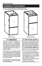
Refrigerant Charging Charts4003753503253002752502252001751507.5 Ton <strong>AC</strong> TXV Charging ChartRemove refrigerant when above curveAdd refrigerant when below curve75 80 85 90 95 100 105 110 115 120 125 130 135Liquid Temperature (F)Liquid Pressure (psig)8
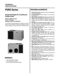
Refrigerant Charging Charts40037535032530027525022520017515010 Ton <strong>AC</strong> TXV Charging ChartRemove refrigerant when above curveAdd refrigerant when below curve75 80 85 90 95 100 105 110 115 120 125 130 135Liquid Temperature (F)Liquid Pressure (psig)9
Notes: 1) Disconnect all power before servicing.2) For supply connections use copper conductors only.3) Furnace/Air Handler w/factory equipped 24 V control circuit transformers, should bemodified/rewired to ONLY use 24V transformer from outdoor section. See installationinstructions for typical modifications.4) For replacement wires use conductors suitable for 105° C.5) For ampacities and overcurrent protection, see unit rating plate.1) Couper le courant avant de faire letretien.2) Employez uniquement des conducteurs en cuivre.L1 L2 L3CC CC CCBL<strong>AC</strong>KOUTDOOR FANMOTORSRCCCHCOMPRESSORT2T3T1BL<strong>AC</strong>KREDBL<strong>AC</strong>KBL<strong>AC</strong>KYELLOWCOMPRESSORT1 T2 T3CONT<strong>AC</strong>TORLOW PRESSURESWITCHHIGH PRESSURESWITCHT2T3T1L1 L2 L3PURPLEBL<strong>AC</strong>KBL<strong>AC</strong>KGREENYELLOWC SRORANGEREDBL<strong>AC</strong>KASCTASCTCCR Y CHIGH PRESSURESWITCHLOW PRESSURESWITCHField WiringHigh VoltageLow VoltageFactory WiringHigh VoltageLow VoltageORANGEOUTDOOR FANMOTOR3-PHASE SUPPLYVOLTAGEWHITEBL<strong>AC</strong>KRYCANTI-SHORT-CYCLE TIMERISOLATED T-STAT CONT<strong>AC</strong>T24V FOR INDOORCONTROL CIRCUIT710709010
PHYSICAL AND ELECTRICAL SPECIFICATIONS / OUTDOOR UNITS10.3 EER —High Efficiency — Three PhaseModel No. <strong>S3BN</strong>- 090C 090W 120C 120WElectrical Data280/230-3-60 460-3-60 280/230-3-60 460-3-60Volts-Phase-Hz380/420-3-50 380/420-3-50Voltage Range (Min-Max) 187-253 414-506 187-253 414-506Total Amps 32.1 16.4 33.4 17.2Min Circuit Ampacity 41.4 21.7 43 22.7Delay Fuse Max. (1) 60 35 70 35Wire Size/Max Length (AWG 60°C Cu) 4/100 8/100 4/100 8/100Wire Size/Max Length (AWG 75°C Cu) 6/100 8/100 4/100 8/100Component Data Coil Area (ft^2) 31.94 31.94 31.94 31.94Rows-FPI 2-16 2-16 2-18 2-18Tube Dia. 3/8” OD 3/8” OD 3/8” OD 3/8” ODFan Motor280/230-3-60 460-3-60 280/230-3-60 460-3-60Volts-Phase-Hz380/420-3-50 380/420-3-50Qty 1 1 1 1Horsepower 3/4 3/4 3/4 3/4Full Load Amps 3.3 1.7 3.3 1.7Fan Blade Dia./Pitch/#Blades 30/19/3 30/19/3 30/26/3 30/26/3RPM/CFM (Max-Total) 825/7500 825/7500 825/8500 825/8500Compressor Volts-Phase-Hz 280/230-3-60 460-3-60 280/230-3-60 460-3-60DataQty./Type 1 / Scroll 1 / Scroll 1 / Scroll 1 / ScrollRLA 28.8 14.7 30.1 15.5LRA 195 95 225 114Stages/Percent 1 / 100 1 / 100 1 / 100 1 / 100Crankcase Heater Qty./Type 1 / Band 1 / Band 1 / Band 1 / BandRefrigerant Suction Line-Length/O.D. 0 - 15 ft. 1 1/8” 1 1/8” 1 1/8” 1 1/8”(Liq. Line All Lengths - 5/8” O.D.) 16 - 25 ft 1 3/8” (3) 1 3/8” (3) 1 3/8” (3) 1 3/8” (3)Circuits (Qty) - 1 26 - 75 ft. 1 3/8” (3) 1 3/8” (3) 1 3/8” (3) 1 3/8” (3)Refrigerant Charge Holding 56 56 90 90R-22 Ounces Total System with 15’ Line Set (2) 374 374 430 430Weight Net 395 395 405 405Approximate (lbs.) Ship 407 407 417 417(1) H<strong>AC</strong>R Type Circuit Breakers may be used.(2) Add 9.0 oz. of refrigerant per 5 feet of additional line set.(3) Requires a 1-3/8” to 1-1/8” reducer line to unit.<strong>AC</strong>CESSORIES —Condensing UnitLow Ambient Kit 913549A- Maintains systempressures during low ambient conditions.COPPER WIRE SIZE — AWG(1% Voltage Drop)Supply Wire Length-Feet Supply Circuit200 150 100 50 Ampacity6 8 10 14 154 6 8 12 204 6 8 10 254 4 6 10 303 4 6 8 353 4 6 8 402 3 4 6 452 3 4 6 502 3 4 6 551 2 3 4 60Wire Size based on N.E.C. for 60° type copperconductors.11
INSTALLER:PLEASE LEAVE THESEINSTALLATION INSTRUCTIONSWITH THE HOMEOWNER¢<strong>708619</strong>G¤<strong>708619</strong>0<strong>708619</strong>0Specifications and illustrations subject to changewithout notice and without incurring obligations.Printed in U.S.A. (07/07)