Part # 12176799 97-03 F-150 AirBar - Air Ride Technologies
Part # 12176799 97-03 F-150 AirBar - Air Ride Technologies
Part # 12176799 97-03 F-150 AirBar - Air Ride Technologies

Create successful ePaper yourself
Turn your PDF publications into a flip-book with our unique Google optimized e-Paper software.
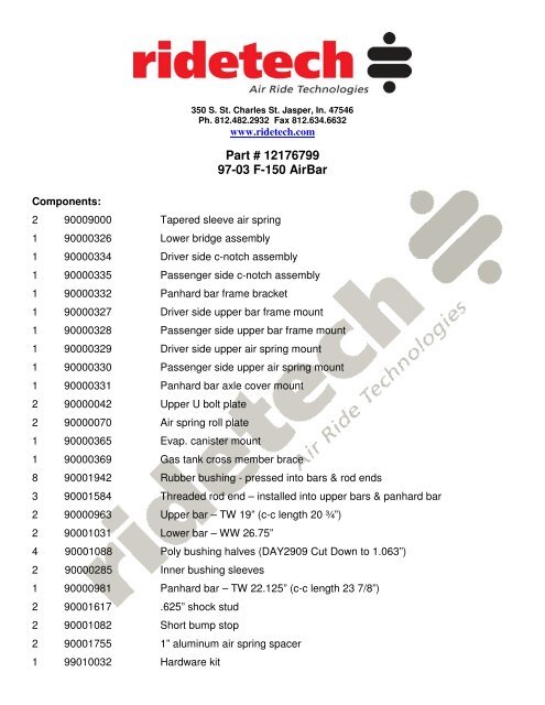
Components:<br />
350 S. St. Charles St. Jasper, In. 47546<br />
Ph. 812.482.2932 Fax 812.634.6632<br />
www.ridetech.com<br />
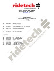
<strong>Part</strong> # <strong>12176799</strong><br />
<strong>97</strong>-<strong>03</strong> F-<strong>150</strong> <strong><strong>Air</strong>Bar</strong><br />
2 90009000 Tapered sleeve air spring<br />
1 9000<strong>03</strong>26 Lower bridge assembly<br />
1 9000<strong>03</strong>34 Driver side c-notch assembly<br />
1 9000<strong>03</strong>35 Passenger side c-notch assembly<br />
1 9000<strong>03</strong>32 Panhard bar frame bracket<br />
1 9000<strong>03</strong>27 Driver side upper bar frame mount<br />
1 9000<strong>03</strong>28 Passenger side upper bar frame mount<br />
1 9000<strong>03</strong>29 Driver side upper air spring mount<br />
1 9000<strong>03</strong>30 Passenger side upper air spring mount<br />
1 9000<strong>03</strong>31 Panhard bar axle cover mount<br />
2 90000042 Upper U bolt plate<br />
2 90000070 <strong>Air</strong> spring roll plate<br />
1 9000<strong>03</strong>65 Evap. canister mount<br />
1 9000<strong>03</strong>69 Gas tank cross member brace<br />
8 90001942 Rubber bushing - pressed into bars & rod ends<br />
3 90001584 Threaded rod end – installed into upper bars & panhard bar<br />
2 90000963 Upper bar – TW 19” (c-c length 20 ¾”)<br />
2 90001<strong>03</strong>1 Lower bar – WW 26.75”<br />
4 90001088 Poly bushing halves (DAY2909 Cut Down to 1.063”)<br />
2 90000285 Inner bushing sleeves<br />
1 90000981 Panhard bar – TW 22.125” (c-c length 23 7/8”)<br />
2 90001617 .625” shock stud<br />
2 90001082 Short bump stop<br />
2 90001755 1” aluminum air spring spacer<br />
1 99010<strong>03</strong>2 Hardware kit
350 S. St. Charles St. Jasper, In. 47546<br />
Ph. 812.482.2932 Fax 812.634.6632<br />
www.ridetech.com<br />
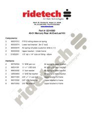
<strong>Part</strong> # 99010<strong>03</strong>2 Hardware Kit<br />
Note: front lower bar utilizes oem spring hanger bolt<br />
8 5/8 x 6 sae bolts grade 8 bridge to axle assembly<br />
16 5/8 sae flat washers grade 8 bridge to axle assembly<br />
8 5/8 sae nyloc nuts grade 8 bridge to axle assembly<br />
8 5/8 x 2 ¾ sae bolts grade 8 rod ends<br />
8 5/8 sae nyloc jam nuts rod ends<br />
2 ½ x 2 ½ uss bolts lower shock mounting<br />
10 ½ uss nyloc nuts 2=lower shock mounting / 8=upper front bar mount<br />
8 ½ x 1 ½ uss bolts front upper bar mount<br />
16 ½ uss flat washers front upper bar mount<br />
33 7/16 x 1 ½ uss bolts c-notch to frame<br />
66 7/16 uss flat washers c-notch to frame<br />
33 7/16 uss nyloc nuts c-notch to frame<br />
2 3/8 x 1 ¾” USS bolt lower air spring mount<br />
6 3/8 x 1 uss bolts airspring mounting / gas tank x-member<br />
6 3/8 lock washers airspring mounting<br />
10 3/8 sae flat washers airspring mounting / gas tank x-member<br />
2 3/8 uss nyloc nuts gas tank x-member<br />
2 3/8 x 1 ¼ uss bolts upper airspring mount<br />
2 3/8 x 1 ½ uss bolts upper airspring mount<br />
4 3/8 x ¾ uss bolts upper airspring mount<br />
4 7/16 uss flat washers upper airspring mount<br />
4 3/8 uss nyloc nuts upper airspring mount<br />
12 3/8 sae flat washers upper airspring mount<br />
4 3/8 lock washers upper airspring mount<br />
3 5/16 x 1 uss bolts axle cover bracket<br />
3 5/16 sae flat washers axle cover bracket<br />
3 5/16 lock washers axle cover bracket<br />
3 ¼ x 1 uss bolts evap. canister<br />
6 ¼ uss flat washers evap. canister<br />
3 ¼ uss nyloc nuts evap. canister<br />
<strong>97</strong> to Present Ford F<strong>150</strong> <strong>Air</strong>bar
Installation instructions<br />
1. Raise vehicle to a comfortable working height and support the frame with jackstands ahead of the leafspring<br />
hangar and also behind the axle center.<br />
2. Remove wheels and tires.<br />
3. Remove bed.<br />
4. The C notch framerail section will be<br />
installed first. Use the C notch as the<br />
template. Line up the bumpstop positions<br />
on the new C notch and the OEM<br />
framerail to determine exact position of<br />
C notch. Then scribe the outline of the<br />
notch onto the framerail and cut out that<br />
section using a sawzall, cutoff wheel or<br />
other appropriate tool. NOTE: Using a<br />
torch make a huge mess and increases<br />
that chance of fire or other accident. BE<br />
CAREFUL!<br />
5. After the framerail is cut, slide the C<br />
notch over the frame and use it as a<br />
template to mark and drill the attachment<br />
holes. The C notch will be a snug fit and<br />
may require a few light taps to get<br />
positioned properly.<br />
6. Install the upper bar frame brackets. This will<br />
require removal of 2 of the attachment rivets on the<br />
OEM leafspring hangar. The new frame bracket will<br />
index off of these two points. You will need to drill<br />
the remaining attachment holes using the bracket as<br />
the template.
7. Install the axle bracket bridge assembly. This assembly is installed underneath the axle and is<br />
indexed off the bottom of the OEM leafspring pads. The upper bar axle mounts are then set on top of<br />
the OEM leafspring pads and the entire assembly is bolted together with the supplied grade 8 bolts,<br />
washers and nuts. A second set of hands is helpful during this procedure. NOTE: At some point<br />
during the installation the OEM tailpipe will need to be removed for clearance. A custom tailpipe or a<br />
turndown out of the muffler will be necessary to properly complete the <strong><strong>Air</strong>Bar</strong> installation. If you let the<br />
exhaust blow back on the ailines and airsprings, damage will certainly result.<br />
8. Remove the 3 bolts in the right hand corner of the axle cover. Bolt on the panhard bar axle mount.<br />
The other side will bolt to the frame bracket.
9. The bracket shown<br />
to the left was there to<br />
locate the spare tire. It<br />
will be removed as<br />
shown to the right to<br />
provide room for the<br />
upper airspring mount.<br />
8. Install the 4 link bars into the frame<br />
and axle brackets. The long bars will go<br />
into the bottom brackets. The adjustable<br />
end should go into the frame brackets.<br />
The bars are pre-adjusted to length at<br />
the factory, but double check that they<br />
are indeed the same length from side to<br />
side.
10. The emissions canister will also need to be<br />
modified slightly as shown to accept new mounting<br />
bracketry.<br />
NOTE: Not all models will have this configuration of<br />
the emissions canister.<br />
11. The photo to the left shows the new<br />
drivers side emissions canister mounting<br />
[provided] that is necessary to clear the new<br />
upper airspring mounts. This also shows the<br />
upper airspring mount attachment through<br />
the OEM shock mount and 2 other existing<br />
holes.<br />
12. Passenger side bottom view of the<br />
upper airspring mount. Hidden is the ear<br />
that attaches to the C notch. There will be 2<br />
bolts that are installed from the top into a<br />
threaded bung on the airspring mount and<br />
an ear that is bolted to the C notch. The<br />
fourth hole should line up with the OEM<br />
upper shock mount<br />
13. The airsprings can now be installed. Be sure to use Teflon tape or paste on the airline fitting threads to<br />
avoid air leaks. Also be sure to use the provided plate under the airsprings for proper support.
14. Install the provided shocks into the<br />
upper and lower shock mounts. If using a<br />
shock other than ours, be sure the shock<br />
does not bottom out but will capture the<br />
suspension before overextending the<br />
airspring. [note possible location for air<br />
tank]<br />
15. The fuel tank crossmember must be sectioned for driveshaft clearance at full drop. The<br />
photo on the left shos the OEM crossmember with the marks for cutting. Use a sawzall or cutoff<br />
wheel to cut out a section approx. 5” wide The photo on the right shows the cut crossmember .<br />
The fuel tank strap bolt must be repositioned approx. 1.25” outboard and the muffler heat shield<br />
must be trimmed approx. 1”<br />
16. Install the provided fuel tank crossmember support onto the top of the crossmember to restore the strength<br />
to the modified crossmember.<br />
NOTE: WHEN LIFTING THE VEHICLE BY THE FRAME, BE SURE TO DEFLATE THE AIRSPRINGS AT<br />
LEAST PARTIALLY TO MINIMIZE STRESS ON THE EXTENDED AIRSPRING.<br />
NOTE: IT IS THE FINAL RESPONSIBILITY OF THE INSTALLER TO ENSURE THAT THE<br />
AIRSPRING DOES NOT RUB ON ANYTHING! ABRASION WILL CAUSE IMMEDIATE AND FATAL<br />
DAMAGE TO THE AIRSPRING!!!