Part # 11009501 Universal Air Spring Installation Kit (w/ F6873's) 2 ...
Part # 11009501 Universal Air Spring Installation Kit (w/ F6873's) 2 ...
Part # 11009501 Universal Air Spring Installation Kit (w/ F6873's) 2 ...

You also want an ePaper? Increase the reach of your titles
YUMPU automatically turns print PDFs into web optimized ePapers that Google loves.
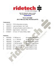
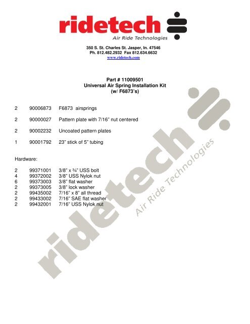
350 S. St. Charles St. Jasper, In. 47546Ph. 812.482.2932 Fax 812.634.6632www.ridetech.com<strong>Part</strong> # <strong>11009501</strong><strong>Universal</strong> <strong>Air</strong> <strong>Spring</strong> <strong>Installation</strong> <strong>Kit</strong>(w/ F6873’s)2 90006873 F6873 airsprings2 90000027 Pattern plate with 7/16” nut centered2 90002232 Uncoated pattern plates1 90001792 23” stick of 5” tubingHardware:2 99371001 3/8” x ¾” USS bolt4 99372002 3/8” USS Nylok nut6 99373003 3/8” flat washer2 99373005 3/8” lock washer2 99435002 7/16” x 8” all thread2 99433002 7/16” SAE flat washer2 99432001 7/16” USS Nylok nut
INSTALLATION INSTRUCTIONSFRONT SYSTEM1.Determine ride height of vehicle. On an existing vehicle, remove your present springs and use afloor jack to adjust vehicle height. Be sure to maintain a reasonable ground clearance,. Rememberthat you will have 3 to 4 inches of downward adjustment from this point. On most vehicles, the lowerA arms should be approximately level at ride height. [ Ride height refers to the level at which thevehicle will travel down the road, airsprings inflated.] Record the spindle measurement and the fenderlip measurement so this relationship can be re-created at a comfortable working height.2. Attach the air spring to the lower bracket and attach the assembly to the lower A arm. Make surethe air spring does not contact any part of the car at any time!THE AIR SPRING BELLOWS MUST NOT CONTACT ANYTHING AT ANYTIME!!!Set the airspring as far toward the wheel as possible while avoiding steering linkage, brake caliperssway bars brake lines, etc.3. With the spindle at ride height, attach the upper bracket to the airspring. Make sure the airspring isalso at ride height. You may have to compress the airspring slightly to the correct installed heightdimension included with your system. If you are unsure about this dimension, call us and we cangive it to you..4. With the airspring and bracket assembly in place, you can now determine the location of theupper bracket. Clamp the bracket in place for marking holes or for welding. Double check theclearance around the airspring in all wheel positions and all steering angles. You will also want tocheck for proper ground clearance [at least 2 “] when the airspring is completely deflated. Rememberthat a bump stop should be used to maintain proper ground clearance when the airspring iscompletely deflated.5. Remove the airspring to do the final welding. The airspring has NO tolerance for weld splatter!6. Shock absorber mounting is next. The bottom of the shock is mounted to the lower A arm. The topof the shock is mounted to the frame. With the A arm at full droop,[max airspring height dimension]trial fit the shock to avoid interference with steering and brake components. Make sure that the shockdoesn’t bottom out before the airspring is completely deflated.[vehicle on bumpstops. Refer to min.height dimension.]REAR SYSTEM1. Set rear of vehicle at ride height. You may have to remove the coilsprings or some of the leafs tolet the vehicle settle to the desired ride height. Remember that this is the height that you want the carto go down the road at. You will have approx. 4” of drop available from this point.[Note: You mustleave at least 2 leafs in the leafspring pack for lateral stability. If the vehicle is not low enough at thatpoint, a 4 link or ladder bar suspension should be considered.]Continued....2. Record measurement of axle and fender lip so this relationship can be recreated at a comfortableworking height.3. When the vehicle is safely supported by the frame at working height, install the lower airspringbracket onto the axle tube level with the car.[not necessarily level with the ground.] Be aware of anyinterference from exhaust, brake lines, suspension components, etc. Refer to the dimension chart for
the inflated diameter of the airspring. It may be substantially larger than the uninflated diameter.REMEMBER: THE AIRSPRING MUST NOT TOUCH ANYTHING AT ANYTIME!!4.Install the airspring onto the lower bracket and use it to determine the location of the upper bracket.A good alternative to this is to use a length of thread stock with some nuts and washers to simulatethe airspring at ride height. This insures proper alignment of the upper and lower brackets and willhold the upper bracket steady while it is being attached to the vehicle.5. Attach the upper bracket to the vehicle with bolts or by welding. remember that the airspring hasno tolerance to weld splatter!6. The shock mounting for the rear may have to be modified. Make sure the minimum and maximumheight dimensions for the airspring are not exceeded. Bumpstops must be installed to restrict themaximum compression and extension of the rearend. Usually a rubber snubber works well forcompression and the shock absorber mounting restricts the extension.COMPRESSOR MOUNTING AND AIRLINE ROUTING1. The air compressor and reservoir may be mounted in any convenient location. A 12v power wire of12ga or larger with a 20amp inline fuse will be required. This power wire should be run directly to thebattery. The fuse should be placed as close to the battery as possible. A 120psi pressure switch issupplied to activate the compressor according to pressure requirements. The RED wire from thecompressor and the 12v positive wire from the battery are connected to the terminals of this switch[either terminal]. Vibration mounts are supplied with the compressor to aid in noise reduction.2. The airline fittings supplied are the push-to-connect style. The plastic airline must be cut clean andsquare to seal properly. A safety razor works well. A diagonal cutters does not.3. The airlines should be kept away from exhaust, moving components and sharp edges.4. The control panel[s] should be mounted in a convenient location to the driver. The wires extendingfrom the controller are for gauge illumination. One wire will be connected to a suitable powersource,[one that is hot when your lights are on] and the other will be connected to ground.After finishing the installation, please double check the clearance around each airspring through theentire wheel travel and the steering travel. Be sure to check for proper tire clearance and for properground clearance throughout the entire suspension movement. Take the vehicle for a short test driveand check it again.REMEMBER:THE AIRSPRING BELLOWS MUST NOT TOUCH ANY THING AT ANYTIME!A MINIMUM OF 2” OF GROUND CLEARANCE MUST BE MAINTAINED WHEN THE AIRSPRINGIS COMPLETELY DEFLATED.If you have any questions concerning the air ride system, please don’t hesitate to call us. we want toinsure that your installation is done as safely as possible, and that it will be reliable for years to come.AIR RIDE TECHNOLOGIES
Bair inletATopBottomDoubleConvoluted812.482.2932CompressedRide HeightExtendedTaperedSleeveTopRollingSleeveTopAIRSPRING DIMENSION CHARTPART# TYPE Capacity@ Compres Ride Height Max. Max Bolt Pattern100psi s HeightHeight Diameter255C Double 2040# 3” 4.5”-5.5” 7” 6.5” A=1.75 B=.875[F6957] Convoluted224C Double 3150# 3” 5”-6” 8” 8.0” A=2.75 B=1.312[F0335 Convoluted26C Double 3400# 3” 5”-6” 10” 8.5” A=2.75 B=1.312[F7325] Convoluted20 Double 4790# 3” 7”-8” 11” 9.9” A=3.50 B=1.75[F6908] ConvolutedF9000 Tapered 1500# 4.5 8”-9” 12” 5” A=2.75 B=1.312SleeveF9002 Tapered 1500# 4.5 7”-8.” 11” 5” A=2.75 B=1.312SleeveF9003 Tapered 1500# 4.5 6.5”-7” 10.5” 5” A=2.75 B=1.312SleeveF9010 TaperedSleeve2000# 6.5” 10.5”-11.5” 16” 6.5” .750SAE/.250npt7012 RollingSleeve1020# 4” 7.5”-8.5” 13” 5” .750SAE/.125npt7076 RollingSleeve800# 3.5” 5”-6” 9” 4” .750SAE/.125nptCAUTION!!! EXCEEDING THESE DIMINSIONS MAY RESULT IN SUDDEN AIRSPRING FAILURE!PROPER CLEARANCES MUST BE MAINTAINED AT ALL RIDE HEIGHTS AND STEERINGANGLES. BUMPSTOPS MUST BE USED TO LIMIT SUSPENSION TRAVEL BEFORE THESEDIMENSIONS ARE EXCEEDED.PLEASE CALL AIR RIDE TECHNOLOGIES IF YOU HAVE ANY QUESTIONS.
Rear suspension w/ 4 link and air rideMustang II w/ tubular control arm [rear view]Mustang II w/ tubular control arm [front view]
Aftermarket Mustang II installation[replaces coilover shock]Mustang II w/ tubular armCamaro / Nova installationOptional upper front shock mountingMustang II front end fully compressedRear “pro street “ installation [fully extended]