CompuScope SDK for L.. - Egmont Instruments
CompuScope SDK for L.. - Egmont Instruments
CompuScope SDK for L.. - Egmont Instruments
- No tags were found...
You also want an ePaper? Increase the reach of your titles
YUMPU automatically turns print PDFs into web optimized ePapers that Google loves.
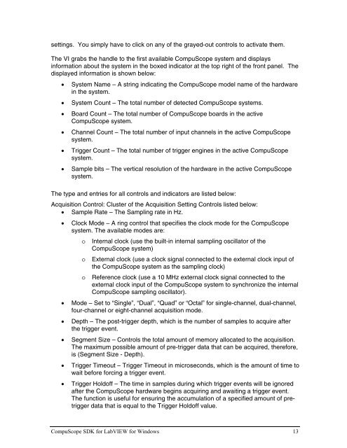
settings. You simply have to click on any of the grayed-out controls to activate them.The VI grabs the handle to the first available <strong>CompuScope</strong> system and displaysin<strong>for</strong>mation about the system in the boxed indicator at the top right of the front panel. Thedisplayed in<strong>for</strong>mation is shown below:• System Name – A string indicating the <strong>CompuScope</strong> model name of the hardwarein the system.• System Count – The total number of detected <strong>CompuScope</strong> systems.• Board Count – The total number of <strong>CompuScope</strong> boards in the active<strong>CompuScope</strong> system.• Channel Count – The total number of input channels in the active <strong>CompuScope</strong>system.• Trigger Count – The total number of trigger engines in the active <strong>CompuScope</strong>system.• Sample bits – The vertical resolution of the hardware in the active <strong>CompuScope</strong>system.The type and entries <strong>for</strong> all controls and indicators are listed below:Acquisition Control: Cluster of the Acquisition Setting Controls listed below:• Sample Rate – The Sampling rate in Hz.• Clock Mode – A ring control that specifies the clock mode <strong>for</strong> the <strong>CompuScope</strong>system. The available modes are:oooInternal clock (use the built-in internal sampling oscillator of the<strong>CompuScope</strong> system)External clock (use a clock signal connected to the external clock input ofthe <strong>CompuScope</strong> system as the sampling clock)Reference clock (use a 10 MHz external clock signal connected to theexternal clock input of the <strong>CompuScope</strong> system to synchronize the internal<strong>CompuScope</strong> sampling oscillator).• Mode – Set to “Single”, “Dual”, “Quad” or “Octal” <strong>for</strong> single-channel, dual-channel,four-channel or eight-channel acquisition mode.• Depth – The post-trigger depth, which is the number of samples to acquire afterthe trigger event.• Segment Size – Controls the total amount of memory allocated to the acquisition.The maximum possible amount of pre-trigger data that can be acquired, there<strong>for</strong>e,is (Segment Size - Depth).• Trigger Timeout – Trigger Timeout in microseconds, which is the amount of time towait be<strong>for</strong>e <strong>for</strong>cing a trigger event.• Trigger Holdoff – The time in samples during which trigger events will be ignoredafter the <strong>CompuScope</strong> hardware begins acquiring and awaiting a trigger event.The function is useful <strong>for</strong> ensuring the accumulation of a specified amount of pretriggerdata that is equal to the Trigger Holdoff value.<strong>CompuScope</strong> <strong>SDK</strong> <strong>for</strong> LabVIEW <strong>for</strong> Windows 13


