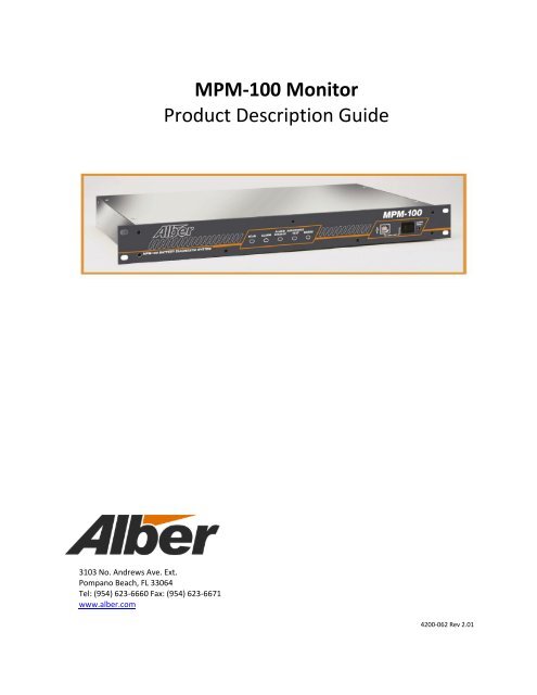
MPM-100 Monitor Product Description Guide - Alber
MPM-100 Monitor Product Description Guide - Alber
MPM-100 Monitor Product Description Guide - Alber
Create successful ePaper yourself
Turn your PDF publications into a flip-book with our unique Google optimized e-Paper software.
<strong>MPM</strong>-<strong>100</strong> <strong>Monitor</strong><strong>Product</strong> <strong>Description</strong> <strong>Guide</strong>3103 No. Andrews Ave. Ext.Pompano Beach, FL 33064Tel: (954) 623-6660 Fax: (954) 623-6671www.alber.com4200-062 Rev 2.01
Copyright and Disclaimer<strong>MPM</strong>-<strong>100</strong> <strong>Product</strong> <strong>Description</strong> <strong>Guide</strong>Document Revision 2.01Part Number 4200-062Revision HistoryRevision Date of Change <strong>Description</strong> of Change By2.00 11/04/2004 Original Document ED2.01 01/26/2012 Minor edits and reformatting and pagination MSAlbér <strong>MPM</strong>-<strong>100</strong> <strong>Product</strong> <strong>Description</strong> <strong>Guide</strong> Part Number 4200–062©2012 Albércorp. All rights reserved.Albércorp, 3103 North Andrews Avenue Extension, Pompano Beach FL 33064.No part of this document may be reproduced or transmitted in any form or by any means, electronicor mechanical, including photocopying and recording for any purpose, without the express writtenpermission of Albércorp.Information in this document is subject to change without notice.TrademarksThe first instances of registered trademarks or trademarks of Albércorp and other companies areannotated above using the ® and symbols. For ease of reading, these symbols do not appear in theremainder of this <strong>Product</strong> <strong>Description</strong> <strong>Guide</strong>.Printed in the United States of America.4200–062 2 Revision 2.01
Table of Contents1. <strong>MPM</strong>-<strong>100</strong> GENERAL DESCRIPTION ........................................................................................................................ 11.1. Normal Operating Mode ......................................................................................................................... 11.2. Discharge Mode ...................................................................................................................................... 11.3. Resistance Test Mode ............................................................................................................................. 11.4. Alarm Features ....................................................................................................................................... 11.5. Controlled Run Down Test ..................................................................................................................... 21.6. <strong>MPM</strong>-<strong>100</strong> Features ................................................................................................................................. 21.7. Battery <strong>Monitor</strong> Data Manager (BMDM) Program Features ................................................................. 21.8. Optional and additional Accessories ....................................................................................................... 32. PANEL CONTROLS AND INDICATORS ............................................................................................................... 52.1. Panel Controls and Indicators ................................................................................................................. 53. <strong>MPM</strong>-<strong>100</strong> CONFIGURATIONS .......................................................................................................................... 83.1. <strong>MPM</strong> Model Number <strong>Description</strong> .......................................................................................................... 83.2. <strong>MPM</strong> Configuration Options .................................................................................................................. 94. <strong>MPM</strong>-<strong>100</strong> SPECIFICATIONS ........................................................................................................................... 114.1. Fuses On PC Board (Not user replaceable) .......................................................................................... 114.2. Measurement Range/Inputs .................................................................................................................. 115. COMMUNICATION OPTIONS ................................................................................................................................ 13DrawingsIMPORTANT NOTE:The drawings in this manual may not be the most recent revision and are included for reference only.Refer to the Engineering Drawing Package included with your system for the newest drawings.Drawings in this manual may be for reference only or superseded by later drawings. For the latestinformation, refer to the drawings supplied with your system.General AssemblyBDS-154-B557Table of FiguresFigure 1. Shunt/Shunt Adapters .............................................................................................................................. 3Figure 2. Ambient Temperature Probe 2900–029 .................................................................................................. 3Figure 3. Electrolyte Temperature Probe 2900–010 ............................................................................................... 3Figure 4. External network interface ...................................................................................................................... 4Figure 5. 600 amp Current Transducer (CT) ......................................................................................................... 4Figure 6. Multitel Float Charging Current Probe Kit ............................................................................................. 4Figure 7. Rear Panel with RJ45 .............................................................................................................................. 5Figure 8. Rear Panel with RS–232 ......................................................................................................................... 5Figure 9. Front Panel .............................................................................................................................................. 5Figure 10. Front Panel Indicators Close up ............................................................................................................ 6Figure 11. Front Panel Connector and Controls ..................................................................................................... 6Figure 12. Rear Panel Connectors .......................................................................................................................... 7Figure 13. <strong>MPM</strong> 12V Systems Configuration Options Chart ................................................................................. 9Figure 14. <strong>MPM</strong> 24V - 36V Systems Configuration Options Chart .................................................................... 10Figure 15. <strong>MPM</strong> 38V - 60V Systems Configuration Options Chart .................................................................... 10Figure 16. <strong>MPM</strong> 60V - 120V Systems Configuration Options Chart .................................................................. 11Figure 17. <strong>MPM</strong> Model Number Communication Option A ............................................................................... 134200–062 3 Revision 2.01
Figure 18. <strong>MPM</strong> Model Number Communication Option B ................................................................................ 13Figure 19. <strong>MPM</strong> Model Number Communication Option C ................................................................................ 14Figure 20. <strong>MPM</strong> Model Number Communication Option D ............................................................................... 14Figure 21. <strong>MPM</strong> Model Number Communication Option E ................................................................................ 15Figure 22. <strong>MPM</strong> Model Number Communication Option F ................................................................................ 15Figure 23. <strong>MPM</strong> Model Number Communication Option G ............................................................................... 16Figure 24. <strong>MPM</strong> Model Number Communication Option H ............................................................................... 16Figure 25. <strong>MPM</strong> Model Number Communication Option J ................................................................................. 17Figure 26. <strong>MPM</strong> Model Number Communication Option K ............................................................................... 17Figure 27. <strong>MPM</strong> Model Number Communication Option L ................................................................................ 184200–062 4 Revision 2.01
1. <strong>MPM</strong>-<strong>100</strong> General <strong>Description</strong>The <strong>MPM</strong>-<strong>100</strong> is a stand-alone monitor for communication and power industry applications. What sets Albérmonitors apart from others is their ability to provide early warning of battery problems. The monitor checksthe state of health of each cell by performing a proactive resistance test, a reliable predictor of batteryperformance. In addition, to indicate immediate battery health and monitor status of a given location, thesystem reports to a Central computer (a generic PC) displaying status screens.Using polling and data transfer algorithms, the Battery <strong>Monitor</strong> Data Manager program lets a Centralcomputer manage over <strong>100</strong>0 monitor systems. Data is stored in the computer database for later analysis andreporting. At any time, service personnel may call a battery location from the Central computer or a remotelocation (such as from home), or directly connect to the monitor without losing contact with the computer.The Data Manager string and monitor status indicators make central battery monitoring easy. Terms such asDischarging, Alarm or Warning for string status or Active for monitor status quickly summarize events.Conditions reported to the Central computer are displayed as a list, to easily identify trouble spots. The systemalso features several methods of automated reporting of alarm occurrences, such as contacting key personnelvia a pager, email or fax.Flexibility was a major design consideration. Because the monitors are stand-alone units with no externalcomputer needed, a primary protocol using Modbus ASCII was selected to let you incorporate the monitorinto large-scale facility monitors. This allows third-party interfaces to access all the stand-alone features of themonitor, yet leaves the advanced features of the Data Manager remote communication software available forservice personnel.1.1. Normal Operating ModeIn normal mode, the system scans all parameters in one to five seconds, depending on the configuration. Asreadings are taken, they are compared to user-programmed alarm levels. The monitor can then call a Centralcomputer and energize an alarm contact if a parameter exceeds a level. Front panel LEDs indicate scan andalarm status, and alarm events are stored in memory for future analysis.1.2. Discharge ModeIf a discharge is detected, the system goes into a data logging mode and stores battery voltages and dischargecurrent into a discharge record.1.3. Resistance Test ModeA battery resistance test may be performed at user-set intervals. The test is similar to that performed by theAlbér Cellcorder. On an <strong>MPM</strong>-<strong>100</strong>, up to eight intertiers can be configured for this measurement.1.4. Alarm FeaturesThe monitor may be set to automatically call the Central computer to report an alarm condition whendetected. You can program high and low alarm levels on all voltage and temperature parameters, and a highalarm level for resistance. When any parameter goes outside the normal range, the monitor stores the eventin memory, the Alarm LED lights up, and an alarm relay with a Form C contact energizes. The alarms may beset for latching or nonlatching.4200-062 1 Revision 2.01
1.5. Controlled Run Down TestYou can program time intervals (in days) and length of time (in minutes) to have a contact closure optionallyput the system on battery. During this time, the system treats the condition as a discharge and saves thechanging parameters to a discharge record for playback and analysis.1.6. <strong>MPM</strong>-<strong>100</strong> FeaturesThis section describes standard and optional <strong>MPM</strong>-<strong>100</strong> features.NOTE:Some features require optional accessories or are unit configuration dependent.Scans all pertinent battery parameters, such as overall voltage, cell voltages, current, andtemperature.Performs a scheduled resistance test of all cells/jars, intertiers, and stores results for trendinganalysis.Auto detects discharges based on Overall Volts or Discharge Current, and stores data for real time oraccelerated time playback.Signals if any parameter is outside user-programmed limits, energizes a Form C relay contact, andcalls a Central computer to report the alarm condition.Incorporates a Form C alarm contact for monitor hardware failure or power failure.Incorporates three 3 programmable contacts that are configurable to N/O or N/C.Communicates with an external computer via USB, modem, and RS-232/RJ-45/LAN.Performs a scheduled, user-programmed test of putting the system on battery and monitoringdischarge, with real time or fast time playback.<strong>Monitor</strong>s up to 16 digital inputs.Network compatible.Continuous load unit (CLU) control.1.7. Battery <strong>Monitor</strong> Data Manager (BMDM) Program FeaturesWindows 2000, XP, 7 and 8 compatible Central computer control software.Easy to read string and monitor status.Automatic polling for over <strong>100</strong>0 monitor sites for monitor and string status reporting.Historical event list for complete string history.Automatically receives calls from monitors and updates the central database for data analysis.Service mode for service personnel, and local USB direct connect viewing of string details and systemsetup when loaded on a laptop computer.Microsoft Access database compatible, with management of all stored data.Playback of discharge rundown test and controlled rundown test data.Automatic paging, emailing, and faxing of alarm events.Instant trend graphs of any selected parameter.Complete memo tracking down to the cell/module level.Status display can be customized for multi-customer monitoring.Network compatible.SQL server compatible.4200-062 2 Revision 2.01
1.8. Optional and additional AccessoriesThe standard optional accessories are shown here, others are also readily available 954-623-6660.Optional and Additional Parts<strong>Description</strong> Photo PurposeShunt4720–017Figure 1. Shunt/Shunt AdaptersShunt for measuring discharge current.PHOTOS and PART NUMBERS VARY WITHCONFIGURATION REQUIREMENTSAmbienttemperature probe2900–029Temperature probe that hangs free forambient temperature measurement.Refer to drawing BDS–159–A421.Figure 2. Ambient Temperature Probe2900–029Electrolytetemperature probe2900–010Figure 3. Electrolyte TemperatureProbe 2900–010Teflon coated probe, may be immersed ina flooded cell. Refer to drawing BDS–159–A421.
2. Panel Controls and Indicators2.1. Panel Controls and IndicatorsThis section describes the front and rear panels that comprise a typical <strong>MPM</strong>–<strong>100</strong> system.Figure 7. Rear Panel with RJ45Figure 8. Rear Panel with RS–232Figure 9. Front Panel
SCANFlashes GREEN(G) duringnormaloperatingconditionsALARMWhen RED (R) –indicates alarmconditiondetectedALARMDISABLEWhen RED (R) –indicates user hasdisabled alarmreporting usingBMDM software.Figure 10. Front Panel Indicators Close upRESISTANCETESTShows GREEN (G) asit performs amanual orautomaticresistance test.ERRORWhen flashingRED (R) –indicateshardwarefailure isdetectedLocal Port Local Port Switch Alarm ResetUSB port – Connects to alaptop computer forservicing purposes.Enables the front USB or rearRJ–45 LAN/RS-232. Whenthe switch is lit, the frontUSB port is selected.Figure 11. Front Panel Connector and ControlsDuring normal operation, resets alarms. If heldduring power up, clears existing names in themonitor, disables alarms, disables dial out, clearsdata memory, and resets password to ‘alber.’4200-062 6 Revision 2.01
Local Port J2 J5 J1, J3, J4, J6, J7May be an RS–232 or an RJ–45 networkport (LAN). Thefront panelLocal PortSwitch enablesthis port.Provides for alarm (Parameter &System) & digital input relayconnections on all <strong>MPM</strong>configurations. Two sets of dryForm C alarm contacts are alsoavailable.Do not use for currenttransducers if J5 is available.Current Transducer CTconnector – optional.Provides for signalconnection and +15Vand –15V power for upto 4 discharge CTs andsignal connection for theFloat Current Sensor.Sense lead wiring to theseconnectors – Depends uponbattery configuration.Cell/Jar voltage sense leadsconnect from J1 to theindividual cells/jars. (& J3on units with the expansionmodule)TELCORJ–11 jack.Communicateswith a remotecomputer viatelephone.Load Connections16 to 20, 11 to 15, 6 to 10, 1 to 5The most–positive battery connectionfor string 1 must always be to Load Connection#1. The negative connectionis determined by the batteryconfiguration.Figure 12. Rear Panel ConnectorsInput 24VDC 1.2AWhen the <strong>MPM</strong> requires AC powerbecause of battery configuration,connect a 24VDC wall plug transformerto this connector. AC power must befrom a UPS protected source.
3. <strong>MPM</strong>-<strong>100</strong> ConfigurationsThis section is an overview of the <strong>MPM</strong>-<strong>100</strong> monitor configurations.3.1. <strong>MPM</strong> Model Number <strong>Description</strong>The <strong>MPM</strong> can accommodate up to 30 different battery configurations, which may be modifiedfor nonstandard battery configurations. (For example, a 1 x 60 configuration can have 59 cells.)The <strong>MPM</strong>-<strong>100</strong> model numbers are structured as follows.<strong>100</strong>2-nnnA xxxxxx<strong>MPM</strong> model.Group of letters/numbers that indicates the following options:Position 1 (Xxxxxx): PowerA = Unit is powered by AC wall plug. (Available only on 120V units.)D = Unit is powered by the DC bus.Position 2 (xXxxxx): Communication options (fiber optic, Ethernet or RS-232). Refer toCommunication Options in this manual for details.Position 3 (xxXxxx): Method of sensing discharge current.C = Current transducer.S = Shunt.Position 4 (xxxXxx): Float current transducer.[blank] = No float current transducer.F = Float current transducer.Position 5 (xxxxXx): Main power line frequency.5 = 50Hz.6 = 60Hz.Position 6 (xxxxxX): Brand labeling.A = Albér.S = OEM model.Warning: check the configuration on <strong>MPM</strong>-<strong>100</strong> before installation. Make sure that drawings arerechecked for configuration information. If the wrong configuration is installed onto the battery,the unit could be permanently damaged.4200-062 8 Revision 2.01
380 <strong>MPM</strong>-<strong>100</strong>-3x4x6 3 strings in parallel of 4 – 6v modules in series.381 <strong>MPM</strong>-<strong>100</strong>-4x4x6 4 strings in parallel of 4 – 6v modules in series.374 <strong>MPM</strong>-<strong>100</strong>-1x3x8 1 string of 3 – 8v modules in series.343 <strong>MPM</strong>-<strong>100</strong>-2x3x8 2 strings in parallel of 3 – 8v modules in series.344 <strong>MPM</strong>-<strong>100</strong>-3x3x8 3 strings in parallel of 3 – 8v modules in series.345 <strong>MPM</strong>-<strong>100</strong>-4x3x8 4 strings in parallel of 3 – 8v modules in series.330 <strong>MPM</strong>-<strong>100</strong>-1x2x12 1 string of 2 – 12v modules in series.331 <strong>MPM</strong>-<strong>100</strong>-2x2x12 2 strings in parallel of 2 – 12v modules in series.332 <strong>MPM</strong>-<strong>100</strong>-3x2x12 3 strings in parallel of 2 – 12v modules in series.333 <strong>MPM</strong>-<strong>100</strong>-4x2x12 4 strings in parallel of 2 – 12v modules in series.*1 volt cells are NiCdFigure 14. <strong>MPM</strong> 24V - 36V Systems Configuration Options ChartModel Number Configuration <strong>Description</strong>38 - 60V Systems392 <strong>MPM</strong>-<strong>100</strong>-1x38x1 1 string of 38 – 1v cells in series.393 <strong>MPM</strong>-<strong>100</strong>-2x38x1 2 strings in parallel of 38 – 1v cells in series.410 <strong>MPM</strong>-<strong>100</strong>-1x41x1 1 string of 41 – 1v cells in series.411 <strong>MPM</strong>-<strong>100</strong>-2x41x1 2 strings in parallel of 41 – 1v cells in series.405 <strong>MPM</strong>-<strong>100</strong>-1x22x2 1 string of 22 – 2v cells in series.406 <strong>MPM</strong>-<strong>100</strong>-2x22x2 2 strings in parallel of 22 – 2v cells in series.407 <strong>MPM</strong>-<strong>100</strong>-3x22x2 3 strings in parallel of 22 – 2v cells in series.408 <strong>MPM</strong>-<strong>100</strong>-4x22x2 4 strings in parallel of 22 – 2v cells in series.354 <strong>MPM</strong>-<strong>100</strong>-1x24x2 1 string of 24 – 2v cells in series.355 <strong>MPM</strong>-<strong>100</strong>-2x24x2 2 strings in parallel of 24 – 2v cells in series.365 <strong>MPM</strong>-<strong>100</strong>-3x24x2 3 strings in parallel of 24 – 2v cells in series.366 <strong>MPM</strong>-<strong>100</strong>-4x24x2 4 strings in parallel of 24 – 2v cells in series.350 <strong>MPM</strong>-<strong>100</strong>-1x8x6 1 string of 8 – 6v modules in series.351 <strong>MPM</strong>-<strong>100</strong>-2x8x6 2 strings in parallel of 8 – 6v modules in series.352 <strong>MPM</strong>-<strong>100</strong>-3x8x6 3 strings in parallel of 8 – 6v modules in series.353 <strong>MPM</strong>-<strong>100</strong>-4x8x6 4 strings in parallel of 8 – 6v modules in series.394 <strong>MPM</strong>-<strong>100</strong>-1x9x6 1 string of 9 – 6v modules in series.346 <strong>MPM</strong>-<strong>100</strong>-1x4x12 1 string of 4 – 12v modules in series.347 <strong>MPM</strong>-<strong>100</strong>-2x4x12 2 strings in parallel of 4 – 12v modules in series.348 <strong>MPM</strong>-<strong>100</strong>-3x4x12 3 strings in parallel of 4 – 12v modules in series.349 <strong>MPM</strong>-<strong>100</strong>-4x4x12 4 strings in parallel of 4 – 12v modules in series.Figure 15. <strong>MPM</strong> 38V - 60V Systems Configuration Options ChartModelConfiguration<strong>Description</strong>Number60 - 120V Systems367 <strong>MPM</strong>-<strong>100</strong>-1x80x1 1 string of 80 – 1v cells in series.388 <strong>MPM</strong>-<strong>100</strong>-1x88x1 1 string of 88 – 1v cells in series.386 <strong>MPM</strong>-<strong>100</strong>-1x90x1 1 string of 90 – 1v cells in series.368 <strong>MPM</strong>-<strong>100</strong>-1x92x1 1 string of 92 – 1v cells in series.369 <strong>MPM</strong>-<strong>100</strong>-1x96x1 1 string of 96 – 1v cells in series.370 <strong>MPM</strong>-<strong>100</strong>-1x97x1 1 string of 97 – 1v cells in series.4200-062 10 Revision 2.01
389 <strong>MPM</strong>-<strong>100</strong>-1x<strong>100</strong>x1 1 string of <strong>100</strong> – 1v cells in series.387 <strong>MPM</strong>-<strong>100</strong>-1x54x2 1 string of 54 – 2v cells in series.409 <strong>MPM</strong>-<strong>100</strong>-1x56x2 1 string of 56 – 2v cells in series.397 <strong>MPM</strong>-<strong>100</strong>-1x58x2 1 string of 58 – 2v cells in series357 <strong>MPM</strong>-<strong>100</strong>-1x60x2 1 string of 60 – 2v cells in series.358 <strong>MPM</strong>-<strong>100</strong>-1x30x4 1 string of 30 – 4v modules in series.391 <strong>MPM</strong>-<strong>100</strong>-1x18x6 1 string of 18 – 6v modules in series.359 <strong>MPM</strong>-<strong>100</strong>-1x20x6 1 string of 20 – 6v modules in series.376 <strong>MPM</strong>-<strong>100</strong>-1x15x8 1 string of 15 – 8v modules in series.377 <strong>MPM</strong>-<strong>100</strong>-2x15x8 2 strings in parallel of 15 – 8v modules in series.390 <strong>MPM</strong>-<strong>100</strong>-1x8x12 1 string of 8 – 12v modules in series.412 <strong>MPM</strong>-<strong>100</strong>-2x9x12 1 string of 9 – 12v modules in series.356 <strong>MPM</strong>-<strong>100</strong>-1x10x12 1 string of 10 – 12v modules in series.Figure 16. <strong>MPM</strong> 60V - 120V Systems Configuration Options Chart4. <strong>MPM</strong>-<strong>100</strong> SpecificationsPower 15 watts maximum. When monitoring 24V to 48V batteries, operates directly from the bus.When monitoring 120VDC batteries, powered off the battery or a 115VAC wall plug transformer.The transformer must be on a protected (uninterruptible) power source (UPS).Wall Plug Transformer: Albér part number 4000-029Input: <strong>100</strong> to 240VAC, 50Hz/60Hz, 1.0A maximumOutput: 24VDC (nominal), 1.5A 36W maximum4.1. Fuses On PC Board (Not user replaceable)Fuse F1/F1A: 2A FB.Fuse F2: 1A FB.Fuse F3: 0.5A FB.4.2. Measurement Range/InputsInputs Range Tolerance<strong>100</strong> cell voltage channels2V range ............ (0 - 4V) ................... 0.1% 1mV4V range ............ (0 - 8V) ................... 0.1% 2mV6V range ............ (0 - 8.5V) ................ 0.1% 2mV8V range ............ (0 - 10V) ................. 0.1% 10mV12V range ............ (0 - 16V) ................. 0.1% 10mVOne string voltage channel ............... 0 to 150 volts ......... 0.1% of reading 0.1VEight temperature channels* ........... 0C to 80C (32F to 176F) 1CEight intertier resistance channels ... 0 to 5m ................ 5% of reading 5Four discharge current channels* .... 0 to 4000A .............. 0.1% of reading 1A (using shunt)Four float current channels* ............ 0 to 5000mA .......... 50mASixteen optically isolated contact closure inputs for normally-open or normally-closed.
Alarm reset. Normally-open dry contact required.*Optional temperature and current transducers are required.Actual number of inputs are model dependent. Contact <strong>Alber</strong> for additional information 954-623-6660.Outputs Three programmable relay contact configured to N/O or N/C Parameters alarm contact: one Form C alarm relay contact, 2A at 30VDC. Hardware failure or power failure alarm contact: one Form C alarm relay contact, 2A at 30VDC. Charger control relay: one NO dry contact, 2A at 30VDC. LEDs (one each): green status, red alarm, red alarm disable, green resistance test on, and redhardware error.Measurement Range / Tolerance Cell resistance ............................ 0 to 32,000µ ........ 5% of reading ±1Communication A USB port A modem serial port An RJ-45 connection or RS-232 port connection Protocols: Modbus and SNMP.Data Storage E 2 nonvolatile memory for calibration constants, alarm levels, telephone numbers, and setupinformation. <strong>100</strong> alarm events in revolving nonvolatile memory. 32K bytes of discharge data in nonvolatile memory. 1.6K bytes resistance test records. 1.65K bytes historical data. Flash memory for firmware upgrades.Operating Environment Temperature range: 5C to 40C (41F to 104F) Humidity range: 0% to 80% RH (non condensing) at 5C to 31C0% to 50% RH (non condensing) at 32C to 40C Indoor use only. Installation category II Pollution degree 2. Altitude 0 to 2000 meters above sea level.Packaging Rack mount. Wall mount with optional mounting brackets.Dimensions 19"W x 10"D x 1.75"H 6 lbs.4200-062 12 Revision 2.01
Agencies UL listed. File number E212234. CE approved.5. Communication OptionsThis section describes the letter used in the second position of the <strong>MPM</strong> model number. Refer tothe <strong>MPM</strong>-<strong>100</strong> Configurations section for more details.Communication Option ADedicated Phone LinePhone Line<strong>MPM</strong>ORPCRS-232Option A This is for one <strong>MPM</strong> that will beaccessed by one PC, either locallywith an RS-232 connection or viatelephone connection.NOTE: For all features to operate, thephone line used for the <strong>MPM</strong> mustbe dedicated to the <strong>MPM</strong>.Figure 17. <strong>MPM</strong> Model Number Communication Option ACommunication Option B<strong>MPM</strong>Dedicated Phone LinePhone Line Phone LinePC 1Phone Line Phone LinePC 3PC 2PC 4Option B This is for one <strong>MPM</strong> that will beaccessed by two or more PCs via atelephone connection.NOTE: For all features to operate,the phone line used for the <strong>MPM</strong>must be dedicated to the <strong>MPM</strong>.Figure 18. <strong>MPM</strong> Model Number Communication Option B
Communication Option C<strong>MPM</strong>Dedicated Phone LinePhone Line Phone LinePC 1PC 2RS-232PC 5Option C This is for one <strong>MPM</strong> that will beaccessed locally by one PC via anRS-232 connection andThat will also be accessed byadditional PCs via a telephoneconnection.Phone LinePC 3Phone LinePC 4Figure 19. <strong>MPM</strong> Model Number Communication Option CNOTE: If the locally RS-232connected PC is not the Centralcomputer, then for all features tooperate, the phone line used forthe <strong>MPM</strong> must be dedicated tothe <strong>MPM</strong>.Communication Option DDedicated Phone LinePhonePhoneLinePC 1LinePhonePhoneLinePC 3Line<strong>MPM</strong>PC 2PC 4PC 5EthernetOption CardHUBPC 6PC 7Option D This is for one <strong>MPM</strong> that will beaccessed by two or more PCslocally. This option requires installationof the LAN option in the <strong>MPM</strong>,and This option also requiresconnection of the <strong>MPM</strong> to anexisting LAN or installation of aLAN. The <strong>MPM</strong> can also be accessedby PCs via a telephoneconnection. The LAN can be set up to allow<strong>MPM</strong> access via the Internet.NOTE: If one of the PCsconnected via the LAN is not theCentral computer, then for allfeatures to operate, the phoneline used for the <strong>MPM</strong> must bededicated to the <strong>MPM</strong>.Figure 20. <strong>MPM</strong> Model Number Communication Option D4200-062 14 Revision 2.01
Communication Option E<strong>MPM</strong>EthernetOption CardOption E This is for one <strong>MPM</strong> that will be accessedby two or more PCs locally.HUBThis option requires installation of the LANoption in the <strong>MPM</strong>, andPC 1This option also requires connection of the<strong>MPM</strong> to an existing LAN or installation of aLAN.PC 2PC 3The LAN can be set up to allow <strong>MPM</strong>access via the Internet.Figure 21. <strong>MPM</strong> Model Number Communication Option ECommunication Option FFiber optic<strong>MPM</strong> 1 <strong>MPM</strong> 2RS-232 SerialPort MultiplexerRS-232PCOption F This is for two to 16 <strong>MPM</strong>s thatwill be accessed by one PC via aserial connection.An RS-232 Serial Port Multiplexeris required.NOTE: The <strong>MPM</strong>s must be within500 meters (cable run) of theSerial Port Multiplexer.Figure 22. <strong>MPM</strong> Model Number Communication Option F
Communication Option GFiber opticDedicated phone linePhone LinePhone Line<strong>MPM</strong> 1 <strong>MPM</strong> 2Telco Serial PortMultiplexerPC 1PC 3Phone LinePhone LinePC 2PC 4Option G This is for two to 16 <strong>MPM</strong>s that willbe accessed by one or more PCs viaa phone line connection, andThere will be one phone line for upto 16 <strong>MPM</strong>s.A Telco Serial Port Multiplexer isrequired.NOTE: The <strong>MPM</strong>s must be within500 meters (cable run) of the SerialPort Multiplexer.Figure 23. <strong>MPM</strong> Model Number Communication Option GCommunication Option H<strong>MPM</strong><strong>MPM</strong>DedicatedPhone LinePhone LineDedicatedPhone LinePhone LinePC 1PC 2Option H This is for two or more <strong>MPM</strong>sthat will be accessed via phoneline connection, andAll <strong>MPM</strong>s must have their owndedicated phone line.Phone LinePhone LinePC 3PC 4Figure 24. <strong>MPM</strong> Model Number Communication Option H4200-062 16 Revision 2.01
Communication Option JFiber opticDedicated phone linePhone Line<strong>MPM</strong> 1 <strong>MPM</strong> 2Telco Serial PortMultiplexerPhone LineRS-232RS-232 SerialPort MultiplexerPC 5Option J This is for two to 16 <strong>MPM</strong>s thatwill be accessed by one PC via aserial connection and other PCsvia a phone line connection, and There will be one phone line forup to 16 <strong>MPM</strong>s. An RS-232 Serial Port Multiplexeris required.Phone LinePC 1PC 3Phone LinePC 2PC 4 A Telco Serial Port Multiplexer isrequired. NOTE: The <strong>MPM</strong>s must be within500 meters (cable run) of theSerial Port Multiplexers.Figure 25. <strong>MPM</strong> Model Number Communication Option JCommunication Option K<strong>MPM</strong>EthernetOption Card<strong>MPM</strong>EthernetOption CardOption K This is for two to 16 <strong>MPM</strong>s thatwill be accessed locally by twoor more PCs and accessed via aphone line, andThere will be one phone line forup to 16 <strong>MPM</strong>s, andTelco Serial PortMultiplexerDedicated phone lineHUBPC 6This option also requiresconnection of each <strong>MPM</strong> to anexisting LAN or installation of aLAN, andPC 5PC 7This option requires installationof the LAN option in each <strong>MPM</strong>.Phone LinePC 1Phone LinePC 2The LAN can be set up to allow<strong>MPM</strong> access via the Internet.Phone LinePC 3Phone LinePC 4 NOTE: The <strong>MPM</strong>s must be within500 meters (cable run) of theSerial Port Multiplexer.Figure 26. <strong>MPM</strong> Model Number Communication Option K
Communication Option L<strong>MPM</strong>EthernetOption Card<strong>MPM</strong>EthernetOption CardOption L This is for two or more <strong>MPM</strong>s thatwill be accessed via a LAN and/or anInternet connection.HUBThis option requires installation ofthe LAN option in the <strong>MPM</strong>s, andPC 2PC 1PC 3This option also requires connectionof each <strong>MPM</strong> to an existing LAN orinstallation of a LAN.Figure 27. <strong>MPM</strong> Model Number Communication Option L4200-062 18 Revision 2.01


