Cellcorder CRT-400 Quick Start Instructions - Alber
Cellcorder CRT-400 Quick Start Instructions - Alber
Cellcorder CRT-400 Quick Start Instructions - Alber
- No tags were found...

Create successful ePaper yourself
Turn your PDF publications into a flip-book with our unique Google optimized e-Paper software.
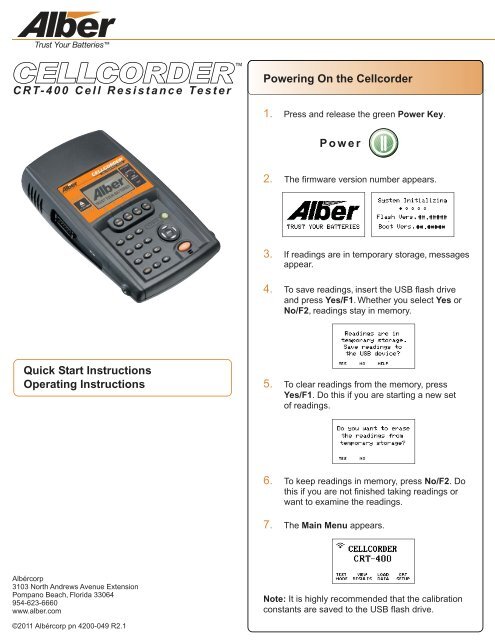
<strong>CRT</strong>-<strong>400</strong> Cell Resistance TesterPowering On the <strong>Cellcorder</strong>1. Press and release the green Power Key.Power2. The firmware version number appears.3. If readings are in temporary storage, messagesappear.4. To save readings, insert the USB flash driveand press Yes/F1. Whether you select Yes orNo/F2, readings stay in memory.<strong>Quick</strong> <strong>Start</strong> <strong>Instructions</strong>Operating <strong>Instructions</strong>5. To clear readings from the memory, pressYes/F1. Do this if you are starting a new setof readings.6. To keep readings in memory, press No/F2. Dothis if you are not finished taking readings orwant to examine the readings.7. The Main Menu appears.Albércorp3103 North Andrews Avenue ExtensionPompano Beach, Florida 33064954-623-6660www.alber.com©2011 Albércorp pn 4200-049 R2.1Note: It is highly recommended that the calibrationconstants are saved to the USB flash drive.
Powering Off the <strong>Cellcorder</strong>1. Press and hold the green Power Key. 2. Powering off doesn’t automatically deletevoltage or resistance readings from memory.Power3. If readings are in memory, you are promptedto save them.Taking Voltage Readings1. Connect the voltage probes to the <strong>Cellcorder</strong>and select Test Mode/F1.WarningDon't measure voltages greater than 20V DC.2. From the Test Mode menu, selectF1-Voltage.4. If "Stored in Memory" appears, retest thecell or change the cell number by typing anumber and pressing Enter.3. If "Resume Test" appears, put the probeson the cell.5. When the unit beeps, remove the probes.The cell number advances automaticallyto the next cell.
<strong>CRT</strong>-<strong>400</strong> Cell Resistance TesterThe <strong>Cellcorder</strong> is also a Digital Voltmeter (DVM)1. In the voltage mode, select DVM by pressingthe F1 button.2. The screen displays the measured voltages.3. Readings are not saved in DVM mode.Taking Resistance Radings1. Connect the resistance test leads to the<strong>Cellcorder</strong> and select Test Mode/F1.2. From the Test menu, select F2-Resistance.3. Select the Amp Hour rate/F2 of the cellbeing tested. Specify the number ofIntercell connections/F3 per cell.No VFloat Readings Exist.Now What?If "No VFloat readings exist. Are you sureyou want to continue?” appears. ChooseNo/F2, read voltage, then resume resistancetesting. Reading voltage before resistanceresults in more accurate voltage readingsbecause skewing is not a factor. If youchoose Yes/F1, voltage and resistance areread concurrently. Concurrent readings aresubject to the skewing effect.5. Connect the leads to the cell. See lower-leftfor some examples; refer to the <strong>CRT</strong>-<strong>400</strong> User’sGuide for more details. Press the orange Testbutton. The display shows test progress.4. Select Test/F1.VoltageInternal CellResistanceUp to 4Intercell Readings(mem) VoltageReadings Storedin Memory(act) ActualVoltage Reading6. When the unit beeps, remove the probes.When leads are moved, the cell numberadvances automatically to the next cell.7. When finished testing, press the Done/F4button.
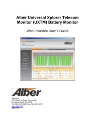
Connecting the Resistance LeadsThese figures show connectionsfor dual post cells.Take two readings.Read with the intercell leads connectedfrom terminal posts A to C.These figures show connectionsfor triple post cells.Take three readings.Read with the intercell leads connectedfrom terminal posts A to D.Then read with the intercell leads connectedfrom terminal posts B to D.REDReading 1REDREDRED/BLACKBLACKRED/BLACKBLACKReading 1RED/BLACKBLACKThen read with the intercell leadsconnnected from terminal posts B to E.Reading 2REDReading 2Take two readings.Read with the intercell leads connectedfrom terminal posts A to C.Then read with the intercell leadsconnected from terminal posts B to D.RED/BLACKBLACKRED/BLACKREDBLACKThen read with the intercell leadsconnnected from terminal posts C to F.REDREDReading 3Reading 1RED/BLACKBLACKReading 2RED/BLACKBLACK
Transferring Specific Gravityand Temperature ReadingsSaving the Readings1. On the <strong>CRT</strong>-<strong>400</strong>, select a cell data file totransfer Specific Gravity and Temperaturereadings into. This can be readings that alreadyexist in memory or you can open a previouslysaved set of readings from the USB flash drive.2. From the Main Menu, select Test Mode/F1.3. From the Test Mode menu, select F3-S.G./Temp.Saving New Data Readings to theUSB Flash Drive1. Make sure the <strong>Cellcorder</strong> has been chargedproperly.2. The USB flash drive may be placed into theleft side USB port on the <strong>Cellcorder</strong> before orafter the <strong>Cellcorder</strong> is powered on.3. Follow the prompts on the <strong>Cellcorder</strong>’s LCDaccordingly.4. When prompted to save readings to USBflash drive, select Yes/F1.4. From the SG/Temp screen, select Import bypressing F2.5. On the Data Module, select a channel (A-H)of data to transfer.5. Follow the prompts and enter the file nameand select Save/F2.6. If the file already exists, a Warningdisplays, asking for overwrite confirmation.Press F1 to overwrite the file or F2 to entera new file name.7. The USB flash drive has now stored thenew data.Note: Do not remove the USB flash drivewhile accessing data, writing to a file, readinginformation, etc.6. Align the Data Module and <strong>CRT</strong>-<strong>400</strong> IR port.7. On the <strong>CRT</strong>-<strong>400</strong> press F2 for Continue.8. When transfer is done, the S.G./Temp. valuefrom Cell 1 appears.WarningNever leave the USB flash drive pluggedinto the <strong>Cellcorder</strong> when performing tests orwhile the <strong>Cellcorder</strong> is connected to abattery for testing.Readings cleared from <strong>Cellcorder</strong>temporary storage cannot be retrievedunless they have been saved to the USBflash drive or PC.9. Select Import/F2 to save the file to theUSB flash drive.
Loading the ReadingsWireless Headset OperationLoading Data Readings from theUSB Flash Drive1. Insert a USB flash drive with readings intothe <strong>Cellcorder</strong>. From the Main Menu, selectF3-Load Data.2. Select F2-Cell Data.Using the Bluetooth ® Headset1. Make sure the <strong>CRT</strong> and the Bluetoothwireless headset are charged properly.2. Power the Bluetooth headset on.3. Power the <strong>CRT</strong> on. The <strong>CRT</strong> automaticallyattempts to connect to the last storedwireless device when powered on.4. To connect manually to a stored headset,select <strong>CRT</strong> Setup/F4 and use the downarrow key to go to F3-Bluetooth, press F3.3. Select-F2 the file from the list provided.Select FileSELECT DELETE BACK CANCELRecommended Steps to Save CAL-KThe CAL-K are calibration constants that areutilized for calibration correction during calibration.In the event these constants are lost, they can berestored easily.It is highly recommended that the calibrationconstants are saved to the USB flash drive.To save the constants:1. Make sure the <strong>CRT</strong> is powered on.2. Select Shift, then the number 7 from thekeypad.3. Enter the password ‘1234’ and press Enter.4. Select Calibration by pressing the number 1on the keypad.5. Choose CAL-K by selecting F2.6. Select F2 once again to confirm the Backup.7. Enter a File Name and select F2 to so Save.5. The last stored device will display, press F2to connect.6. When connecting to a new headset:a. Press F1-New.b. Now press F1-Headset.c. Place the Bluetooth device in discoverymode.d. Press F2 to Continue.e. When Bluetooth devices are found, a listis populated.Use the arrow keys to select the desiredBluetooth device and press F1.7. Once the Bluetooth headset and the <strong>CRT</strong>are connected, press F1-Test Mode.8. Choose the desired test by pressing eitherF1, F2, or F3.9. Place the Bluetooth headset on your ear fortest status information.The Bluetooth ® word mark and logos are registered trademarksowned by Bluetooth SIG, Inc and any use of such marks by <strong>Alber</strong> isunder license. Other trademarks and trade names are those of theirrespective owners.
Files Used by the <strong>CRT</strong>-<strong>400</strong> <strong>Cellcorder</strong> and Battery Analysis System (BAS) ProgramThere are many file types used with the <strong>Cellcorder</strong> and BAS program, and they are fully described in the user'sguides. This section describes the two most common file types..CDF Cell Data File -Created by the <strong>CRT</strong>-<strong>400</strong> when saving readings to the USB flash drive. It is the transport file that gets data fromthe <strong>CRT</strong>-<strong>400</strong> to the computer. This file contains one set or multiple sets (if in multi-string mode) of readings for acomplete string of batteries. The Battery Analysis System (BAS) program imports this file into an ADF file..ADF Accumulated Data File -Contains sets of readings that were imported from CDF files. One ADF file can contain many CDF files from thesame string. This gives the BAS program the ability to trend over many sets (different dates) of data. Create oneADF file for each string or one battery with parallel strings. Every time readings are taken for that string, importthe data in the CDF file into the ADF file.10/24/2011
Importing a CDF File into an ADF File1To import a CDF file into an ADF file:1. Select File then Open.32. In the Open dialog box at File Type, select<strong>Cellcorder</strong> Data File (*.cdf) from the drop-downlist.3. Navigate to the USB flash drive which isnormally labeled 'Removable Disk' under MyComputer.24. In the Confirmation dialog box, click Import toExisting File or Create New File. Both buttonsrefer to an ADF file.Note: If this is the first time importing, click CreateNew File and then, each time you take additionalreadings for that string, click Import to ExistingFile and select the appropriate previously-createdADF file.If Import to Existing File is selected, navigate to thedesired ADF file and select it. The new data will beadded to the existing data as a new read date whenviewing the readings.If Create New File is selected, the ConfigurationInformation dialog box appears. This box can beconfigured using the <strong>CRT</strong>-<strong>400</strong> template setup or withthe configurator in the program. You can change oradd information by using File then Properties.
<strong>CRT</strong>-<strong>400</strong> Cell Resistance TesterViewing Battery File PropertiesThis page describes the five File Properties pages, which you may use to edit battery data.Open a file, click File then Properties. You must click File then Save to save changes.The General page shows details and allows editing ofthese details, such as location name, battery name,number of strings, string name, battery model,temperature scale, installation date and number ofcells/jars. The temperature scale and number of cellswill affect the battery data file. The number of data sets,most recent read date, overall voltage, and averageresistance are also shown on the general page.Note: Do not use identical battery names in the samelocation name or identical string names in the samebattery name.The Details page displays a table of values for all cellswith data. Columns display cell number, cell voltage,internal resistance, intercell R1 to R4 resistance, specificgravity, and temperature. This list view can display celldata in colors based on threshold values, and intertiercell data in bold.10/24/2011The Intertier page manually or automatically markscells in a battery as intertier cells to indicate they are onthe boundary of an intertier connection. By convention,only the cell with the lower cell number is marked. Forexample, if Cell 10 is the last cell of one string andconnected to Cell 11, which is the first cell of the nextstring, only Cell 10 is marked as an intertier cell.The Comments page has a text editor for typingcomments, such as the date and type of readings takenor when connectors were cleaned. The Select a NewRead Date dialog box lets you associate comments witha read date. To save a Comments page as a template,click the Save As New Comment Template button.Use the User-Defined page to list reference notes.The notes, which can be included in reports, mightidentify pilot cells or equipment such as chargers.
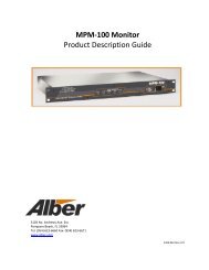
Viewing Battery ReadingsTo show a graph of an ADF Battery File: Click File then Open on the main menu and select a file name, thenclick Analysis, Data Set then Detail. To enlarge a graph area, drag a rectangle across it. To return to normalsize, right-click the graph and click Undo Zoom.View voltage, resistance, intercellresistance, temperature or SG.Set threshold display propertiesand the graph scale.View different data sets byselecting a date from the list.Print thegraph.Export to a file or theclipboard.10/11/2011Shows the minimum, maximum andaverage values of the readings.Bar Graph Cell DataTo display text data for a cell, click on a bar. The Cell Data box showsCell Number, Cell Voltage, Internal Resistance, IntercellResistance, Specific Gravity and Temperature when available.
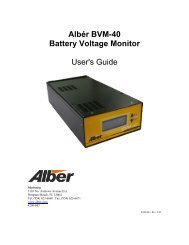
Trending a Parameter Over TimeTrending a specific parameter can help identify aproblem:1. Open a file with at least two data sets and click theView Battery Data Set Graphs button.10/24/2011 12:58, 685.2352. Click a cell in the graph, then clickParameters, Trend then Cells.3. Click the Select Which Parameters Appear inGraph button.4. On the Data Subsets box, select InternalResistance only. A Battery Cell Trend Graphdisplays the cell values over time.5. Click a data point or date to display details in theCell Data box. If the box does not appear, enableit under File then Preferences.2009 2010201110/24/201110/24/2011Trending a Parameter Average Over TimeTrending a parameter average helps identify inconsistencies in a battery system, and trending internalresistance averages helps determine a battery's end of life. The average summaries on the internal resistancescreen are calculated to reduce false averages. The calculation eliminates cells above or below the true averageby 25%, and then recalculates a new Modified Average.1. Open a file with at least two Data Sets and clickthe View Battery Data Set Graphs button.2. Click a cell in the graph, then clickParameters, Trend then Cell Averages.10/24/2011 12:58, 685.2353. Click the Select Which Parameters Appear inGraph button.4. On the Data Subsets box, select InternalResistance only. A Battery Cell Averages TrendGraph displays internal resistance over time.5. Click a data point or date to display details in theCell Data box.20092010 201110/24/201110/24/2011
Generating ReportsThe BAS Report Generator creates five reports: a Detail, Comparison, Threshold Deviation, Cell Trend, andCell Average Trend Report with lists, graphs or both.Click Create Report after setup. View saved reports using the Archive Reader. Buttons on report pages changeview size, print, and save as a ZRF archive file. To save the text portion as a text file, select TXT in the Save AsType field.Data Set DetailThis report creates lists and graphs of selectedData Sets. Clicking Reports, Data Set then Detailopens five setup pages: Data Sets selects sets ofreadings to include. Strings/Cells identifies cellrange. Graphs and Tables includes tabular orgraph information. User Defined defines userfields and comments. Other Options offers title,date, time, page number, size and footer.Data Set Comparison ReportThis report compares selected data setsreferenced to one data set.Click Reports, Data Set then Comparison. All dataset dates except the reference can be in one report.Cell Trend ReportThis report creates a tabular list of selecteddata sets with respect to time.Click Reports, Trend then Cells.Cell Average Trend ReportThis report creates a tabular list of selected datasets averages with respect to time.Click Reports, Trend then Cell Averages.10/24/2011Threshold Deviation ReportThe Data Set Threshold Report creates a listthat shows threshold violations of selected datasets.10/24/2011Archive ReaderThe Archive Reader displays and prints reportsthat were generated and saved with the ReportGenerator. To start the reader:Click Reports then Load and open a report file.You may open a previously saved report any timethe Archive Reader is on screen. The reader opens<strong>CRT</strong>-<strong>400</strong> ZRF report files and may be downloadedfrom the Albér Web site: www.alber.com.