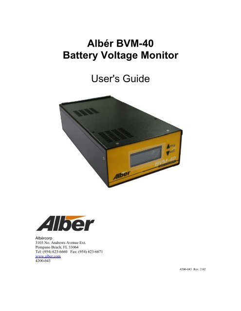
Albér BVM-40 Battery Voltage Monitor User's Guide - Alber
Albér BVM-40 Battery Voltage Monitor User's Guide - Alber
Albér BVM-40 Battery Voltage Monitor User's Guide - Alber
- No tags were found...
You also want an ePaper? Increase the reach of your titles
YUMPU automatically turns print PDFs into web optimized ePapers that Google loves.
Albér <strong>BVM</strong>-<strong>40</strong><strong>Battery</strong> <strong>Voltage</strong> <strong>Monitor</strong><strong>User's</strong> <strong>Guide</strong>Albércorp3103 No. Andrews Avenue Ext.Pompano Beach, FL 33064Tel: (954) 623-6660 Fax: (954) 623-6671www.alber.com4200-0434200-043 Rev. 2.02
Copyright and Disclaimer<strong>Battery</strong> <strong>Voltage</strong> <strong>Monitor</strong> (<strong>BVM</strong>-<strong>40</strong>) User’s <strong>Guide</strong>Document Revision 2.02Release Date 02/22/2012Part Number 4200-043Revision HistoryRevision Date of Change Description of Change By2.01 05/05/06 Initial Release LL2.02 02/22/12 Made engineering updates for alarm wires, alarmcontacts and alarm relays. Updated and addeddrawings in the back of this guideMSAlbér <strong>Battery</strong> <strong>Voltage</strong> <strong>Monitor</strong> (<strong>BVM</strong>‐<strong>40</strong>) User <strong>Guide</strong>, Part Number 4200‐043©2012 Albércorp. All rights reserved.Albércorp, 3103 North Andrews Avenue Extension, Pompano Beach FL 33064.No part of this document may be reproduced or transmitted in any form or by any means, electronic or mechanical,including photocopying and recording for any purpose, without the express written permission of Albércorp.Information in this document is subject to change without notice.TrademarksThe first instances of registered trademarks or trademarks of Albércorp and other companies are annotated aboveusing the ® and symbols. For ease of reading, these symbols do not appear in the remainder of this document.Printed in the United States of America.i4200–043 Revision 2.02
Albér Customer ServiceAlbér Customer Service is available Monday to Friday, 8:00AM to 4:30PM Eastern Time.Telephone: (954) 623-6660Fax: (954) 623-6671Email: service@alber.comWebsite: www.alber.comCorporate Office Address:Albércorp3103 North Andrews Avenue Ext.Pompano Beach, FL 33064 USA4200–043 ii Revision 2.02
SOFTWARE LICENSE AGREEMENTREAD THESE TERMS AND CONDITIONS CAREFULLY BEFORE ATTEMPTING TODOWNLOAD, INSTALL, OR USE THE SOFTWARE. BY DOWNLOADING, INSTALLING, ORUSING THE SOFTWARE, YOU AGREE TO BE BOUND BY THESE TERMS AND CONDITIONS.IF YOU DO NOT ACCEPT THESE TERMS AND CONDITIONS, DO NOT DOWNLOAD,INSTALL, OR USE THE SOFTWARE. IN SUCH A CIRCUMSTANCE, THE SOFTWARE MAYBE RETURNED WITHIN THIRTY (30) DAYS OF YOUR RECEIPT FOR A FULL SOFTWAREREFUND. YOU REPRESENT THAT YOU (I) ARE NOT LOCATED IN, UNDER THE CONTROLOF, OR A NATIONAL RESIDENT OF ANY COUNTRY TO WHICH THE UNITED STATES HASEMBARGOED GOODS, (II) ARE NOT ON THE U.S. TREASURY DEPARTMENT'S LIST OFSPECIALLY DESIGNATED NATIONALS, (III) ARE NOT ON THEU.S. COMMERCE DEPARTMENT'S LIST OF DENIED PERSONS, OR (IV) ARE NOTOTHERWISE PROHIBITED BY U.S. LAW FROM RECEIVING OR USING THE SOFTWARE(COLLECTIVELY “EXPORT RESTRICTIONS”). IF YOU DO NOT HAVE AUTHORITY TOACCEPT THIS AGREEMENT FOR YOUR ORGANIZATION, IT IS YOUR OBLIGATION TOENSURE THAT AN AUTHORIZED INDIVIDUAL MAKES THE DETERMINATION THAT YOURORGANIZATION IS NOT SUBJECT TO THE ABOVE EXPORT RESTRICTIONS PRIOR TODOWNLOADING, INSTALLING, OR USING THE SOFTWARE.This Software License Agreement (“Agreement”) is a legal agreement between you and Albér Corp., aFlorida, United States of America, corporation, (“Albér”). Albér's software, including enhancements,upgrades, and any future releases, if provided, is made available exclusively for use with the associatedAlbér products (the “Products”). The foregoing, including any accompanying program(s), documentation,images, animation, and text incorporated therein, (collectively “Software”), is provided solely forcommercial and industrial use under the license terms specified herein.GRANT OF RIGHTS: Provided that you comply with all of the terms of this Agreement, Albér grants anon-exclusive, non-transferable license to you to install and use the Software solely for use with Products asprovided for herein. You represent and warrant that you will not use the Software in violation of applicablelaws and regulations or where such use detrimentally affects Albér’s rights in the Software or subjects Albérto liability. You assume responsibility for the selection of the Software to achieve your intended results, andfor the installation, use, and the results obtained from the Software. Provided that you have paid theapplicable license fees, you may use (i) BMDM with SQL, on one server on one site, with a maximum oftwo hundred (200) users; (ii) all other Software, an unlimited number users per site. Any other operation ofthe Software at any time shall constitute a material breach of this Agreement and shall terminate this licenseas provided for below. By use of the Software, you agree that Albér may, at its option, perform an audit ofyour usage of the Software to determine the number of servers and Products that are using the Software.TERMINATION OF LICENSE: Your license is automatically terminated if you: (1) use the Software withanything other than Products, (2) attempt to copy or reconstruct any part of the object code, source code, oralgorithms, (3) attempt to decompile, disassemble or reverse engineer the Software, in whole or in part, orotherwise attempt to derive the source code of the Software, (4) provide, disclose, sell, rent, lease, license,sublicense, or otherwise transfer or assign the Software to any third party, (5) use the Software in excess ofthe licensed coverage purchased, (6) write or develop any derivative software or any other software programbased upon the Software, (7) modify or alter the Software, or (8) fail to comply with any other license terms.You may elect to terminate this license at any time by destroying the Software together with all copies andany portions thereof in any form.LIMITED WARRANTY: Albér represents that it has the right and authority to grant the license herein.Albér warrants solely to you for a period of thirty (30) days from the date of Albér shipment or distributionthat the distribution media (if supplied) on which the Software is furnished under normal use will be freefrom defects in material and workmanship and the Software will substantially conform to Albér publishediii4200–043 Revision 2.02
documentation. EXCEPT FOR THE ABOVE EXPRESS WARRANTIES, THIS SOFTWARE ISPROVIDED "AS IS" WITHOUT WARRANTY OF ANY KIND, EXPRESS OR IMPLIED, INCLUDING,WITHOUT LIMITATION, IMPLIED WARRANTIES OF MERCHANTABILITY OR FITNESS FORINTENDED PURPOSE. ALBÉR DOES NOT WARRANT THAT THE SOFTWARE FUNCTIONS WILLMEET YOUR REQUIREMENTS OR THAT THE SOFTWARE WILL OPERATE UNINTERRUPTED ORERROR FREE.LIMITATION OF REMEDIES: Albér's entire liability and your exclusive remedy arising from use orinability to use the Software is:(1) The replacement of any distribution media not meeting Albér's warranty,or (2) If Albér is unable to provide you a replacement that conforms to Albér's warranty, to refund thepurchase price. THE REMEDIES SET FORTH IN THIS AGREEMENT ARE EXCLUSIVE.LIMITATION OF DAMAGES: IN NO EVENT, REGARDLESS OF THE FORM OF THE CLAIMOR CAUSE OF ACTION (WHETHER BASED IN CONTRACT, INFRINGEMENT,NEGLIGENCE,STRICT LIABILITY, OTHER TORT, OR OTHERWISE), SHALL ALBÉR’S LIABILITY TO YOUEXCEED THE PRICE PAID BY YOU FOR THE SOFTWARE. YOU AGREE THAT ALBÉR’SLIABILITY TO YOU SHALL NOT EXTEND TO INCLUDE SPECIAL, INCIDENTAL,CONSEQUENTIAL, OR PUNITIVE DAMAGES EVEN IF ALBÉR IS ADVISED OF THEPOSSIBILITY OF THESE DAMAGES. The term "consequential damages" shall include, but not belimited to, loss of anticipated profits, business interruption, loss of use, revenue, reputation and data, costsincurred, including without limitation, for capital, fuel, power and loss or damage to property or equipment.You acknowledge that this Agreement reflects this allocation of risk.COPYRIGHT: This Software is the proprietary property of Albér and/or its suppliers and is protected byUnited States copyright laws, other applicable copyright laws, and international treaty provisions. Title andownership of all copyrights to the Software remain in Albér or third parties. Accordingly, your rights to use,copy and modify the Software are strictly limited to the specific rights provided in this Agreement or as mayotherwise be required by applicable copyright law.U.S. GOVERNMENT RESTRICTED RIGHTS: This Software is developed at private expense and isprovided with "Restricted Rights." Use, duplication, or disclosure by the United States Government issubject to restrictions set forth in the Federal Acquisition Regulations and its Supplements.ASSIGNMENT: You may not sublicense, assign, or otherwise transfer this license of the Software withoutthe prior written consent of Albér. Any such transfer of rights, duties, or obligations is void and terminatesthis Agreement.EXPORT RESTRICTIONS: You may not export the Software in violation of applicable export laws andregulations of the applicable countries. You agree to comply with all laws, regulations, decrees and ordersof the United States of America that restrict the exportation (or re-exportation) of the Software to othercountries, including, without limitation, the U.S. Export Administration Regulations.UPDATE POLICY: Albér may create, from time to time, updated versions of the Software. Albér reservesthe right to make changes to or improvements in any aspect of the Software at any time without prior noticeto you and without an obligation to supply such changed and/or improved Software to you.NUCLEAR/MEDICAL: THE SOFTWARE IS NOT FOR USE IN CONNECTION WITH ANYNUCLEAR, MEDICAL, LIFE-SUPPORT, AND RELATED APPLICATIONS. You agree to defend,indemnify, and hold harmless Albér from any claims, losses, suits, judgments and damages, includingincidental and consequential damages, arising from such use, whether the cause of action be based in tort,contract or otherwise, including allegations that the Albér’s liability is based on negligence or strict liability.JAVA SUPPORT: The Software may contain support for programs written in Java. Java Technology is notfault tolerant and is not designed, manufactured, or intended for use or resale as online control equipment inhazardous environments requiring fail-safe performance, such as in the operation of nuclear4200–043 iv Revision 2.02
facilities, aircraft navigation or communication systems, air traffic control, direct life support machines, orweapons systems, in which the failure of java technology could lead directly to death, personal injury, orsevere physical or environmental damage.COMPLETE AGREEMENT/GOVERNING LAW/VENUE: This Software license agreement comprisesthe final and complete agreement between the parties. No person is authorized to change or modify thisAgreement except an executive officer of Albér Corporation and then only in writing. The laws of the UnitedStates and the State of Florida shall apply to this Agreement and its interpretation without reference to choiceor conflict of laws principles. Albér and you hereby irrevocably submit to the personal and subject matterjurisdiction of any State of Florida or federal court sitting in Miami, Florida, in any action or proceedingarising from or relating to this Agreement. If any provision of this Agreement is held to be void, invalid,unenforceable, or illegal, the other provisions shall continue in full force and effect.v4200–043 Revision 2.02
LIMITED WARRANTY FOR ALBÉR PRODUCTSThis Warranty is given ONLY to purchasers who buy for commercial or industrial use in the ordinary course of each purchaser'sbusiness.General:Albér Corp. products and systems are, in our opinion, the finest available. We take pride in our products and are pleased that you havechosen them. Under certain circumstances, we offer with our products the following One Year Warranty Against Defects in Materialand Workmanship.Please read your Warranty carefully. This Warranty sets forth our responsibilities in the unlikely event of defect and tells you how toobtain performance under this Warranty.ALBÉR PRODUCTS COVERED:ONE YEAR LIMITED WARRANTYAGAINST DEFECTS IN MATERIAL AND WORKMANSHIPBDS-<strong>40</strong>, BDS 256XL, BDSU, <strong>BVM</strong>-<strong>40</strong>, MPM-100, and UXTM.Terms of Warranty:As provided herein, the Albér product is warranted to be free of defects in material and workmanship for a period of twelve (12)months from date of commissioning, not to exceed eighteen (18) months from date of shipment, provided that startup is performed byAlbér authorized personnel, and the product has been stored in a suitable environment prior to start-up. The start-up date will bedetermined only from the completed ASCOMP file provided to Albér from User and accepted by Albér. The product shipment datewill be determined only from the Albér bill of lading. If any part or portion of the Albér product fails to conform to theWarranty within the Warranty period, Albér, at its option, will furnish new or factory remanufactured products for repair orreplacement of that portion or part.Warranty Extends to First Purchaser for Use. Non-transferable:This Warranty is extended to the first person, firm, association or corporation for whom the Albér product specified herein isoriginally installed for use (the "User"). This Warranty is not transferable or assignable without the prior written permission of Albér.Assignment of Warranties:Albér assigns to User any warranties which are made by manufacturers and suppliers of components of, or accessories to, the Albérproduct and which are assignable, but Albér makes NO REPRESENTATIONS as to the effectiveness or extent of such warranties,assumes NO RESPONSIBILITY for any matters which may be warranted by such manufacturers or suppliers and extends nocoverage under this Warranty to such components or accessories.Drawings. Descriptions:Albér warrants for the period and on the terms of the Warranty set forth herein that the Albér product will conform to thedescriptions contained in the approved drawings, if any, applicable thereto, to Albér's final invoices, and to applicable Albér productbrochures and manuals current as of the date of product shipment ("Descriptions"). Albér does not control the use of any Albérproduct. Accordingly, it is understood that the Descriptions are NOT WARRANTIES OF PERFORMANCE and NOTWARRANTIES OF FITNESS FOR A PARTICULAR PURPOSE.Warranty Claims Procedure:Within a reasonable time, but in no case to exceed thirty (30) days after <strong>User's</strong> discovery of a defect, User shall contact Albér at 1-800-851-4632.User shall ship the product, with proof of purchase, to Albér freight prepaid. Albér products shipped to Albér without a returnauthorization number will be refused and returned freight collect to User at <strong>User's</strong> expense. Products shipped by User to Albér whichhave incurred freight damage due to <strong>User's</strong> improper packaging of the product will not be covered by this Warranty and anyreplacement parts, components or products needed will be invoiced in the full current price amount and returned freight collect toUser.Subject to the limitations specified herein, Albér will replace, without charge for Albér labor or materials, subsequent to its inspection,and return freight prepaid F.O.B. Albér's facility, the product shipped to Albér with a return authorization number and warrantedhereunder which does not conform to this Warranty.Warranty coverage will be applicable only after Albér's inspection discloses the claimed defect and shows no signs of treatment or usethat would void the coverage of this Warranty. All defective products and component parts replaced under this warranty become theproperty of Albér.Warranty Performance of Component Manufacturers:4200–043 vi Revision 2.02
It is Albér's practice, consistent with its desire to remedy Warranty defects in the most prompt and effective manner possible, tocooperate with and utilize the services of component manufacturers and their authorized representatives in the performance of workto correct defects in the product components. Accordingly, Albér may utilize third parties in the performance of Warranty work,including repair or replacement hereunder, where, in Albér's opinion, such work can be performed in less time, with less expense, orin closer proximity to the Albér product.Items Not Covered By Warranty:THIS WARRANTY DOES NOT COVER DAMAGE OR DEFECT CAUSED BY misuse, improper application, wrong or inadequateelectrical current or connection, negligence, inappropriate on site operating conditions, repair by non-Albér designated personnel,accident in transit, tampering, alterations, a change in location or operating use, exposure to the elements, Acts of God, theft orinstallation contrary to Albér's recommendations or specifications, or in any event if the Albér serial number has been altered,defaced, or removed.THIS WARRANTY DOES NOT COVER shipping costs, installation costs, or maintenance or service items and further, except asmay be provided herein, does NOT include labor costs or transportation charges arising from the replacement of the Albér productor any part thereof or charges to remove or reinstall same at any premises of User.REPAIR OR REPLACEMENT OF A DEFECTIVE PRODUCT OR PART THEREOF DOES NOT EXTEND THE ORIGINALWARRANTY PERIOD.Limitations:• THIS WARRANTY IS IN LIEU OF AND EXCLUDES ALL OTHER WARRANTIES, EXPRESS OR IMPLIED,INCLUDING MERCHANTABILITY AND FITNESS FOR A PARTICULAR PURPOSE.• USER'S SOLE AND EXCLUSIVE REMEDY IS REPAIR OR REPLACEMENT OF THE ALBÉR PRODUCT AS SETFORTH HEREIN.• IF USER'S REMEDY IS DEEMED TO FAIL OF ITS ESSENTIAL PURPOSE BY A COURT OF COMPETENTJURISDICTION, ALBÉR'S RESPONSIBILITY FOR PROPERTY LOSS OR DAMAGE SHALL NOT EXCEED THENET PRODUCT PURCHASE PRICE.• IN NO EVENT SHALL ALBÉR ASSUME ANY LIABILITY FOR INDIRECT, SPECIAL, INCIDENTAL,CONSEQUENTIAL OR EXEMPLARY DAMAGES OF ANY KIND WHATSOEVER, INCLUDING WITHOUTLIMITATION LOST PROFITS, BUSINESS INTERRUPTION OR LOSS OF DATA, WHETHER ANY CLAIM ISBASED UPON THEORIES OF CONTRACT, NEGLIGENCE, STRICT LIABILITY, TORT, OR OTHERWISE.Miscellaneous:• NO SALESPERSON, EMPLOYEE OR AGENT OF ALBÉR IS AUTHORIZED TO ADD TO OR VARY THE TERMS OFTHIS WARRANTY. Warranty terms may be modified, if at all, only by a writing signed by a Albér officer.• Albér obligations under this Warranty are conditioned upon Albér timely receipt of full payment of the product purchaseprice and any other amounts due. During the period when any amounts are overdue from User, Albér warranty obligationsshall be suspended. The warranty expiration date shall not be extended upon payment of the overdue amount. Albér reservesthe right to supplement or change the terms of this Warranty in any subsequent warranty offering to User or others.• In the event that any provision of this Warranty should be or becomes invalid and/or unenforceable during the warrantyperiod, the remaining terms and provisions shall continue in full force and effect.• This Warranty shall be governed by, and construed under, the laws of the State of Florida, without reference to the conflictof laws principles thereof.• This Warranty represents the entire agreement between Albér and User with respect to the subject matter herein andsupersedes all prior or contemporaneous oral or written communications, representations, understandings or agreementsrelating to this subject.vii4200–043 Revision 2.02
Table of Contents1. SAFETY INFORMATION ............................................................................................................................ 11.1. If You Have Questions ................................................................................................................... 12. SYSTEM REQUIREMENTS ......................................................................................................................... 22.1. Components .................................................................................................................................... 22.2. Wiring ............................................................................................................................................. 22.3. Disconnect Device .......................................................................................................................... 32.4. Ventilation ...................................................................................................................................... 33. GENERAL DESCRIPTION .......................................................................................................................... 43.1. Definitions ...................................................................................................................................... 44. PANEL CONTROLS AND INDICATORS ....................................................................................................... 54.1. Symbols .......................................................................................................................................... 55. INSTALLING THE <strong>BVM</strong> ............................................................................................................................ 65.1. Mounting the <strong>BVM</strong> ........................................................................................................................ 65.2. <strong>Voltage</strong> Sense Lead Harness Routing ............................................................................................. 75.3. <strong>Voltage</strong> Sense Lead Connections ................................................................................................... 75.4. Alarm Relay Contact Connections ................................................................................................. 76. USING THE <strong>BVM</strong> ..................................................................................................................................... 86.1. Viewing the Setup Menu ................................................................................................................ 86.2. Setting the Total Jar Number .......................................................................................................... 96.3. Viewing Jar <strong>Voltage</strong>s ...................................................................................................................... 96.4. Viewing High Jar <strong>Voltage</strong>s ........................................................................................................... 106.5. Viewing Low Jar <strong>Voltage</strong>s ........................................................................................................... 107. CALIBRATING THE <strong>BVM</strong> ....................................................................................................................... 117.1. Selecting the Calibration Option .................................................................................................. 118. PREVENTIVE MAINTENANCE ................................................................................................................. 129. <strong>BVM</strong>-<strong>40</strong> SPECIFICATIONS ..................................................................................................................... 13OPERATING ENVIRONMENT ........................................................................................................................ 1310. <strong>BVM</strong>-<strong>40</strong> PARTS LIST ........................................................................................................................ 1411. <strong>BVM</strong>-<strong>40</strong> DRAWINGS ......................................................................................................................... 1512. INDEX ................................................................................................................................................ 244200–043 viii Revision 2.02
List of FiguresFigure 1. Version Number Screen .................................................................................................................. 8Figure 2. Summary Screen ............................................................................................................................. 8Figure 3. Setup Menu Screen ......................................................................................................................... 8Figure 4. Total Jars Screen ............................................................................................................................. 9Figure 5. Jar <strong>Voltage</strong> Screen........................................................................................................................... 9Figure 6. Jar High <strong>Voltage</strong> Alarm Screen .................................................................................................... 10Figure 7. Jar Low <strong>Voltage</strong> Alarm Screen ..................................................................................................... 10Figure 8. Calibration Screen ......................................................................................................................... 11Figure 9. General Assembly ......................................................................................................................... 15Figure 10. Cabinet Mounting........................................................................................................................ 16Figure 11. Wiring Schematic ........................................................................................................................ 17Figure 12. Flex Resistor Lead Assembly ...................................................................................................... 18Figure 13. Sense Lead Connection Options ................................................................................................. 19Figure 14. Sense Lead Harness for 1 through 15 .......................................................................................... 20Figure 15. Sense Lead Harness for 16 through 24 ........................................................................................ 21Figure 16. Sense Lead Harness for 25 through <strong>40</strong> ........................................................................................ 22Figure 17. Cabinet Mounting Dimensions .................................................................................................... 23IMPORTANT NOTE: The following drawings are required for the <strong>BVM</strong>-<strong>40</strong>. The drawings inthis manual may not be of the latest revision and are included for reference only. Refer to theEngineering Drawing Package included with your system for drawings with the latest revisions.General Assembly, <strong>BVM</strong>-<strong>40</strong> .................................................................................................. BDS-362-B945General Assembly, Cabinet Mounting, <strong>BVM</strong>-<strong>40</strong> ................................................................... BDS-363-A572Wiring Schematic, <strong>BVM</strong>-<strong>40</strong> to <strong>40</strong> 12V Module <strong>Battery</strong> ...................................................... BDS-2268-B946Fabrication Detail, Flex Resistor Lead Assembly, BDS/<strong>BVM</strong> <strong>Monitor</strong>s ............................. BDS-1226-A609Installation Details, Sense Lead Connection Options, <strong>BVM</strong>-<strong>40</strong> .......................................... BDS-1165-A568Subassembly, Module 1 - 15, Sense Lead Harness, <strong>BVM</strong>-<strong>40</strong> .............................................. BDS-1166-A569Subassembly, Module 16 - 24, Sense Lead Harness, <strong>BVM</strong>-<strong>40</strong> ............................................ BDS-1167-A570Subassembly, Module 25 - <strong>40</strong>, Sense Lead Harness, <strong>BVM</strong>-<strong>40</strong> ........................................... BDS-1168- A571Cabinet Mounting Dimensions Template, <strong>BVM</strong>-<strong>40</strong> ....................................................................................... -ix4200–043 Revision 2.02
System Requirements2. System RequirementsThe following are requirements for a typical <strong>BVM</strong>-<strong>40</strong> system.2.1. Components<strong>Alber</strong> <strong>BVM</strong>-<strong>40</strong> <strong>Battery</strong> <strong>Voltage</strong> <strong>Monitor</strong>.<strong>Voltage</strong> sense leads.<strong>Alber</strong> <strong>BVM</strong>-<strong>40</strong> <strong>Battery</strong> <strong>Voltage</strong> <strong>Monitor</strong> <strong>User's</strong> <strong>Guide</strong>, 4200-043 (this manual).Wiring diagrams for <strong>BVM</strong> to jar connection (as required).Tools for installing cabling and connecting the <strong>BVM</strong> to the jars.2.2. WiringThe <strong>BVM</strong>-<strong>40</strong> is designed to connect to jars that have a nominal voltage of 12VDC.The receptacle for the AC cord from the <strong>BVM</strong>-<strong>40</strong> must have protective earth connection(three prong). Do not defeat the use of the earth connection prong.The alarm relay contact connections are for the user to monitor high or low system cellvoltages, alarm contacts will indicate higher or lower cell voltage on the harness. Theseconnections are used for accessing the three connections on the Mux board (P2) to the alarmcontacts.Alarm contacts on P2 on mux board 1101-677D exist on the following three connections: Pin 11 (common) (C) Pin 12 Normally Closed (NC) Pin 13 Normally Open (NO)(for modified on units only Model number that were created in 2012????Important: before 2012 the low and high cell voltage alarm modification was not available.Note: the board number 1101-675A which is a display board must have the new firmware forthe alarm contacts.Refer to the back of this guide for diagrams of the sub assembly of module 1 though 15 and16 through 24 sense lead harness.Drawings in this manual may be for reference only or superseded by later drawings. For thelatest information, refer to the drawings supplied with your system in this document.4200–043 2 Revision 2.02
System Requirements2.3. Disconnect DeviceThe three prong AC cord from the cabinet, which connects to the 115VAC receptacle, isconsidered the primary disconnect device.2.4. VentilationYou must provide adequate ventilation to prevent equipment overheating. Only the top of the<strong>BVM</strong> has ventilation holes. If mounting the <strong>BVM</strong> from the top, use the standoffs provided toensure adequate ventilation. Do not block the ventilation ports, and ensure the equipment isoperated within the temperature and humidity ranges described in this manual.4200–043 3 Revision 2.02
System Requirements3. General DescriptionThe Albér <strong>BVM</strong>-<strong>40</strong> <strong>Battery</strong> <strong>Voltage</strong> <strong>Monitor</strong> helps ensure that jars used in battery backupsystems will perform when needed. The <strong>BVM</strong> continually reads the voltages of up to <strong>40</strong> jars thateach have a nominal voltage of 12VDC. An easily readable, backlit LCD (liquid crystal display)screen indicates each jar voltage, minimum, maximum and average jar voltage, and overall stringvoltage.Two front panel push buttons are used to light the LCD screen, view readings, set up the unit, andcalibrate the unit when necessary. The buttons are either pressed independently or together toenable the various functions. The light on the LCD goes off after about one minute. Pressing theup or down button turns the light back on.To alarm the user for high or low system cell voltages, alarm contacts will indicate higher orlower cell voltage on the harness for accessing the three connections on the Mux board (P2) to thealarm contacts.The power switch is on the rear panel. The <strong>BVM</strong> may be left powered on continuously with noadverse effects.3.1. DefinitionsJar – The container that holds a cell or group of cells. In this manual, the term jar refers toone 12 volt battery consisting of six cells.Cell – The basic electrochemical unit that delivers electrical energy. Common usage permitsthe use of the word battery when referring to a cell, although it is technically incorrect. Thenominal voltage of a cell is 2 volts.<strong>Battery</strong> – Two or more cells (or jars) connected together electrically.4200–043 4 Revision 2.02
Panel Controls and Indicators4. Panel Controls and IndicatorsThis section describes the front and rear panels of the <strong>BVM</strong>-<strong>40</strong>. Additional descriptions mayappear elsewhere in this manual or related manuals.Front Panel IndicatorsLCD display screen ................... Displays all functions, including jar voltage, string voltage,setup, and calibration.Front Panel ConnectorsNone.Front Panel ControlsJar Select switches ..................... Two up/down push button switches for illuminating the LCDdisplay, stepping through readings, selecting screens and menuitems, and setting parameters.Rear Panel IndicatorsNone.Rear Panel ConnectorsDB-37 ........................................ Four DB-37 connectors for connecting the <strong>BVM</strong> to <strong>40</strong> jars orless for voltage monitoring.AC Power .................................. AC power cord receptacle with user-replaceable fuse.<strong>BVM</strong> Rear Panel ControlsPower switch ............................. Rocker switch for <strong>BVM</strong> AC power on and off.4.1. Symbols!This symbol, which may appear on equipment panels and cabinets, indicates:CAUTION. Refer to accompanying documents. Be sure to read and understand thedocuments that relate to the particular unit. If you do not understand the documentation, stopand contact Albér or an authorized Albér representative.4200–043 5 Revision 2.02
Installing the <strong>BVM</strong>5. Installing the <strong>BVM</strong>This section describes how to mount the <strong>BVM</strong>, install the voltage sense leads, and terminate thewires at the <strong>BVM</strong> and jar ends. The <strong>BVM</strong>-<strong>40</strong> system consists of the <strong>BVM</strong>-<strong>40</strong> unit and cables thatconnect the unit to the jars being monitored. Refer to the system drawings and verify allcomponents are available before starting installation.WARNING: Do not energize the <strong>BVM</strong> or any component with 115VAC or battery voltage untilafter the installation is complete.The maximum length for each voltage sense lead is 100 feet (30.5 meters) from <strong>BVM</strong> to jar.Consider this length and locate the <strong>BVM</strong> reasonably close to the jars (batteries). Mount the <strong>BVM</strong>to allow for front and rear panel access. You will need the following tools (or equivalents) tomount and connect the <strong>BVM</strong>:Panduit CT-260 crimper for terminals.Flat blade and Phillips screwdrivers for <strong>BVM</strong> connectors and mounting hardware.Drill and 7/32" (0.218") drill bit.5.1. Mounting the <strong>BVM</strong>Normally, mount the <strong>BVM</strong> directly to the outside top or inside top of the battery cabinet.Four threaded mounting holes on the <strong>BVM</strong> top and bottom allow mounting from either side.Refer to drawing BDS-363-A572 for typical installation.If you are securing the <strong>BVM</strong> to the inside top of the cabinet, use the four standoffs providedto ensure adequate ventilation through the top cover. A template drawing (included) identifieswhere to drill the holes in the battery cabinet. Using the template, drill the holes using a 7/32"(0.218") drill bit, remove any burrs from the drilled holes, and mount the unit with thesupplied screws (and standoffs if required).WARNING: The four mounting screws must not hit the internal components in the <strong>BVM</strong>-<strong>40</strong>.Do not substitute the four screws supplied (#10-32x3/8"). The screws must not go more than3/8" into the unit. The supplied screws will provide sufficient holding strength for mountingthe <strong>BVM</strong>-<strong>40</strong> to surfaces up to 1/8" thick.After mounting, ensure the ventilation holes on the top of the <strong>BVM</strong> are not blocked.4200–043 6 Revision 2.02
Installing the <strong>BVM</strong>5.2. <strong>Voltage</strong> Sense Lead Harness RoutingThe installer normally determines the wire routing. If the <strong>BVM</strong> is not located directly on or inthe battery cabinet, do not route the wires in the same conduit as other wires in the facility.Use a Panduit (or equivalent) insulated, slotted cable tray with cover to distribute wires to thejars. Suggested cable trays and covers are Panduit E1X1L66 with C1L66, or E5X5L66 withC5L66. When installing the tray along the length of each battery tier, make sure the tray doesnot interfere with jar replacement and the jars remain accessible for servicing afterinstallation.If the <strong>BVM</strong> is located on or in the battery cabinet, a cable tray is not needed. Neatly tie wrapthe wires in bundles, with appropriate service lengths available.5.3. <strong>Voltage</strong> Sense Lead ConnectionsThe supplied wiring harness is for batteries with up to <strong>40</strong> jars. Some batteries will have fewerthan <strong>40</strong> jars, and all the sense leads will not be needed. In this case, you should remove anddiscard the extra leads (see below).Route each sense lead from the <strong>BVM</strong> to the jar and cut to length. Before connecting to thejar, install a tab washer or "C" clamp on the battery for making connection; refer to drawingBDS-1165-A568 for details. Also, you must install a current limiting resistor (supplied) at theend of each lead nearest the battery; refer to BDS-120-A373. Use drawing BDS-2268-B946for identifying harness assemblies and locating sense leads.If the battery has fewer than <strong>40</strong> jars, connect the lead that would normally connect to thepositive post of the next jar to the negative post of the last jar. For example, if the battery has32 jars, connect the lead that normally connects to jar 33 positive to the negative post of jar32. Albér recommends you remove the connector cover and cut off and discard any unusedharness leads.5.4. Alarm Relay Contact ConnectionsThe alarm relay contact connections are for the user to monitor high or low system cell voltages,alarm contacts will indicate higher or lower cell voltage on the harness. These connections areused for accessing the three connections on the Mux board (P2) to the alarm contacts.Alarm contacts on P2 on mux board 1101-677D exist on the following three connections: Pin 11 (common) (C) Pin 12 Normally Closed (NC) Pin 13 Normally Open (NO)7
Using the <strong>BVM</strong>6. Using the <strong>BVM</strong>After installation, connect the <strong>BVM</strong>-<strong>40</strong> AC cord to a 115VAC source. To power on the unit, setthe rear panel rocker switch to On. The front panel LCD screen lights up and the Version Numberand Summary screens appear.<strong>BVM</strong>-<strong>40</strong>VERSION – 1.04Figure 1. Version Number ScreenSTRING V AVG JAR V5<strong>40</strong>.0V 13.50VMAX JAR V MIN JAR V29:13.45V 05:13.55VFigure 2. Summary ScreenThe light on the LCD goes off after about one minute. Pressing either Jar Select up or downbutton turns the light back on. The Summary screen displays the following parameters:String V – The overall voltage (OV) of the string.Avg Jar V – The average voltage of the jars in the string.Max Jar V – The maximum jar voltage, in the format: jar number: voltage.Min Jar V – The minimum jar voltage, in the format: jar number: voltage.6.1. Viewing the Setup MenuUse the Setup Menu to set the number of jars and select calibration. At the Summary screen,to display the Setup Menu, press both Jar Select up/down buttons at the same time. The SetupMenu appears.SETUP MENU>> TOTAL JARS ( <strong>40</strong> )CALIBRATIONEXITFigure 3. Setup Menu ScreenThe >> cursor points to the item ready to be selected. Press the up or down button to movethe cursor. To return to the Summary screen, position the cursor at Exit and press bothup/down buttons simultaneously.4200–043 8 Revision 2.02
Using the <strong>BVM</strong>6.2. Setting the Total Jar NumberAt the Setup Menu screen, to select Total Jars, press the up or down button so the cursorpoints to Total Jars, then press both buttons simultaneously. The Total Jars screen displaysthe number of jars selected.TOTAL JARS( <strong>40</strong> )Figure 4. Total Jars ScreenTo change the number of jars, press the up or down button. To save and exit, press bothbuttons at the same time. At the message Save Setting? Yes No, to confirm save, point thecursor to Yes and press both buttons simultaneously. After the message Sending setup data.Please wait, the Summary screen appears.6.3. Viewing Jar <strong>Voltage</strong>sTo view voltage readings for each jar, at the Summary screen, press the Jar Select up or downbutton to display the Jar <strong>Voltage</strong> screen and step through the readings.JAR VOLTAGEJAR 01: 13.50VFigure 5. Jar <strong>Voltage</strong> ScreenTo advance rapidly through the readings, press and hold either button. To return to theSummary screen, press both buttons at the same time.4200–043 9 Revision 2.02
Using the <strong>BVM</strong>6.4. Viewing High Jar <strong>Voltage</strong>sIf a high voltage alarm occurred the following screen will display.JAR VOLTAGEJAR 01: 15.60VHigh AlarmFigure 6. Jar High <strong>Voltage</strong> Alarm ScreenTo view high voltage readings for each jar, at the Summary screen, press the Jar Select up ordown button to display the Jar <strong>Voltage</strong> screen and step through the readings. To advancerapidly through the readings, press and hold the up or down button. To return to the Summaryscreen, press both buttons at the same time.6.5. Viewing Low Jar <strong>Voltage</strong>sIf a low voltage alarm occurred the following screen will display.JAR VOLTAGEJAR 02: 11.50VLow AlarmFigure 7. Jar Low <strong>Voltage</strong> Alarm ScreenTo view low voltage readings for each jar, at the Summary screen, press the Jar Select up ordown button to display the Jar <strong>Voltage</strong> screen and step through the readings. To advancerapidly through the readings, press and hold the up or down button. To return to the Summaryscreen, press both buttons at the same time.4200–043 10 Revision 2.02
Calibrating the <strong>BVM</strong>7. Calibrating the <strong>BVM</strong>Calibration of the <strong>BVM</strong>-<strong>40</strong> is done at the factory. This function is usually not accessed by theuser. If the <strong>BVM</strong> needs calibration, contact Albér.WARNING: High voltage or current may be present inside the equipment and on the equipmentterminals. Calibration must be performed only by technically qualified persons. Observeelectrical safety precautions when removing and installing equipment covers, and whenconnecting leads and making adjustments.WARNING: Dangerous voltages may be present in the jar/battery area. Only qualified personnelshould perform calibration or use the DVM to measure the voltage of Jar 1.7.1. Selecting the Calibration OptionTo calibrate the <strong>BVM</strong>-<strong>40</strong>, first use a calibrated DVM to measure the voltage of Jar 1. The<strong>BVM</strong> power may be on or off when you take the measurement. Write down the valuemeasured.At the Cell voltage display screen , press the up and down button simultaneously to get to theSetup menu, from there point move the cursor to Calibration, then press both Jar Selectbuttons simultaneously. The Calibration screen displays A/D Counts and <strong>Voltage</strong> for Jar 1.Adjust the cell voltage value displayed in this window to the previously measured value, TheA/D Counts value is used during manufacturing and is not user adjustable. The A/D Countswill be cycling on and off every 4 seconds, to send calibration, press the jar select up anddown buttons simultaneously at any time when the AD counts are displayed.ADJUST VOLTAGE TOMATCH JAR 1 VOLTAGEA/D CNTS VOLTAGE3600 13.50VFigure 8. Calibration ScreenTo change the <strong>BVM</strong> displayed voltage to match the measured reading, press the up or downbutton. To advance rapidly, press and hold the button. To save and exit, press both buttons atthe same time. At the message Save Setting? Yes No, to confirm save, point the cursor to Yesand press both buttons simultaneously. After the message Sending calibration data. Pleasewait, the Summary screen appears.11
Preventive Maintenance8. Preventive MaintenanceVisual Inspection - Visually inspect all <strong>BVM</strong> system components for damaged or frayed powercords and cables, and damaged panels, controls, and connectors. If you detect any damage,remove the equipment from service until the damage is repaired.WARNING: Before cleaning equipment, ensure the system is disconnected and power to the unithas been shut off. You must disconnect the <strong>BVM</strong> system components from any DC voltagesources and from any AC power sources.Cleaning System Components - When necessary, clean the exterior of the <strong>BVM</strong> using a softcloth, slightly moistened with water. Do not use commercial or industrial cleaners that may attackthe housing. Never expose any system component to water, high humidity or dampness.Vents - Remove dust from vents using a small brush or hand held vacuum. If vents have dustfilters, clean the filters according to manufacturer's instructions.Sense Leads - Clean the sense leads as required. The acid to which the sense lead clips areexposed during testing should be neutralized often, using a water and baking soda mixture. Brushthis mixture onto the sense lead clip, then rinse well with clean, cool tap water. Before cleaningthe sense lead clips, ensure the system is disconnected and power to the system has been shut off.Dry with a clean, soft cloth.Internal Components - The <strong>BVM</strong> system has no user-replaceable components. Because highvoltage exists in several areas in the unit, only knowledgeable users should remove the coverwhen required. Failure to comply with this restriction could pose a safety hazard and/or void thesystem warranty.WARNING: High voltages exist inside the <strong>BVM</strong> system components and on the terminals.Calibration must be performed only by technically qualified persons. Observe electrical safetyprecautions when removing and installing equipment covers and when connecting leads andmaking adjustments.Shipping - Protect the <strong>BVM</strong> system from bumps and bangs during normal use or storage, andprovide protection during shipment between test sites.4200–043 12 Revision 2.02
<strong>BVM</strong> Parts List9. <strong>BVM</strong>-<strong>40</strong> SpecificationsViewable Parameters Maximum jar voltage. Minimum jar voltage. Selected jar voltage Overall string voltage.Display Backlit LCD, 4 x 20 characters.Power 115VAC 10% 60Hz, 200mA maximum.Fuses One MDL 0.5A, located in the rear panel AC power block.Inputs Up to <strong>40</strong> 12VDC jars.Outputs LCD screen. Alarm Relay (Form/Rev C)Reading Accuracy Cell voltage: 0.15% of reading 10mv String voltage, 0 to 600V: 0.2% of reading, 0.5VControl Switches Power on/off: Main <strong>BVM</strong> rocker switch on rear panel. Jar Select Two front panel momentary push button switches.Operating Environment Temperature range: 5C to <strong>40</strong>C (41F to 104F) Humidity range: 0% to 80% RH (non condensing) at 5C to 31C0% to 50% RH (non condensing) at 32C to <strong>40</strong>C Indoor use only. Installation category II Pollution degree 2.Packaging 7" width, 3.5" height, 14" depth. Weight 7.3 lbs.4200–043 13 Revision 2.02
Specifications10. <strong>BVM</strong>-<strong>40</strong> Parts ListQUANTITY PART NUMBER DESCRIPTION1 <strong>BVM</strong>‐<strong>40</strong> <strong>Battery</strong> <strong>Voltage</strong> Module1 6003‐001 Power cord4 2185‐038 3/4" x 10‐32 standoffs4 2825‐117 1/2" x 10‐32 PSS pan head screws42 1100‐437 Sense resistor assemblies42 2120‐030 <strong>Battery</strong> tab washers1 1101‐190‐18 Wire harness1 1101‐191‐18 Wire harness1 1101‐192‐18 Wire harness1 4200‐043 <strong>BVM</strong>‐<strong>40</strong> <strong>User's</strong> <strong>Guide</strong>4200–043 14 Revision 2.02
Drawings11. <strong>BVM</strong>-<strong>40</strong> DrawingsFigure 9. General Assembly4200–043 15 Revision 2.02
DrawingsFigure 10. Cabinet Mounting4200–043 16 Revision 2.02
DrawingsFigure 11. Wiring Schematic4200–043 17 Revision 2.02
DrawingsFigure 12. Flex Resistor Lead Assembly4200–043 18 Revision 2.02
DrawingsFigure 13. Sense Lead Connection Options4200–043 19 Revision 2.02
DrawingsFigure 14. Sense Lead Harness for 1 through 154200–043 20 Revision 2.02
DrawingsFigure 15. Sense Lead Harness for 16 through 244200–043 21 Revision 2.02
DrawingsFigure 16. Sense Lead Harness for 25 through <strong>40</strong>4200–043 22 Revision 2.02
DrawingsFigure 17. Cabinet Mounting Dimensions4200–043 23 Revision 2.02
Specifications12. IndexA/D counts ...................................................... 11AC power receptacle ....................................... 2average jar voltage .......................................... 8battery defined .................................................. 4cablecable tray ....................................................... 7maximum length ............................................. 6sense leads ................................................... 7calibration ........................................................ 11A/D counts .................................................. 11calibration screen ........................................... 11cell defined ........................................................ 4connectors described ...................................... 5controls described ............................................ 5current limiting resistor .................................... 7description .......................................................... 4disconnect device ............................................ 3earth ground ..................................................... 3flame proof resistor .......................................... 7grounding the equipment ................................ 3High jar voltage screen ................................. 10high voltagesviewing ......................................................... 10indicators described......................................... 5installation ......................................................... 6jar defined ......................................................... 4jar select buttons .............................................. 9jar voltage ......................................................... 8jar voltage screen ............................................ 9jarsselecting total number ................................. 9viewing high voltages ................................ 10viewing low voltages .................................. 10viewing voltages ........................................... 9LCD display described ................................... 5LCD light ........................................................... 8Low jar voltage screen ................................. 10low voltagesviewing ........................................................ 10maintenance .................................................. 12maximum jar voltage ...................................... 8minimum jar voltage ....................................... 8overall voltage ................................................. 8power switch .................................................... 8power switch described .................................. 5preventive maintenance ............................... 12resistor .............................................................. 7safety information .............................................. 1sense leadcleaning ...................................................... 12connection .................................................... 7connectors described ................................. 5length ............................................................. 6routing ........................................................... 7servicing equipment ...................................... 12setup menu ...................................................... 8specifications ................................................... 13string voltage ................................................... 8summary screen .............................................. 8switches described ......................................... 5symbols described .......................................... 5system requirements .......................................... 2total jars screen ............................................... 9up/down switches described ......................... 5ventilation ......................................................... 3voltagesviewing .......................................................... 9wire tray ..................................... See cable tray4200–043 24 Revision 2.02


