Computer Science 281 Lab 1: Logisim Basics
Computer Science 281 Lab 1: Logisim Basics
Computer Science 281 Lab 1: Logisim Basics
You also want an ePaper? Increase the reach of your titles
YUMPU automatically turns print PDFs into web optimized ePapers that Google loves.
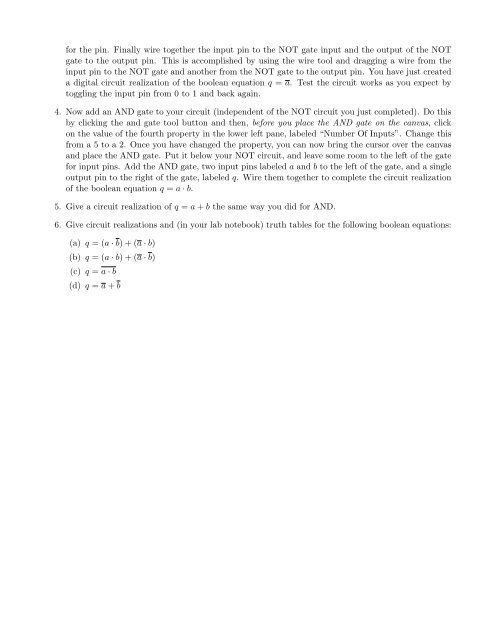
for the pin. Finally wire together the input pin to the NOT gate input and the output of the NOT<br />
gate to the output pin. This is accomplished by using the wire tool and dragging a wire from the<br />
input pin to the NOT gate and another from the NOT gate to the output pin. You have just created<br />
a digital circuit realization of the boolean equation q = a. Test the circuit works as you expect by<br />
toggling the input pin from 0 to 1 and back again.<br />
4. Now add an AND gate to your circuit (independent of the NOT circuit you just completed). Do this<br />
by clicking the and gate tool button and then, before you place the AND gate on the canvas, click<br />
on the value of the fourth property in the lower left pane, labeled “Number Of Inputs”. Change this<br />
from a 5 to a 2. Once you have changed the property, you can now bring the cursor over the canvas<br />
and place the AND gate. Put it below your NOT circuit, and leave some room to the left of the gate<br />
for input pins. Add the AND gate, two input pins labeled a and b to the left of the gate, and a single<br />
output pin to the right of the gate, labeled q. Wire them together to complete the circuit realization<br />
of the boolean equation q = a · b.<br />
5. Give a circuit realization of q = a + b the same way you did for AND.<br />
6. Give circuit realizations and (in your lab notebook) truth tables for the following boolean equations:<br />
(a) q = (a · b) + (a · b)<br />
(b) q = (a · b) + (a · b)<br />
(c) q = a · b<br />
(d) q = a + b


