QUICK REFERENCE - Waterman Industries
QUICK REFERENCE - Waterman Industries
QUICK REFERENCE - Waterman Industries
- No tags were found...

Create successful ePaper yourself
Turn your PDF publications into a flip-book with our unique Google optimized e-Paper software.
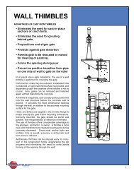
the seal. When unseating heads are to be acting on a flushbottom gate, top wedges shall be added, but bottom wedgeswill not be required. Sealing pressure shall be varied by adjusting side and top wedges.Wall Thimbles and Anchor BoltsWall thimbles shall be provided with all gates except those to be mounted on pipe flanges or those gates to be attached toconcrete headwalls with anchor bolts, as shown on the plans. Each thimble shall be of one-piece cast iron constructionand of the section and depth as specified in the plans and gate schedule. There shall be integrally cast water stop aroundthe periphery of the thimble. The front flange of the thimble shall be machined, drilled and tapped to receive the sluice gateattaching studs. Bolt pattern shall match gate bolt pattern. After machining, the front flange shall be marked with verticalcenterline and the word "top" for correct alignment. Large square and rectangular opening thimbles shall be provided withgrout holes in the invert to permit entrapped air to escape. The holes shall be 1Z\x" in diameter, no more than two feet apartand shall be upstream and downstream of the water stop.A mastic type gasket shall be provided between the sluice gate and the wall thimble. Anchor bolts shall be corrosion resistant.Gates mounted directly upon the headwall shall be sealed between the gate back and wall with a non-shrink grout. Seemanufacturers detailed installation instruction.Stems and Stem CouplingsOperating stems shall be of a size to safely withstand, without buckling or permanent distortion, stresses induced by normaloperating forces. Stems shall be fabricated from round bar stock of cold-finished steel, stainless steel or bronze, as shownon the plans or gate schedule and shall be provided with 29o modified or full acme threads. Stems composed of two or moresections shall be joined by bronze couplings threaded and keyed to stems, or couplings of the same material as the stems,pinned, bolted or welded and pinned to the stems. In section, couplings shall be stronger than the stems. Rising stemswith manual lifts shall be provided with adjustable limit nuts or stop collars above and below the floor stand lift nut to preventover travel of the gate in either direction.Stem GuidesStem guides shall be cast, with bronze bushings, and mounted on cast brackets. Guides shall be adjustable in two directionsand shall be so constructed that when properly spaced they will hold the stem in alignment and still allow enough play topermit easy operation. Stem guide spacing shall be as recommended by the manufacturer, but in no case shall it exceedan l/r ratio of 200. Brackets shall be attached to the wall by anchor bolts and sufficient strength to prevent twisting or saggingunder load.Manually Operated LiftsSluice gates shall be operated manually by handwheel or crank operated pedestal floor stands or bench stands as required.Each lift shall be provided with a threaded cast bronze lift nut to engage the threaded portion of the stem. The lift nut shallhave a machined flange, fitted above and below with thrust ball or roller bearings. Handwheel lifts shall be without gearreduction while crank operated lifts shall have either a single or double reduction. Lifts having a reduction greater than 4:1shall be two-speed. A maximum effort of 40 lbs. pull (25 lb. pull) on handwheel or crank, shall operate the gates under thespecified operating head. The gears, when required, shall be steel with machine-cut teeth. Pinion gears shall be supportedby bronze bushings or roller bearings. The lift mechanism shall be totally enclosed within a cast iron housing adequatelyprovided with lubrication fittings. The pedestal shall be structural steel or cast iron. The crank shall be of cast iron with arevolving brass handle and shall be removable. The crank shall be a maximum of 15" long. All lifts for rising stems shallbe provided with a counter type position indicator and a galvanized steel stem cover or a transparent plastic stem cover withmylar strip position indicator. Non-rising stem gates shall be provided with a counter type position indicator unless extensionstems, valve boxes, or T-handle wrenches make an indicator impractical. Handwheels and crank input shafts shall beapproximately 36" from the operating floor unless otherwise shown. The word "open" shall be cast onto the housing orhandwheel indicating direction of rotation to open the gate.PaintingAll cast iron parts of the sluice gate (not bearing or sliding contact) and stem guides shall be painted in accordance withthe section on painting found elsewhere in these specifications. That portion of the wall thimbles which will be in contactwith concrete shall not be painted.Shop TestingThe completely assembled gate and hoist shall be separately shop-operated to insure proper assembly and operation. Thegate shall be adjusted so that a .004" thick gauge will not be admitted at any point between frame and cover seating surfaces.All gates and equipment shall be inspected and approved by a qualified shop inspector prior to shipment.Storage and InstallationSluice gates and equipment shall be stored and installed in accordance with the installation manual furnished by the gatemanufacturer. After installation the completely assembled gate, stem, guides and lift shall be operated through one full cycleto demonstrate satisfactory operation. Such adjustments as necessary will be made until operation is approved by theengineer. When required by the engineer, the gate shall be subjected to leakage tests and pass the standard requirementsfor maximum leakage as specified in AWWA standards AWWA-C-501.<strong>Industries</strong>10