QUICK REFERENCE - Waterman Industries
QUICK REFERENCE - Waterman Industries
QUICK REFERENCE - Waterman Industries
- No tags were found...

You also want an ePaper? Increase the reach of your titles
YUMPU automatically turns print PDFs into web optimized ePapers that Google loves.
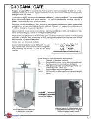
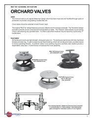
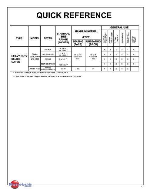
<strong>QUICK</strong> <strong>REFERENCE</strong>GENERAL USETYPE MODEL DETAILSTANDARDSIZERANGE(INCHES)MAXIMUM NORMALSEATING(FACE)(FEET)UNSEATING(BACK)SEWAGETREATMENTWATERTREATMENTFLOODCONTROLIRRIGATIONINDUSTRIALHYDROPOWERHEAVY DUTYSLUICEGATESSeries7000, 5000and 4000Model P-32SQUARERECTANGULAR6 X 6 to144 x 144 **12 X 18 to120 x 180 **55 to 200Varies withSize10 to 75Varies withSizeX X X X X XX X X X X XROUND 6 to 144 ** X X X X X XSELF-CONTAINEDROUNDSELF-CONTAINED120 wide **** INDICATES COMMON SIZES, OTHER LARGER SIZES ALSO AVILABLE.*** INDICATES STANDARD DESIGN, SPECIAL DESIGNS FOR HIGHER HEADS AVAILALBE.X X X X X X6 to 14 60 20 X X X X X<strong>Industries</strong>1
Key to <strong>Waterman</strong> Sluice Gate TerminologyPrefix Series SuffixQ = Flush Bottom Seal 7000 f = Standard FlangebackS = Sluice Gate 5000 ff = Extended FlangebackC = Circular Opening 4000 NRS = Non-Rising StemY = Self-Contained Frame (yoke)X = Special ModificationsI = Inverted (downward opening)Example:S-5000-f-NRS-YSluice Gate with Standard Flange Back, Non-Rising Stem,Self-Contained Gate<strong>Industries</strong>2
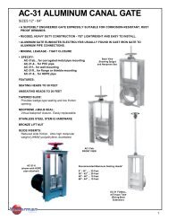
HEAVY DUTY, CAST IRONSERIES 5000AND 7000SLUICE GATESGENERAL DESCRIPTION<strong>Waterman</strong> Series 7000, 5000, 4000 and P-32 Heavy DutySluice Gates are designed and manufactured to meet orexceed AWWA Specifications C-501 (latest revision).USES<strong>Waterman</strong> Heavy Duty Sluice Gates have been successfullyused in a wide variety of applications, including municipalwater works and treatment facilities, flood controlprojects, reservoirs and fish hatcheries.FEATURESGate shapes include square or rectangular with square,rectangular or circular opening, and can be furnished withstandard flangeback or extended flangeback frames.All units feature adjustable corrosion-resistant side wedgesand corrosion-resistant malleable seat facings locked indovetail grooves. All mating or sliding surfaces are fullymachined including close tolerance tongue and grooveguides. All assembly hardware is of corrosion-resistantmaterial.OPTIONAL FEATURESOptional features available include Non-Rising Stem Adaptors,Flush Bottom Closures, Downward Opening Units,Top and Bottom Corrosion Resistant Adjustable Wedges,and fully Self-Contained Gates with extended guide rails,cast iron yoke, stem and lift.SEATING AND UNSEATING HEADSThe basic design of these gates provides adequate safety withgood sealing characteristics for seating and unseating headsas follows:SERIESSeating Heads,Feet (1)Unseating Heads,Feet (2)5000700055 to 200(varies with size)10 to 150or higher(varies with size)(1) Heads are measured from the horizontal center line ofthe gate opening to the surface of the water. With SEATINGHEADS (or face pressure), the water is on the front of thegate and helps to press the seating surfaces together.(2) With UNSEATING HEADS, the water is on the back of thegate and tends to push the slide away from the frame. Topand bottom wedges are usually necessary to overcome thisback pressure. Structures for sluice gates should bedesigned so that the gate is subject to seating pressurewhenever possible. For unseating heads top and bottomwedges are used on all gates having a width of 24" or more,except that gates with flush bottom seats have top wedgesonly.Continued on next page.<strong>Industries</strong>3
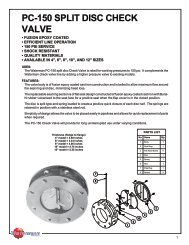
HEAVY DUTY, CAST IRONSERIES 5000AND 7000SLUICE GATESGENERAL DESCRIPTION (continued)FRAMESThe cast iron frames are square or rectangular in shape, ofone piece construction and may have square, rectangular,or circular openings. Standard Flangeback, RectangularExtended Flangeback and Circular Extended Flangebacktypes are available.GUIDE RAILS AND WEDGESCast iron guide rails of a length sufficient to support at leastone-half of the slide when fully opened are cast integrallywith the frame on small and medium size gates and aremounted on fully machined surfaces with dowels andcorrosion resistant fasteners on the larger sizes. Wedgeblock pads are cast as a part of the guide rails and reinforcedwith heavy ribs. The wedge seal faces or adjustablewedge blocks are attached to these. A fully machinedgroove to receive the slide tongue extends the full lengthof each guide. Guides are extra heavy and reinforced fortheir full length to assure maximum rigidity against wedgingpressure and unseating heads when the slide is partiallyopen.SLIDEThe cast iron Slide (Cover) has vertical and horizontalreinforcing ribs, a heavy square nut pocket cast integrallywith the slide, and a machined guide tongue extending thefull length of each side. Minimum tolerances are maintainedbetween the slide tongue and guide grooves toprovide maximum stability of the slide in partially openpositions, thus minimizing chatter. Gates with Non-RisingStems are furnished with a special slide having a heavythrust nut pocket cast integrally with the slide. This pocketis located above the opening of the gate so that at no timewill the stem protrude into the waterway. The thrust nut inthe slide pocket is not secured to the stem and acts as a liftnut as the stem is rotated.SEATSSeating faces are of a corrosion resistant material and aresecured in full width dovetail grooves machined in the castiron frame and slide (see material schedule for alloysavailable). Seat facings are of a work hardening malleabletype and are deformed and locked into place in the grooveswithout the use of fasteners. An accurate and positiveattachment is obtained with the grooves completely filled.The full width dovetail design eliminates the possibility ofleakage between the corrosion resistant seat material andthe castings. The full width dovetail design of the seatingfaces prevents damage to these faces which may occur indovetail designs having overhangs which may work looseduring normal operation of the gate. (See detail drawing)S-7000JOBSITE HANDLING AND INSTALLATIONTo assure proper operation of our gates, care must betaken in the receiving, handling, and storage of all gatesand appurtenances. Installation must be accuratelyperformed. See the <strong>Waterman</strong> Heavy Duty Sluice GateInstallation Manual for complete detailed instructions.<strong>Waterman</strong> Heavy Duty Sluice Gates are completelyassembled in the plant and are given an AWWA C-501inspection by qualified inspectors before shipment.This includes operational, visual and feeler gaugetests. Seat clearance must not pass a .004 gauge.When required, a hydrostatic test can be performedbefore shipment at an extra charge. <strong>Waterman</strong> gates,properly handled, stored and installed should meetthese same standards in operation.Cross SectionSluice Gate Frame and Cover<strong>Industries</strong>4
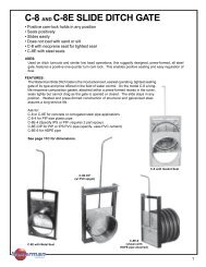
HEAVY DUTY, CAST IRONSERIES 5000AND 7000SLUICE GATESPARTSIDENTIFICATIONNo. Name1 Stem Cover2 Gate Operator (Lift)3 Top Wall Mounting Bracket4 Stem5 Stem Guide6 Stem Coupling7 Top Wedge8 Cover Guide Rail9 Thrust Nut10 Side Wedge11 Frame12 Cover (Slide)13 Thimble14 Bottom Wedge<strong>Industries</strong>5
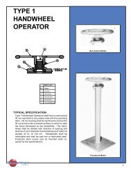
SELF-CONTAINEDSERIES 5000AND 7000SLUICE GATESSelf-contained gates are used when space above thegate installation, or the absence of structural supports,limits the installation of an independent operator.<strong>Waterman</strong> self-contained gates are available in sizesup to 84" x 84" with standard cast yokes, and largersizes with heavy duty fabricated yokes. Heavy dutycast iron yokes are attached to the machined pads onthe gate guides. An extension of the guide providesclearance for the slide to move to the completely openposition. A machined pad on the yoke provides a truesurface for mounting the thrust collar or lift.Self-contained gates may be furnished with risingstems, in which case the stem is secured to a standardslide thrust nut in the normal manner, and operated bya corrosion resistant stem and standard handwheel orcrank type lift. The thrust of opening and closing istransmitted directly through the lift and yoke to thegate. Self-contained gates with non-rising stemsutilize the non-rising stem (NRS) type cover arrangementand a stem having a thrust collar, contained in ahousing on the yoke. Rotating the stem causes thestem block and slide to travel up and down. Theoperating thrust is transmitted directly to the yoke andgate frame.Ball bearing lifts are not recommended for mounting ontop of a self-contained yoke where the lift would besubject to submergence in the liquid being controlled.Special self-contained units with hydraulic cylinderoperators or motorized lifts are available.Non-Rising stems are not recommended for use influids with heavy slurry concentrations as threadedportions of stem may be submerged. Prematurewear may result.<strong>Industries</strong>6
ADJUSTABLEWEDGESYSTEMSThere are two types of <strong>Waterman</strong> wedging systems,"B", and "B-1".<strong>Waterman</strong>StandardType "B" Wedge(Adjustable portionof wedge on slide)Type "B-1" wedges are always provided on <strong>Waterman</strong>computer-controlled machined sluice gates up to 48"in width. Type "B" wedges can be provided for all other<strong>Waterman</strong> heavy duty sluice gates.TYPE "B" WEDGE SYSTEMThe "B" system has been designed to meet thosespecifications wherein the adjustable portion of thewedge must be on the slide. The wedge block facingsurface is securely attached to the reinforced overhangingguide wedge block, double-bolted in shear andpinned to prevent movement. (This design allows foreasy replacement of wedges in the field.)<strong>Waterman</strong>StandardType "B-1" WedgeThe adjustable solid one-piece wedge operates on amachined tongue-and-groove surface, and is locked inplace with a corrosion-resistant stud and adjusting boltwith lock nut.TYPE "B-1" WEDGE SYSTEMThe "B-1" wedging system is designed for unit compatibilitywith all of <strong>Waterman</strong>'s computer-controlled machinedsluice gate surfaces on gates up to 48" in width.The "B-1" wedge, also with computer-controlled machinedsurfaces, assures optimum mating of wedgeand gate surfaces, and a positive, leak-inhibiting closure.Top WedgeTOP AND BOTTOM WEDGESWhen Top and Bottom Wedges are required for unseatingheads, fully adjustable units, made of solid corrosionresistant castings, are provided. These wedgesare easily adjustable and locked into position withcorrosion resistant fasteners. All sliding, mating, andwedging surfaces are fully machined.Bottom Wedge<strong>Industries</strong>7
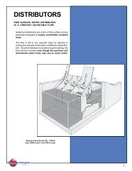
CAST IRON SLUICE GATE WITH"Q-SEAL"FLUSHBOTTOMSEALA "Q-Seal" flushbottom seal gate is used wherever acontinuous smooth opening (without obstructions toimpede solids) is desirable. Typical installations includewastewater settling tanks, aeration tanks, andsedimentation and flocculation basins.CONSTRUCTION FEATURESFlushbottom closures feature a neoprene seal securelycontained at the invert of the frame. The designof this seal provides a flat plane across the bottom ofthe gate without projections into the opening to obstructflow. The seal is mounted on a cast iron bracketand held in place with a corrosion resistant retainer barand fasteners. The seal is firmly supported on threesides, exposing only the flat top side, minimizingdamage from floating objects, wet-dry conditions orsunlight. The seal is easily replaceable without disassemblyof the gate.When a flushbottom seal is used, a smooth roundedprojection on the bottom of the slide replaces thenormal metal seat and seat facing. The slide closesagainst the seal, compressing the neoprene betweenthe slide and frame, making a watertight seal acrossthe bottom of the opening. Bottom wedges are notused as they are not necessary for <strong>Waterman</strong> gateswith a flushbottom closure."Q-Seal "Flushbottom SealRECOMMENDED INSTALLATION CLEARANCESFOR FLUSHBOTTOM GATESGate DiameterorOpening HeightStandardFlangebackGateExtendedFlangebackGateA B A B6" thru 24" 12 7 16 1530" thru 42" 15 7 20 1548" thru 72" 15 9 23 1778" thru 120" 18 10 26 18<strong>Industries</strong>8
TYPICAL SPECIFICATIONSSERIES 7000, 5000, 4000 HEAVY DUTY SLUICE GATESThe following specifications for <strong>Waterman</strong> Heavy Duty Sluice Gates are presented as an aid to the engineer and can beaugmented with additional information to meet specific needs.ScopeThis section covers all heavy duty sluice gates required on the project. Each gate shall be furnished and installed completewith wall thimble or anchor bolts, operating stem, gate lift operator and other appurtenances as specified or needed to makea complete and operable installation.GeneralGates, stems, lifts and other appurtenances shall be the size, type, material and construction as shown on the drawingsand specified herein. Gates shall meet the requirements of AWWA Specifications C-501 (latest revision) or as modified perthese specifications. (They shall be <strong>Waterman</strong> Heavy Duty Sluice Gates or approved equal.) All component parts shall beof the type of material shown, and interchangeable where size and material are the same without grinding, chipping or specialfitting in the field. The gates shall be the product of one manufacturer having five or more years of experience in themanufacture of similar gates for similar use. All mating and sliding parts shall be fully machined. All sluice gate parts,including lift, shall be designed for the heads shown with a minimum safety factor of five.All materials used in the construction of the gates and appurtenances shall be the best suited for the application and shallbe as follows:Frame and Guide RailsThe frame and guide rails shall be cast one-piece construction or may have guides dowelled and bolted to the frame. Framesshall be of the standard flangeback or extended flange type with round or rectangular opening as indicated on the plans andin the sluice gate schedule. A machined dovetail groove for the mounting of the bronze seat facings shall be provided onthe front face of the frame around the full periphery of the opening. The frame shall be provided with cast-on pads whichshall be machined, drilled, and tapped for the mounting of the wedge device. The back of the frame flange shall be machinedto a plane and drilled to match the wall thimble, pipe flange, or anchor bolt pattern. Guide rails shall be of such length asto retain at least one-half of the vertical height of the slide when it is in the fully opened position. A groove running the fulllength of the guide rail shall be accurately machined to receive the slide tongue, with a nominal clearance of 1/16-inch.Cover or SlideThe cover shall be of one piece cast construction with vertical and horizontal ribs, a reinforced pocket to receive the thrustnut, pads to receive the wedges, and a reinforced periphery around the back side of the cover for machining of the dovetailgrooves in which the seating faces shall be mounted. All wedge pads shall be machined, drilled and tapped to receive thewedge devices. The cover shall have fully machined tongues running the full length of each side to properly engage the guiderail grooves. A thrust nut shall be provided to attach the slide to the stem. The nut shall be threaded and, in the case of risingstems, provided with keys on two set screws locked into indents in the stem to prevent rotation of the stem. For non-risingstems, the stem shall turn freely in the thrust nut, to open and close the slides as the stem is rotated.Seating FacesAll seating faces for both covers and frames shall be malleable extruded corrosion resistant material (see materials section)of a shape that will fill and permanently lock in the full width dovetail grooves of the slide and the frame. No other meansof attachment will be allowed. They shall be machined to a 63 micro-inch finish, or better.WedgesAll wedges and wedge blocks shall be solid corrosion resistant material and shall be of sufficient number to provide apractical degree of watertightness. All wedge bearing surfaces and contact faces shall be machined to give maximum contactand wedging action. Wedges shall be fully adjustable, but once set shall not rotate or move from the desired position. Allfasteners and adjustment screws shall be corrosion resistant.Self-Contained Gates with Rising & Non-Rising StemsWhen a self-contained gate is specified, a heavy yoke shall be mounted on the machined pads provided on the upper endsof the guide rails. The yoke shall have a machined bearing surface for the lift nut or pedestal mounting plate. On non-risingstems gates the nut pocket shall be cast on top of the slide so that the stem does not project into the waterway when thegate is fully opened. The thrust generated by gate operation shall be transferred to the yoke by the stem thrust collar or lift.When the operating floor is above the self-contained gate, a stem extension of cold-rolled or stainless steel shall be coupledto the operating stem with a bronze coupling or cast iron stem extension bracket. Operation shall be by a T-handle wrenchor floor stand, shown on the plans and gate schedule. In a T-handle arrangement the stem extension shall be supportedby at least one stem guide or a floor box with integral guide embedded in the operating floor.Flushbottom Sluice GatesWhen a flushbottom closure is specified, a resilient seal shall be attached to the frame so that it is flush with the invert. Itshall be supported by a cast iron bracket which shall be bolted to machined pads provided on the frame. The seal shall beheld in place by a bronze or stainless steel bar which shall be bolted through the seal to the bracket with stainless steelfasteners. The cover (slide) shall be shortened and provided with a smooth rounded surface along the bottom to depress<strong>Industries</strong>9
the seal. When unseating heads are to be acting on a flushbottom gate, top wedges shall be added, but bottom wedgeswill not be required. Sealing pressure shall be varied by adjusting side and top wedges.Wall Thimbles and Anchor BoltsWall thimbles shall be provided with all gates except those to be mounted on pipe flanges or those gates to be attached toconcrete headwalls with anchor bolts, as shown on the plans. Each thimble shall be of one-piece cast iron constructionand of the section and depth as specified in the plans and gate schedule. There shall be integrally cast water stop aroundthe periphery of the thimble. The front flange of the thimble shall be machined, drilled and tapped to receive the sluice gateattaching studs. Bolt pattern shall match gate bolt pattern. After machining, the front flange shall be marked with verticalcenterline and the word "top" for correct alignment. Large square and rectangular opening thimbles shall be provided withgrout holes in the invert to permit entrapped air to escape. The holes shall be 1Z\x" in diameter, no more than two feet apartand shall be upstream and downstream of the water stop.A mastic type gasket shall be provided between the sluice gate and the wall thimble. Anchor bolts shall be corrosion resistant.Gates mounted directly upon the headwall shall be sealed between the gate back and wall with a non-shrink grout. Seemanufacturers detailed installation instruction.Stems and Stem CouplingsOperating stems shall be of a size to safely withstand, without buckling or permanent distortion, stresses induced by normaloperating forces. Stems shall be fabricated from round bar stock of cold-finished steel, stainless steel or bronze, as shownon the plans or gate schedule and shall be provided with 29o modified or full acme threads. Stems composed of two or moresections shall be joined by bronze couplings threaded and keyed to stems, or couplings of the same material as the stems,pinned, bolted or welded and pinned to the stems. In section, couplings shall be stronger than the stems. Rising stemswith manual lifts shall be provided with adjustable limit nuts or stop collars above and below the floor stand lift nut to preventover travel of the gate in either direction.Stem GuidesStem guides shall be cast, with bronze bushings, and mounted on cast brackets. Guides shall be adjustable in two directionsand shall be so constructed that when properly spaced they will hold the stem in alignment and still allow enough play topermit easy operation. Stem guide spacing shall be as recommended by the manufacturer, but in no case shall it exceedan l/r ratio of 200. Brackets shall be attached to the wall by anchor bolts and sufficient strength to prevent twisting or saggingunder load.Manually Operated LiftsSluice gates shall be operated manually by handwheel or crank operated pedestal floor stands or bench stands as required.Each lift shall be provided with a threaded cast bronze lift nut to engage the threaded portion of the stem. The lift nut shallhave a machined flange, fitted above and below with thrust ball or roller bearings. Handwheel lifts shall be without gearreduction while crank operated lifts shall have either a single or double reduction. Lifts having a reduction greater than 4:1shall be two-speed. A maximum effort of 40 lbs. pull (25 lb. pull) on handwheel or crank, shall operate the gates under thespecified operating head. The gears, when required, shall be steel with machine-cut teeth. Pinion gears shall be supportedby bronze bushings or roller bearings. The lift mechanism shall be totally enclosed within a cast iron housing adequatelyprovided with lubrication fittings. The pedestal shall be structural steel or cast iron. The crank shall be of cast iron with arevolving brass handle and shall be removable. The crank shall be a maximum of 15" long. All lifts for rising stems shallbe provided with a counter type position indicator and a galvanized steel stem cover or a transparent plastic stem cover withmylar strip position indicator. Non-rising stem gates shall be provided with a counter type position indicator unless extensionstems, valve boxes, or T-handle wrenches make an indicator impractical. Handwheels and crank input shafts shall beapproximately 36" from the operating floor unless otherwise shown. The word "open" shall be cast onto the housing orhandwheel indicating direction of rotation to open the gate.PaintingAll cast iron parts of the sluice gate (not bearing or sliding contact) and stem guides shall be painted in accordance withthe section on painting found elsewhere in these specifications. That portion of the wall thimbles which will be in contactwith concrete shall not be painted.Shop TestingThe completely assembled gate and hoist shall be separately shop-operated to insure proper assembly and operation. Thegate shall be adjusted so that a .004" thick gauge will not be admitted at any point between frame and cover seating surfaces.All gates and equipment shall be inspected and approved by a qualified shop inspector prior to shipment.Storage and InstallationSluice gates and equipment shall be stored and installed in accordance with the installation manual furnished by the gatemanufacturer. After installation the completely assembled gate, stem, guides and lift shall be operated through one full cycleto demonstrate satisfactory operation. Such adjustments as necessary will be made until operation is approved by theengineer. When required by the engineer, the gate shall be subjected to leakage tests and pass the standard requirementsfor maximum leakage as specified in AWWA standards AWWA-C-501.<strong>Industries</strong>10
MATERIAL SPECIFICATIONS FORHEAVY DUTY SLUICE GATESMaterials used for construction of these gates may bevaried to meet specific operating conditions. Suggestedcombinations are listed below. Many other combinationsand materials are available when required.GATE PARTOR ITEM#1 (STANDARD)BRONZE TRIM#2 STAINLESSTRIM#3 LOW-ZINCBRONZE TRIMMOUNTING MATERIALS#4 NI-RESISTW/MONEL TRIM#5 MONEL & 316 #6 S-5900STAINLESS TRIM RESILIENT SEATEDWall Thimble Cast Iron Cast Iron Cast Iron Ni-Resist Cast Iron Cast IronAnchor Bolts &NutsFrame, Slide andGuide Rails18-8 Stainless (4) 18-8 Stainless (4) 18-8 Stainless (4) Monel 316 Stainless (5) 18-8 StainlessGATE ASSEMBLYCast Iron Cast Iron Cast Iron Ni-Resist Cast Iron Cast IronSeating Faces Naval Bronze 18-8 Stainless (2) Low-Zinc Bronze Monel Monel Rubber/PVC*Wedges Manganese Bronze 18-8 Stainless (3) Low-Zinc Bronze Monel 316 Stainless (6) Manganese BronzeFasteners 18-8 Stainless (4) 18-8 Stainless (4) 18-8 Stainless (4) Monel 316 Stainless (5) 18-8 StainlessStem Block Manganese Bronze Ni-Resist Low-Zinc Bronze Ni-Resist Ni-Resist Manganeze BronzeFLUSHBOTTOM SEALSill Plate Cast Iron Cast Iron Cast Iron Ni-Resist Cast Iron Cast IronSeal Rubber Rubber Rubber Rubber Rubber RubberRetainer 18-8 Stainless (1) 18-8 Stainless (1) 18-8 Stainless (1) Monel 316 Stainless (5) 18-8 Stainless (1)SELF-CONTAINED GATEYoke Cast Iron Cast Iron Cast Iron Ni-Resist Cast Iron Cast IronStem 18-8 Stainless (1) 18-8 Stainless (1) 18-8 Stainless (1) Monel 316 Stainless 18-8 StainlessMATERIAL APPLICATIONS & ASTM STANDARDS:MATERIALUSEASTMSTANDARD NUMBER* Poly Vinyl Chloride (PVC)Cast Iron Major Castings A-126 Class BCast AusteneticGrey Iron(Ni-Resist)Major CastingsA-436-Type 2 or 2BNaval Bronze Seat Faces & Stems B-21 - Alloy 482Low-Zinc Bronze(Silicon Bronze)Low-Zinc Bronze(Silicon Bronze)Seat Faces ASTM B-98Wedges & Stem Blocks B-584 - Alloy 872Manganese Bronze Wedges & Stem Blocks B-584 - Alloy 865Note: For specifications on wall thimbles, lifts and stemguides, see other sections of this catalog.(1)18-8 Stainless Steel(2)18-8 Stainless Steel(3)18-8 Stainless Steel(4)18-8 Stainless Steel(5)316 Stainless Steel(6)316 Stainless SteelMonelRubberStems, Retainers,Anchors & StudsA-582 - Type 303or 276 - Type 304Seat Faces A-276 - Type 304Wedges ASTM A-743Fasteners(Bolts) ASTM F-593(Nuts) ASTM F-594Fasteners, Retainers A-276 - Type 316WedgesSeat Faces,Stems & FastenersFlushbottom Seal,Seat FaceA-296-CF-8MB-164Class A or BNeoprene2000-Grade R-62PVC* Seat Face N/A<strong>Industries</strong>11
HEAVY DUTYMODEL S-5900RESILIENT SEATEDSLUICE GATE• LEAKAGE RATE 100 TIMES BETTERTHAN AWWA C-501 STANDARD• 25 FT. SEATING AND UNSEATINGHEADS• STANDARD WITH FLUSHBOTTOMSEALFEATURES:Resilient seated sluice gates are generally used whereseating or unseating heads do not exceed 25 feet anda very low leakage rate is required.PERFORMANCE:The <strong>Waterman</strong> resilient seated sluice gate has anallowable leakage rate of only .001 gallons per minuteper foot of seating perimeter. This allowable rate is100 times better than the AWWA C-501 Standard of.1 GPM. Our resilient seated sluice gate has beendesigned and tested to withstand both seating andunseating heads of 25 feet of pressure.APPLICATION:With the above exceptions, the <strong>Waterman</strong> Heavy DutySluice Gate with resilient seats is identical to theS-5000 Series Heavy Duty Sluice Gate in virtuallyevery respect. One notable advantage is that thetapered seat is machined at an angle to the guide slotto provide additional wedging action and to minimizewear on the seats by retracting the cover seals from theframe seals upon initial lifting of the cover slide.RESILIENT SEAT DETAIL<strong>Industries</strong>12
TYPICAL SPECIFICATIONSMODEL S-5900 HEAVY DUTY SLUICE GATE WITH RESILIENT SEATSSTORAGE AND INSTALLATIONThe following specifications for <strong>Waterman</strong> Heavy Duty Sluice Gates are presented as an aid to the engineer and can beaugmented with additional information to meet specific needs.SCOPEThis section covers all heavy duty sluice gates required on the project. Each gate shall be furnished and installed completewith wall thimble or anchor bolts, operating stem, gate lift operator and other appurtenances as specified or needed tomake a complete and operable installation.PERFORMANCEThe resilient sluice gates must meet the performance requirements of AWWA C-501 (latest revision) except that theresilient seated sluice gate must allow leakage of no more than .001 gallons per minute per perimeter foot. The resilientseated sluice gate must be able to withstand 25 feet seating, and 25 feet unseating head.GENERALGates, stems, lifts and other appurtenances shall be the size, type, material and construction as shown on the drawingsand specified herein. Gates shall meet the requirements of AWWA Specifications C-501 (latest revision), with theexception of the seats, as modified per these specifications. (They shall be <strong>Waterman</strong> Heavy Duty Sluice Gates or approvedequal). All component parts shall be of the type of material shown, and interchangeable where size and material are thesame without grinding, chipping or special fitting in the field. All mating and sliding metal parts shall be fully machined.All sluice gate parts, including lift, shall be designed for the heads shown with a minimum safety factor of five. All materialsused in the construction of the gates and appurtenances shall be the best suited for the application.FRAME AND GUIDE RAILSThe frame and guide rails shall be cast one-piece construction or may have guides dowelled and bolted to the frame.Frames shall be standard or extended flange type with round or rectangular opening as indicated on the plans and in thesluice gate schedule. Frames shall be of flushbottom design, with a resilient seal attached to the frame so that it is flushwith the invert. The frame shall be provided with cast-on pads which shall be machined, drilled, and tapped for the mountingof the wedge devices. The back of the frame flange shall be machined to a plane and drilled to match the wall thimble,pipe flange, or anchor bolt pattern. Guide rails shall be of such length as to retain at least one-half of the vertical heightof the slide when it is in the fully opened position. A groove running the full length of the guide rail shall be accuratelymachined to receive the slide tongue, with a nominal clearance of 1/16 inch.COVER OR SLIDEThe cover shall be of one piece cast construction with vertical and horizontal ribs, a reinforced pocket to receive the thrustnut, and pads to receive the wedges. All wedge pads shall be machined, drilled and tapped to receive the wedge devices.The cover shall have fully machined tongues running the full length of each side to properly engage the guide rail grooves.A thrust nut shall be provided to attach the slide to the stem. The nut shall be threaded and, in the case of rising stems,provided with keys or two set screws locked into indents in the stem to prevent rotation of the stem. For non-rising stems,the stem shall turn freely in the thrust nut to open and close the slides as the stem is rotated.SEATING FACESSeats shall be of a resilient material, which is both abrasion and corrosion resistant. The seat material on both the frameand the cover (slide) shall be permanently attached.WEDGESAll wedges and wedge blocks shall be solid corrosion resistant material and shall be of sufficient number to provide apractical degree of watertightness. All wedge bearing surfaces and contact faces shall be machined to maximize contactand wedging action. Wedges shall be fully adjustable, but once set shall not rotate or move from the desired position.All fasteners and adjustment screws shall be corrosion resistant.TESTING, SHOPThe gate shall be adjusted so that the seats are slightly compressed and there is no clearance at any point between frameand cover seating surfaces.TESTING, FIELDSame as AWWA C-501-80, Sec. 6.3 except leakage requirements as specified above.OTHER SPECIFICATIONSSee pages 10 and 11 of Heavy Duty Sluice Gate Specifications for such other items as:Wall Thimbles and Anchor BoltsStem GuidesStems and Stem CouplingsPaintingManually Operated LiftsStorage and InstallationSelf-Contained Gates with Rising and Non-Rising Stems<strong>Industries</strong>13
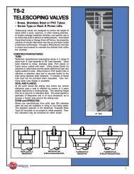
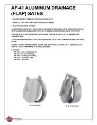
S-5000 & SC-5000,S-5900 & SC-5900 ***SQUARE OR ROUND OPENINGSLUICE GATESPARTSNo. Name1 Frame2 Cover3 Thrust Nut4 Cover Wedge Assembly5 Guide Rails6 Guide Rail Wedge Assembly7 Top Wedge Assembly8 Bottom Wedge Assembly9 Fasteners10 SeatsNOTES:1. SC Series shown. S Series gate has square opening.2. Top of NRS cover or top of wedges.GATESIZE-** A B C D E F J1* G J2*6 9³⁄4 6¹⁄2 14¹⁄2 15 9 4¹⁄2 13 7¹⁄28 10¹⁄8 8 17 19 9 4¹⁄2 13 7¹⁄210 12 9¹⁄2 19 22 9 5 13 8¹⁄212 14¹⁄4 10 ³⁄8 20 ³⁄4 25 9 ¹⁄2 5 13¹⁄2 8¹⁄214 16 11¹⁄2 23 28 9 ¹⁄2 5 13¹⁄2 8¹⁄215 17 11¹⁄2 23 29¹⁄2 9 ¹⁄2 5 13¹⁄2 8¹⁄216 18 12 ¹⁄2 25 31 9 ¹⁄2 5 13¹⁄2 8¹⁄218 20³⁄4 13 ¹⁄2 27 34 11 ¹⁄2 6¹⁄4 15¹⁄2 105⁄820 23³⁄4 15 30 37 11 ¹⁄2 6³⁄8 15¹⁄2 10¹⁄221 24 15 30 37¹⁄2 11 ¹⁄2 6³⁄8 15¹⁄2 97⁄824 28¹⁄2 16 ³⁄4 33 43 11 ¹⁄2 7¹⁄2 15¹⁄2 11 ¹⁄230 37¹⁄2 19 ³⁄4 39 52 12¹⁄2 7 17 11 ¹⁄236 41¹⁄2 22¹⁄2 45 61 12¹⁄2 7 17 11 ¹⁄242 47¹⁄2 26¹⁄2 52 ¹⁄2 70 12¹⁄2 8 17 1248 51¹⁄4 29 57 79 14 8 19 12* Add for grout pad thickness if applicable.** Square or RoundGATESIZE**A B C D E F J1* G J2*54 59¹⁄4 33 66 88 15¹⁄2 8¹⁄2 20 12¹⁄260 64 36 72 97 15¹⁄2 8³⁄4 20 12¹⁄266 68 39 78 107 15¹⁄2 9 20 12¹⁄272 74 42 84 116 15¹⁄2 9 20 13¹⁄478 84 45 90 125 15¹⁄2 10 20 13³⁄484 87 47¹⁄2 95³⁄4 133 18¹⁄2 9¹⁄2 23 13³⁄490 94 53 106 142 18¹⁄2 11 23 15¹⁄496 100 56 112 151 18¹⁄2 11 23 15¹⁄4108 110 62 124 170 20 11 25 15¹⁄2120 124 68 136 188 20 11 25 15¹⁄2132 134 74 148 206 20 12¹⁄2 25 16³⁄4* Add for grout pad thickness if applicable.** Square or Round*** Size limitations may apply to models S-5900 and SC-5900NOTE: FOR PRELIMINARY DESIGN PURPOSES ONLYDO NOT USE FOR INSTALLATIONUNLESS PART OF CERTIFIED & APPROVED SUBMITTAL<strong>Industries</strong>14
S-5000 & S-5900 RECTANGULAR OPENING (See drawing page 15)GATESIZEB C D E F J1 G J212 X 18 20³⁄4 13¹⁄2 20³⁄4 34 11¹⁄2 5 15¹⁄2 8³⁄412 X 24 28¹⁄2 17¹⁄4 21 43 11¹⁄2 7 15¹⁄2 1112 X 36 38 22¹⁄2 20³⁄4 61 12¹⁄2 7 17 1115 X 18 20³⁄4 13¹⁄2 24 34 11¹⁄2 6¹⁄4 15¹⁄2 97⁄818 X 6 9³⁄4 7¹⁄2 27 15 11¹⁄2 6¹⁄4 15¹⁄2 918 X 12 16³⁄4 9³⁄4 26 25 9¹⁄4 4³⁄4 15¹⁄2 8¹⁄218 X 24 26¹⁄2 16³⁄4 27¹⁄4 43 11¹⁄2 7 15¹⁄2 1118 X 30 37¹⁄2 19³⁄4 27 52 12¹⁄2 7 17 1118 X 36 38 22¹⁄2 27 61 12¹⁄2 7 17 1118 X 48 51¹⁄4 29 27 79 14 7 19 11¹⁄218 X 72 74³⁄8 41 27 116 14 7 19 11¹⁄224 X 12 14¹⁄4 10³⁄4 33 25 11¹⁄2 6¹⁄2 15¹⁄2 9¹⁄224 X 18 19 13¹⁄2 33 34 11¹⁄2 7 15¹⁄2 10³⁄424 X 30 37¹⁄2 19³⁄4 33 52 12¹⁄2 7 17 1124 X 36 38 22¹⁄2 33 61 12¹⁄2 7 17 11¹⁄224 X 42 47¹⁄4 26¹⁄2 33 70 12¹⁄2 7 17 11¹⁄224 X 48 50 29 33¹⁄2 79 14 7 19 1130 X 18 20³⁄4 13¹⁄2 39 34 12¹⁄2 7 17 11¹⁄230 X 24 28¹⁄2 16¹⁄2 39 43 12¹⁄2 7 17 11¹⁄230 X 36 41¹⁄4 22¹⁄2 39 61 12¹⁄2 7 17 1130 X 42 47¹⁄2 26¹⁄2 40¹⁄2 70 12¹⁄2 8 17 1230 X 48 51¹⁄4 29¹⁄2 41 79 14 8 19 1230 X 60 64 36 42 97 15¹⁄2 8 20 12¹⁄230 X 72 75 42 42 116 15¹⁄2 8 20 12¹⁄236 X 12 14¹⁄4 10³⁄4 45¹⁄2 25 12¹⁄2 7 17 1136 X 18 20³⁄4 13³⁄4 45¹⁄2 34 12¹⁄2 7 17 1136 X 24 28¹⁄2 16³⁄4 45 43 12¹⁄2 7 17 1136 X 30 32 19³⁄4 45 52 12¹⁄2 7 17 1136 X 42 47¹⁄4 26 46 70 12¹⁄2 8 17 1236 X 48 51¹⁄4 29¹⁄2 47 79 14 8 19 1236 X 60 64 36 48 97 15¹⁄2 8 20 12¹⁄236 X 72 74 42 48 116 15¹⁄2 8 20 12¹⁄236 X 84 87 48 48 139 18¹⁄2 9¹⁄2 23 13³⁄439 X 84 87 48 51 139 18¹⁄2 9¹⁄2 23 13³⁄442 X 30 37¹⁄2 20¹⁄4 52¹⁄2 52 12¹⁄2 8 17 1242 X 36 41¹⁄2 23¹⁄4 52¹⁄2 61 12¹⁄2 8 17 1242 X 48 51¹⁄4 29 52¹⁄2 79 14 8 19 1242 X 54 66¹⁄4 32¹⁄4 52¹⁄2 91 12¹⁄2 8 17 1242 X 60 64 36 54 97 15¹⁄2 8 20 12¹⁄242 X 72 74¹⁄4 42 54¹⁄4 116 15 8 20 12¹⁄248 X 24 28¹⁄2 17 58 43 14 8 19 1248 X 30 32 20¹⁄2 59 52 14 8 19 1248 X 36 38 23¹⁄2 59 61 14 8 19 1248 X 42 47¹⁄2 26¹⁄2 59 70 14 8 19 1248 X 54 59¹⁄4 33 60 88 14 8 19 12¹⁄248 X 60 62¹⁄2 36 60 97 15¹⁄2 8 20 12GATESIZE B C D E F J1 G J248 X 72 74 42 60 116 15¹⁄2 9 20 13¹⁄448 X 84 87 48 60 133 18¹⁄2 9 23 1348 X 96 100 56 64 155 18¹⁄2 11 23 15¹⁄448 X 120 124 68 64 187 20 11 25 15¹⁄254 X 24 28¹⁄2 18 66 43 15¹⁄2 8¹⁄2 20 12¹⁄254 X 36 41¹⁄2 24 66 61 15¹⁄2 8 20 1254 X 48 51¹⁄4 30 66 79 15¹⁄2 8¹⁄2 20 12¹⁄254 X 60 64 36 66 97 15¹⁄2 8³⁄4 20 12¹⁄254 X 72 75 42 66 116 15¹⁄2 9 20 13¹⁄454 X 84 87 48 66 133 14 8¹⁄2 21¹⁄4 1260 X 36 38 24 72 61 15¹⁄2 8 20 1260 X 48 52¹⁄2 30 72 79 15¹⁄2 8¹⁄2 20 12¹⁄260 X 72 74 42 72 116 15¹⁄2 9 20 13¹⁄460 X 84 87 48 72 133 18¹⁄2 8¹⁄2 23 1260 X 96 100 56 76 151 18¹⁄2 11 23 1560 X 120 124 68 76 191 20 13 25 15¹⁄272 X 36 41¹⁄2 24 84 61 15¹⁄2 8 20 1272 X 48 51¹⁄2 30 84 79 15¹⁄2 9 20 1372 X 54 56 33 84 88 15¹⁄2 9 20 12¹⁄272 X 60 63¹⁄4 36 84 97 15¹⁄2 9 20 13¹⁄472 X 84 87 477⁄8 84 133 18¹⁄2 9³⁄4 23 13³⁄472 X 96 100 56 88 151 18¹⁄2 11 23 15¹⁄472 x 108 110 62 88 170 14 11 19 15¹⁄284 x 48 52 30 96 79 18¹⁄2 8 23 12¹⁄284 x 60 64 36 96 97 18¹⁄2 8¹⁄2 23 1284 x 66 68 39 96 107 18¹⁄2 9¹⁄2 23 13³⁄484 x 72 74³⁄8 42 96 115 18¹⁄2 9¹⁄2 23 13³⁄484 x 108 110 62 100 170 14 11 19 15¹⁄296 x 24 28¹⁄2 18 108 43 18¹⁄2 10¹⁄2 23 14¹⁄296 x 36 41¹⁄2 24 108 61 18¹⁄2 10¹⁄2 23 14¹⁄296 x 42 47¹⁄2 27 108 70 14 10¹⁄2 19 14¹⁄296 x 60 64 36 108 97 18¹⁄2 11 23 15¹⁄496 x 72 74 44 112 116 18¹⁄2 11 23 15¹⁄496 x 120 124 68 112 187 20 11 25 15¹⁄4102 x 78 82 45 114 124 20 11 25 16108 x 60 64 38 124 97 20 11 25 15108 x 72 74 44 124 116 20 11 25 15108 x 84 87 50 124 133 20 11 25 15¹⁄2108 x 120 124 68 124 187 20 12 25 16¹⁄2108 x 144 150 80 124 225 20³⁄4 12¹⁄2 27¹⁄4 17³⁄4120 x 60 64 36 136 97 18¹⁄2 11 23 15¹⁄4120 x 72 74 44 136 116 20 11 25 15¹⁄2120 x 84 87 50 136 133 20 11 25 15¹⁄2120 x 96 100 56 136 151 20 11 25 15¹⁄2120 x 108 110 62 136 175 20 11 25 15¹⁄2120 x 132 134 74 136 208 21³⁄4 12¹⁄2 27¹⁄4 18144 x 84 87 50 160 133 22 11 27 15<strong>Industries</strong>15
S-5000-Y, SC-5000-Y, S-5900-Y & SC-5900-Y **SELF-CONTAINED SLUICE GATE1. SC Series shown. S Series gate has squareopening.2. Type 1 lift shown. Geared lifts also available.3. All gates are available with special heightfabricated steel or stainless steel yokes.PARTSNo. Name1 Frame2 Cover3 Thrust Nut4 Side Wedge Assy.5 Guide Rail6 NRS Bracket7 Yoke8 Lift Collar9 Lift Nut10 Seats (non-corrosive)GATESIZEA B C D F J1* G J2*6 16 6¹⁄2 14¹⁄2 9¹⁄2 4¹⁄2 13¹⁄2 7¹⁄28 21¹⁄2 8 17 9¹⁄2 4¹⁄2 13¹⁄2 7¹⁄210 24¹⁄2 9¹⁄2 19 9¹⁄2 5 13¹⁄2 8¹⁄212 27³⁄8 10³⁄8 20³⁄4 10 5 14 8¹⁄214 30 11¹⁄2 23 10 5 14 8¹⁄215 31³⁄4 11¹⁄2 23 10 5 14 8¹⁄216 33¹⁄2 12¹⁄2 25 10 5 14 8¹⁄218 37 13¹⁄2 27 12 6¹⁄4 16 105⁄820 41¹⁄2 15 30 12 6³⁄8 16 10¹⁄221 41¹⁄2 15 30 12 6³⁄8 16 1024 46 16³⁄4 33 12 7¹⁄2 16 11¹⁄230 55 19³⁄4 39 13 7 17¹⁄2 11¹⁄236 64 22¹⁄2 45 13 7 17¹⁄2 11¹⁄242 73¹⁄2 26¹⁄2 52¹⁄2 13 8 17¹⁄2 1248 82 29 57 14¹⁄2 8 19¹⁄2 1254 111 33 66 15¹⁄2 8¹⁄2 20 12¹⁄260 116 36 72 15¹⁄2 8³⁄4 20 12¹⁄266 127 39 78 15¹⁄2 9 20 12¹⁄272 138 42 84 16³⁄4 9¹⁄4 20³⁄4 13¹⁄478 141 45 90 15¹⁄2 10 20 13³⁄484 150 47¹⁄2 95³⁄4 18¹⁄2 9¹⁄2 23 13³⁄4* Add for grout pad thickness if applicable.** Size limitations may apply to models S-5900 and SC-5900.GATESIZE B C D F J1 G J212 x 24 44 17¹⁄4 21 11¹⁄2 7 15¹⁄2 1112 x 36 62³⁄8 22¹⁄2 20³⁄4 12¹⁄2 7 17 1115 x 18 36¹⁄2 13¹⁄2 24 11¹⁄2 6¹⁄4 15¹⁄2 97⁄818 x 6 26 7¹⁄2 27 11¹⁄2 6¹⁄4 15¹⁄2 918 x 30 55 19³⁄4 27 12¹⁄2 7 17 1118 x 36 635⁄8 22¹⁄2 27 12¹⁄2 7 17 1124 x 18 37¹⁄4 13¹⁄2 33 11¹⁄2 7 15¹⁄2 10³⁄424 x 30 55 19³⁄4 33 12¹⁄2 7 17 1124 x 36 63¹⁄2 22¹⁄2 33 12¹⁄2 7 17 11¹⁄224 x 48 81 29 33¹⁄2 14 7 19 1130 x 18 38¹⁄4 13¹⁄2 39 12¹⁄2 7 17 11¹⁄230 x 24 46 16¹⁄2 39 12¹⁄2 7 17 11¹⁄230 x 36 64³⁄4 22¹⁄2 39 12¹⁄2 7 17 1130 x 42 73¹⁄2 26¹⁄2 40¹⁄2 12¹⁄2 8 17 1230 x 60 104 36 42 15¹⁄2 8 20 12¹⁄242 x 36 67¹⁄2 23¹⁄4 52¹⁄2 12¹⁄2 8 17 1242 x 54 95 32¹⁄4 52¹⁄2 12¹⁄2 8 17 1248 x 24 59¹⁄4 17 58 14 8 19 1248 x 30 62³⁄4 20¹⁄2 59 14 8 19 1248 x 42 73¹⁄2 26¹⁄2 59 14 8 19 1248 x 60 102³⁄4 36 60 15¹⁄2 8 20 12<strong>Industries</strong>16
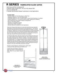
CAST IRONSERIES 4000SLUICE GATEHEAVY DUTY • AWWA C501 & BRITISH STANDARDMETRIC & U.S. DIMENSIONSAPPLICATIONS:• WATER TREATMENT PLANTS• WASTEWATER TREATMENT PLANTS• FLOOD CONTROL• DISTRIBUTION SYSTEMS• WATER CONTROLFEATURES:Available in Metric or U.S. Standard dimensions, theSeries 4000 Sluice Gates are manufactured for heavyduty use. Computer designed for maximum strength toweight ratios, the Series 4000 features CNC machining,permanent dovetail seating surfaces, and fullyadjustable cover mounted side wedges with machinedcontact surfaces. Top and bottom wedges are availableto meet specific unseating requirements. Althoughthimble mounting is preferred, the gate can bemanufactured for direct wall mounting or for spigot typeinstallation.VARIATIONS:ASTM STD.Manganese BronzeB584 Alloy 865Alloy 872316 Stainless SteelA296 CF 8M304 Stainless A296CF 8WEDGESBRITISH STD.BS 1400 HTB 1BS 1400 PB 4CBS 3100/1632-Gr. BBS 3100/1631-Gr. AASTM STD.Cast iron A-126 ClassB 30,000# TensileNi-Resist A-436Type 2 or 2BFRAME andCOVER CASTINGSBRITISH STD.BS 14 S2 Grade 220BS 3468 L-NiCr20 3DOVETAIL SEATSASTM STD.BRITISH STD.Naval Bronze B21 Alloy 482 BS 2874 CZ114Silicon Bronze ASTM B-98 BS 2874 PB102Stainless Steel A276 Type 304 BS 970 Pt 4 304 S 15COATINGSCoal Tar EpoxyFusion EpoxyAsphalt VarnishEnamelSTEMSASTM STD.BRITISH STD.Stainless Steel A276 Type 304 BS 970 Pt 4 316 S 15Stainless Steel A276 Type 316 BS 970 Pt 4 316 S 16Naval Bronze B21 Alloy 482 BS 2874 CZ 114ADDITIONAL OPTIONSTop & Bottom WedgingFlushbottomSelf-ContainedExtended FlangebackOther materials & finishesavailable to meet specifications<strong>Industries</strong>19
S-4000 METRICSTANDARDFLANGEBACKEXTENDEDFLANGEBACKFOR GATES WITHFLUSHBOTTOMNo.NamePARTS1 Frame (shown as self-contained)2 Cover3 Thrust Nut4 Side Wedge Ass'y.5Guide Rail, Cast on (integral with frame)14" and larger6 Thrust Nut Pocket7 Yoke, Cast on (integral with frame)8 Lift Collar9 Lift Nut10 Seats (non-corrosive)GATESIZES-4000 GATE DIMENSIONS IN MILLIMETERSA 2 B C D F 1 G 1 H1* H2* K* L M N O P Q150 152 346 152 282 121 191 64 102 127 24 190 102 254 254 356200 203 422 178 333 121 191 64 102 127 24 241 102 254 254 356250 254 498 203 384 121 191 64 102 127 24 292 102 254 254 356300 305 583 235 445 149 216 89 133 155 24 343 102 279 254 381350 356 767 305 610 210 295 127 197 213 27 432 127 356 305 457380 381 767 305 610 210 295 127 197 213 27 432 127 356 305 457400 406 805 318 635 210 295 127 197 213 27 462 127 356 305 457450 457 884 343 686 210 305 127 197 222 27 508 127 356 305 457500 508 967 369 738 210 295 127 197 213 27 558 127 356 305 457600 610 1224 419 838 210 298 127 197 224 27 660 127 356 305 457700 700 1360 465 930 226 311 127 197 213 27 750 127 356 305 457750 762 1452 495 991 226 324 133 197 229 30 838 127 356 305 457800 800 1530 515 1030 226 324 133 197 229 30 860 127 356 305 457900 914 1681 571 1143 226 324 133 197 229 30 991 127 356 305 4571. Minimum required clearance dimensions.2. Actual.1000 1000 1810 615 1230 222 324 133 197 229 30 1050 127 356 305 4571050 1066 1975 648 1295 248 362 165 241 279 38 1118 127 381 356 5081200 1219 2199 724 1448 273 381 165 241 279 38 1273 127 381 356 508* Add for grout pad if applicable<strong>Industries</strong>NOTE: FOR PRELIMINARY DESIGN PURPOSES ONLYDO NOT USE FOR INSTALLATIONUNLESS PART OF CERTIFIED & APPROVED SUBMITTAL20
S-4000 INCHESNo. NamePARTS1 Frame (shown as self-contained)2 Cover3 Thrust Nut4 Side Wedge Ass'y.Guide Rail, Cast on (integral with frame)514" and larger6 Thrust Nut Pocket7 Yoke, Cast on (integral with frame)8 Lift Collar9 Lift Nut10 Seats (non-corrosive)FOR GATES WITHFLUSHBOTTOM1. S Series shown. SC Series has circular opening.2. Minimum required clearance dimensions.STANDARDFLANGEBACKEXTENDEDFLANGEBACKGATES IZES -4000 GATE D IM E N S IONS IN INCHESA B C D F 2 G 2 H1* H2* K * L M N O P Q6 13 5⁄8 6 11¹⁄8 4³⁄4 7¹⁄2 2¹⁄2 4 5 ¹5⁄16 7¹⁄2 4 10 10 148 18 5⁄8 7 13¹⁄8 4³⁄4 7¹⁄2 2¹⁄2 4 5 ¹5⁄16 9¹⁄2 4 10 10 1410 19 5⁄8 8 15¹⁄8 4³⁄4 7¹⁄2 2¹⁄2 4 5 ¹5⁄16 11¹⁄2 4 10 10 1412 22¹5⁄16 9¹⁄4 17¹⁄2 57⁄8 8¹⁄2 3¹⁄2 5¹⁄4 6¹⁄8 ¹5⁄16 13¹⁄2 4 14 10 1514 30 ³⁄16 12 24 8¹⁄4 115⁄8 5 7³⁄4 8³⁄8 1¹⁄16 17 5 14 12 1815 30 ³⁄16 12 24 8¹⁄4 115⁄8 5 7³⁄4 8³⁄8 1¹⁄16 17 5 14 12 1816 31¹¹⁄16 12¹⁄2 25 8¹⁄4 115⁄8 5 7³⁄4 8³⁄8 1¹⁄16 18³⁄16 5 14 12 1818 34¹¹⁄16 13¹⁄2 27 8¹⁄4 12 5 7³⁄4 8³⁄4 1¹⁄16 20 5 14 12 1820 38 ¹⁄16 14¹⁄2 29 8¹⁄4 115⁄8 5 7³⁄4 8³⁄8 1¹⁄16 22 5 14 12 1824 48³⁄16 16¹⁄2 33 8¹⁄4 11³⁄4 5 7³⁄4 8¹¹⁄16 1¹⁄16 26 5 14 12 1827¹⁄2 539⁄16 18¹5⁄16 365⁄8 87⁄8 12¹⁄4 5 7³⁄4 8³⁄8 1¹⁄16 29¹⁄2 5 14 12 1830 57³⁄16 19¹⁄2 39 87⁄8 12³⁄4 5¹⁄4 7³⁄4 9 1³⁄16 33 5 14 12 1831¹⁄2 60¹⁄4 20¹⁄4 409⁄16 87⁄8 12³⁄4 5¹⁄4 7³⁄4 9 1³⁄16 337⁄8 5 14 12 1836 66³⁄16 22¹⁄2 45 87⁄8 12³⁄4 5¹⁄4 7³⁄4 9 1¹⁄4 39 5 14 12 1839³⁄8 71¹⁄4 24¹⁄4 487⁄16 8³⁄4 12³⁄4 5¹⁄4 7³⁄4 9 1¹⁄4 415⁄16 5 14 12 1842 77³⁄4 25¹⁄2 51 9³⁄4 14¹⁄4 6¹⁄2 9¹⁄2 11 1¹⁄2 44 5 15 14 2048 869⁄16 28¹⁄2 57 10³⁄4 15 6¹⁄2 9¹⁄2 11 1¹⁄2 50¹⁄8 5 15 14 20*Add for grout pad if applicable<strong>Industries</strong>NOTE: FOR PRELIMINARY DESIGN PURPOSES ONLYDO NOT USE FOR INSTALLATIONUNLESS PART OF CERTIFIED & APPROVED SUBMITTAL21