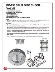
ss-250 series stainless steel slide gate - Waterman Industries
ss-250 series stainless steel slide gate - Waterman Industries
ss-250 series stainless steel slide gate - Waterman Industries
- No tags were found...

Create successful ePaper yourself
Turn your PDF publications into a flip-book with our unique Google optimized e-Paper software.
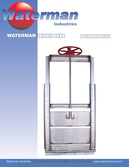
<strong>Industries</strong>WATERMAN 1<strong>Waterman</strong> <strong>Industries</strong> • P.O. Box 458 Exeter, CA 93221 • (800)331-0808 • www.watermanusa.com
Leaders in Water Management Since 1912Table of ContentsOverview ……………………………………………………………………………………………………………………………. 3Selection Chart ……………………………………………………………………………………………………………………. 4Typical Drawings:SS-251-0 ………………………………………………………………………………………………………………………………. 5SS-252-0 ………………………………………………………………………………………………………………………………. 6SS-253-0 ………………………………………………………………………………………………………………………………. 7SS-254-0 ………………………………………………………………………………………………………………………………. 8QSS-256-0 ……………………………………………………………………………………………………………………………. 9SS-257-0 ……………………………………………………………………………………………………………………………… 10SS-251-1 ……………………………………………………………………………………………………………………………… 11SS-252-1 ……………………………………………………………………………………………………………………………… 12SS-253-1 ……………………………………………………………………………………………………………………………… 13SS-254-1 ……………………………………………………………………………………………………………………………… 14QSS-256-1 …………………………………………………………………………………………………………………………… 15SS-257-1 ……………………………………………………………………………………………………………………………… 16Actuator Options – Self Contained Gates ……………………………………………………………………………. 17Actuator Options – Non-Self Contained Gates ……………………………………………………………………. 18Non-Rising Stem, Non-Self Contained Gates ………………………………………………………………………. 19Gate Mounting Configurations ………………………………………………………………………………………..…. 20Typical Specifications ………………………………………………………………………………………………..…. 21 - 24• GNI <strong>Waterman</strong> LLC • P.O. Box 458 • 25500 Road 204 • Exeter, California 93221 • Phone (559) 562-4000 • FAX (559) 562-2277 •2
SS-<strong>250</strong> SERIESSTAINLESS STEELSLIDE GATE• THE BEST OF TECHNOLOGY FOR STRENGTH ANDLONGEVITY IN CORROSIVE ATMOSPHERES• 304 OR 316 STAINLESS STEEL WITH UHMWPLASTIC SLIDING AND SEATING SURFACES• LEAKAGE IS GUARANTEED TO NO MORE THAN 0.05GPM/FT OF SEAL PERIMETER, WHICH IS ½ THATALLOWED BY AWWA STANDARDSADVANTAGES AND PERFORMANCE Corrosion Resistant Optimum Sealing Against Leakage Rugged Heavy Duty Design Low MaintenanceSS-<strong>250</strong> Series Slide Gates are engineered for excellent sealing whileproviding maximum resistance to corrosion. Ultra High MolecularWeight Polyethylene (UHMW) sliding and seating surfaces, di<strong>ss</strong>imilarfrom the <strong>gate</strong> <strong>slide</strong> material, provides low coefficient of friction whilemaintaining the superior resistance to corrosion. SS-<strong>250</strong> Series <strong>gate</strong>smay be specified with optional type 316L stainle<strong>ss</strong> <strong>steel</strong> for use inunusually corrosive environments such as hydrogen sulfides or saltwater.SS-251-1(shown)SS-<strong>250</strong> Series Slide Gates are designed to maintain leakage at½ that allowed by AWWA. SS-<strong>250</strong> <strong>gate</strong>s are available innormal aperture configurations, channel (embedded or bolted)as well as weirs (downward opening). They may also beordered as self-contained <strong>gate</strong>s or with extension stems andseparate operators. SS-<strong>250</strong> Gates are custom designed tomeet seating and unseating heads per application,incorporating safety factors per AWWA standards.SS-<strong>250</strong> Gates can also be designed to incorporate integral withthe frame. SS-<strong>250</strong> Gate frames may be embedded in channelwalls, mounted to a wall with anchor bolts, mounted to pipeflange, or wall thimble (<strong>Waterman</strong> offers a complete line of wallthimbles, including “F”, “E”, Spigot-Style, as well as customthimbles).Also available: A-<strong>250</strong> Series Aluminum Slide Gates.TYPE OFGATE(OPENING)RISINGSTEMMACHINEDFLANGECIRCULARFLANGEFULLYCONTAINEDSLIDE INGUIDE RAILSELF-CONTAINEDGATESS-<strong>250</strong> STAINLESS STEEL SLIDE GATE CONFIGURATIONSAPERTURE END OF CHANNEL IN CHANNELSTANDARD DOWNWARDOPENINGDOWNWARDUPWARDOPENINGOPENING(WEIR)NonRestrictedFlowEMBEDDEDGUIDEWALLMTD.GUIDE251 252 253 254 255 256 257251-F 252-F251-CF252-CF251-L 252-L 253-L 254-L 255-L 256-L 257-L251-Y 252-Y 253-Y 254-Y 255-Y 256-Y 257-YNRS Cover 251-N 252-N 253-N 254-N 255-N 256-N 257-NSPECIAL ORMODIFIEDAPPLICATION251-X 252-X 253-X 254-X 255-X 256-X 257-X3
SS-<strong>250</strong> SERIES GATE SELECTION CHART10090807060HEAD(ft)TO INVERT5040SS-<strong>250</strong>-0SS-<strong>250</strong>-1SS-<strong>250</strong>-2SS-<strong>250</strong>-3302010012 24 36 48 60 72 84 96 108 120GATE WIDTH(in)NOTES:1) SS <strong>250</strong>-0 NOT AVAILABLE TALLER THAN 60 INCHES2) FORMULA TO DETERMINE SEAT PRESURE:GATEWIDTH(in)*HEAD(ft)*.21664
8 X 3 BLOCK OUT &GROUT FILL BY OTHERSINVERTALTERNATE "Q" BOTTOMGATE FULL OPEN36" TYP.RECOMMENDED FORHANDWHEEL ORHANDCRANK34-1/2CSECTIONCD4 1/2CINVERTBE34-1/2AINVERTSECTIONBAA + 6A + 9B34-1/21 INCH GROUT PAD-BY OTHERSA = GATE OPENING WIDTHB = GATE OPENING HEIGHTC = GUIDE RAIL HEIGHT = B + 1/2 OF SLIDED = GATE FULL OPEN = 2B + 4-1/2E = SLIDE HEIGHT = B + 4-1/2SECTIONASS-251-0SLIDE GATE5
36" TYP.RECOMMENDED FORHANDWHEEL ORHANDCRANKINVERT34-1/2SECTIONCB34-1/2EBA4-1/2INVERTCCDSECTIONBGATE FULL OPENAA + 634-1/2A + 91 INCH GROUT PAD-BY OTHERSA = GATE OPENING WIDTHB = GATE OPENING HEIGHTC = GUIDE RAIL HEIGHT = B + 1/2 OF SLIDED = GATE FULL OPEN = B + 4-1/2E = SLIDE HEIGHT = B + 4-1/2SECTION ASS-252-0SLIDE GATE6
8 X 3 BLOCK OUT &GROUT FILL BY OTHERSINVERTALTERNATE "Q" BOTTOMGATE FULL OPEN36" TYP.RECOMMENDED FORHANDWHEEL ORHANDCRANKINVERTD34-1/2CBASECTIONBINVERTAA + 6B34-1/2A + 91 INCH GROUT PAD-BY OTHERSSECTIONAA = GATE OPENING WIDTHB = GATE OPENING HEIGHTC = GUIDE RAIL HEIGHT = B + 1/2 OF SLIDED = GATE FULL OPEN = 2BE = SLIDE HEIGHT = BSS-253-0SLIDE GATE7
INVERT36" TYP.RECOMMENDED FORHANDWHEEL ORHANDCRANK34-1/2SECTIONBEBA4-1/2INVERTC34-1/2BD1 INCH GROUT PAD-BY OTHERSGATE FULL OPENAA + 6SECTION AA + 9A = GATE OPENING WIDTHB = GATE OPENING HEIGHTC = GUIDE RAIL HEIGHT = B + 1/2 OF SLIDED = GATE FULL OPEN = B + 4-1/2E = SLIDE HEIGHT = B + 4-1/2SS-254-0SLIDE (WEIR) GATE8
4836" TYP.RECOMMENDED FORHANDWHEEL ORHANDCRANK4 X 8 BLOCKOUT &GROUT FILL BY OTHERSGATE FULL OPENCSECTION C4DC8BBE4 X 8 BLOCKOUT &GROUT FILL BY OTHERSINVERTSECTION BAAA+78 X 3-1/2 BLOCKOUT &GROUT FILL BY OTHERSINVERT3-1/28SECTION AA = GATE OPENING WIDTHB = GATE OPENING HEIGHTC = GUIDE RAIL HEIGHT = B + 1/2 OF SLIDED = GATE FULL OPEN = 2BE = SLIDE HEIGHT = BQSS-256-0SLIDE GATE9
GATE FULL OPEN36" TYP.RECOMMENDED FORHANDWHEEL ORHANDCRANK3D5CSECTIONBBAEGATEINVERT3 5/8BAA + 5-1/2A + 7-1/2(CHANNEL WIDTH)3-3/4SECTIONAA = GATE OPENING WIDTHB = GATE OPENING HEIGHTC = GUIDE RAIL HEIGHT = B + 1/2 OF SLIDED = GATE FULL OPEN = 2BE = SLIDE HEIGHT = BSS-257-0SLIDE GATE10
8 X 3 BLOCK OUT &GROUT FILL BY OTHERSINVERTALTERNATE "Q" BOTTOMGATE FULL OPEN36" TYP.RECOMMENDED FORHANDWHEEL ORHANDCRANK34-1/2CSECTIONCD4 1/2CINVERTBE34-1/2AINVERTSECTIONBAA + 6A + 9B4-1/231 INCH GROUT PAD-BY OTHERSA = GATE OPENING WIDTHB = GATE OPENING HEIGHTC = GUIDE RAIL HEIGHT = B + 1/2 OF SLIDED = GATE FULL OPEN = 2B + 4-1/2E = SLIDE HEIGHT = B + 4-1/2SECTION ASS-251-1SLIDE GATE11
36" TYP.RECOMMENDED FORHANDWHEEL ORHANDCRANKINVERT34-1/2SECTIONCB3 4-1/2EBA4-1/2INVERTCCDCSECTIONBGATE FULL OPENA4-1/23A + 6A + 91 INCH GROUT PAD-BY OTHERSA = GATE OPENING WIDTHB = GATE OPENING HEIGHTC = GUIDE RAIL HEIGHT = B + 1/2 OF SLIDED = GATE FULL OPEN = B + 4-1/2E = SLIDE HEIGHT = B + 4-1/2SECTION ASS-252-1SLIDE GATE12
8 X 3 BLOCK OUT &GROUT FILL BY OTHERSINVERTALTERNATE "Q" BOTTOMGATE FULL OPEN36" TYP.RECOMMENDED FORHANDWHEEL ORHANDCRANKINVERT34-1/2DCBSECTIONBA4-1/23INVERTAA + 6B1 INCH GROUT PAD-BY OTHERSA + 9SECTION AA = GATE OPENING WIDTHB = GATE OPENING HEIGHTC = GUIDE RAIL HEIGHT = B + 1/2 OF SLIDED = GATE FULL OPEN = 2BE = SLIDE HEIGHT = BSS-253-1SLIDE GATE13
36" TYP.RECOMMENDED FORHANDWHEEL ORHANDCRANKINVERT34-1/2SECTIONBEBA4-1/2INVERTC4-1/23B1 INCH GROUT PAD-BY OTHERSDGATE FULL OPENAA + 6A + 9SECTION AA = GATE OPENING WIDTHB = GATE OPENING HEIGHTC = GUIDE RAIL HEIGHT = B + 1/2 OF SLIDED = GATE FULL OPEN = B + 4-1/2E = SLIDE HEIGHT = B + 4-1/2SS-254-1SLIDE (WEIR) GATE14
6 X 3 BLOCKOUT& GROUT FILL36" TYP.RECOMMENDED FORHANDWHEEL ORHANDCRANK3GATE FULL OPEN6SECTIONBDCBE6AA + 5-1/2A + 76 X 3-1/2BLOCKOUT &GROUT FILL3-1/2SECTION AA = GATE OPENING WIDTHB = GATE OPENING HEIGHTC = GUIDE RAIL HEIGHT = B + 1/2 OF SLIDED = GATE FULL OPEN = 2BE = SLIDE HEIGHT = BSS-256-1SLIDE GATE15
36" TYP.RECOMMENDED FORHANDWHEEL ORHANDCRANKGATE FULL OPENC1 INCHGROUT PADGATE INVERT3STRUCTUREINVERTDSECTIONBCSTRUCTURE OPENINGBAEGATE OPENING 3BAA + 6A + 8(CHANNEL WIDTH)1 INCH GROUT PADA = GATE OPENING WIDTHB = GATE OPENING HEIGHTC = GUIDE RAIL HEIGHT = B + 1/2 OF SLIDED = GATE FULL OPEN = 2BE = SLIDE HEIGHT = BSECTIONASS-257-1SLIDE GATE16
ELECTRICACTUATORPNEUMATIC/HYDRAULICACTUATORALTERNATEHANDCRANKPOSITIONALTERNATECHAINWHEELDRIVEELECTRICACTUATORALTERNATEHANDCRANKACTUATORSINGLE LIFT & STEMTANDEM LIFTSWITH DUAL STEMSACTUATORSSELF CONTAINEDSLIDE GATES17
ELECTRICACTUATORPNEUMATIC/HYDRAULICACTUATORALTERNATEHANDCRANKPOSITIONELECTRICACTUATORALTERNATEHANDCRANKACTUATORFLOOR MOUNTEDPEDESTAL LIFTSTEM GUIDETOP WALL MOUNTINGBRACKETSTEM GUIDESINGLE LIFT & STEMTANDEM LIFTSWITH DUAL STEMSACTUATORSNON-SELF CONTAINEDSLIDE GATES18
FLOOR BOX LIFTSTEM GUIDETOP WALL MOUNTINGBRACKETNON-RISING STEMSLIDE GATENON-RISING STEMSLIDE (WEIR) GATENON RISING STEMNON-SELF CONTAINEDSLIDE GATES19
'F' TYPE'E' TYPE'MJ' TYPEWALL THIMBLESAVAILABLE WITH SQUARE, RECTANGULAR ORCIRCULAR OPENINGANCHOR BOLT MOUNTINGPIPE FLANGE MOUNTINGGATE MOUNTINGCONFIGURATIONS20
Leaders in Water ManagementSECTION______________TYPICAL SPECIFICATIONS FOR SS-<strong>250</strong> SERIES FABRICATED SLIDE GATEPART 1GENERAL1.01 SCOPE OF WORKA. The CONTRACTOR shall furnish all labor, materials, equipment and incidentals required toinstall and ready for operation stainle<strong>ss</strong> <strong>steel</strong> <strong>slide</strong> <strong>gate</strong>s as shown on the Contract Drawingsand as specified herein.1.02 SUBMITTALSA. Submittals shall be in accordance with Sections ______ and as specified herein.Submittals shall include as a minimum:1. Shop Drawings2. Manufacturer’s operation and maintenance manuals and information.3. Manufacturer’s installation certificate.4. Manufacturer’s equipment warranty.5. Manufacturer’s performance affidavit in accordance with Section _____.1.03 QUALITY ASSURANCEA. Qualifications1. All of the equipment specified under this Section shall be furnished by a singlemanufacturer with a minimum of 20-years of experience designing andmanufacturing <strong>slide</strong> <strong>gate</strong>s. The manufacturer shall have manufactured stainle<strong>ss</strong><strong>steel</strong> <strong>slide</strong> <strong>gate</strong>s for the type described herein for a minimum of 100 projects.2. The project design is based on the <strong>Waterman</strong> SS-<strong>250</strong> Series Fabricated Slide Gate asmanufactured by <strong>Waterman</strong> <strong>Industries</strong> of Exeter, California. Proposed alternatesmust be pre-approved, per addendum, at least 14-days prior to close of bid.Requests for alternates must be supplemented with detailed drawings,specifications and references. Any/all additional costs for structure modifications orother changes a<strong>ss</strong>ociated with utilizing a brand other than <strong>Waterman</strong> are to beborne by the contractor.21
PART 2EQUIPMENT2.01 GENERALA. The <strong>gate</strong>s shall be either self-contained with yoke and bench stand operators, or non-selfcontainedwith separate stem guides and operator, in accordance with the requirements ofthese specifications.B. This <strong>gate</strong> is in compliance with the latest version of AWWA C 561.C. Specific configurations shall be as noted on the <strong>gate</strong> schedule or as shown on the plans.D. Materials:ComponentsFrame, Cover Slides, YokesStemsMaterialsStainle<strong>ss</strong> <strong>steel</strong>: ASTM A 276 and/orASTM A 240, AISI Type 304, 316, or2205 Duplex, as specifiedStainle<strong>ss</strong> Steel: ASTM A 276, AISI Type304, 316, or 2205 Duplex, as specifiedFasteners and Anchor Bolts Stainle<strong>ss</strong> Steel: ASTM A 593 and 594,Type 304 CW, 316 CW, or UNS-S32205Duplex 2205, as specifiedFlushbottom Seals Rubber: ASTM D 2000 BC 615/625Grade BE 625Seat/SealsUltra High Molecular WeightPolyethylene (UHMW)FinishMill finish on all stainle<strong>ss</strong> <strong>steel</strong> surfaces.2.02 FRAME AND GUIDESA. The <strong>gate</strong> frame shall be composed of stainle<strong>ss</strong> <strong>steel</strong> guide rails with UHMW seat/sealsupstream and downstream. The seat/seals shall form a tight seal between the frame andthe <strong>slide</strong> (disc). The weir <strong>gate</strong> invert seal shall be a wiper type seal equal to the <strong>Waterman</strong>Guardian Seal TM .1. The UHMW seats will impinge on the <strong>slide</strong> (disc) by way of a continuous loopneoprene seal. Seal designs incorporating neoprene or other resilient side and topseals in direct contact with the <strong>slide</strong> are not acceptable.2. The neoprene seal will perform the function of a seal between the frame and theUHMW as well as a spring force to maintain contact between the UHMW and the<strong>slide</strong> (disc).3. This tight seal shall provide an allowable leakage rate of no more than .05 gallonsper minute (GPM) per peripheral foot of perimeter opening for seating head andunseating heads.22
B. Stainle<strong>ss</strong> <strong>steel</strong> retainer bars, cro<strong>ss</strong> bars and head rails (for self-contained <strong>gate</strong>s only) shall beprovided.1. The clear opening shall be the same size as the waterway, unle<strong>ss</strong> otherwisespecified.2. The guides will be of sufficient length to support ½ of the height of the <strong>slide</strong> when inthe full open position.2.03 SLIDE COVER (DISC)A. The <strong>slide</strong> cover (disc) shall be stainle<strong>ss</strong> <strong>steel</strong> plate reinforced with structural shapes weldedto the plate.1. The <strong>slide</strong> cover shall not deflect more than 1/720th of the span, or 1/16” at thesealing surface of the <strong>gate</strong> under maximum specified head.2. The stem connection shall be either the clevis type, with structural members weldedto the <strong>slide</strong> and a bolt or bolts to act as a pivot pin, or a threaded and bolted (orkeyed) thrust nut supported in a welded nut pocket.3. The clevis or pocket and yoke of the <strong>gate</strong> shall be capable of taking, withoutdamage, at least twice the rated thrust output of the operator at 40 pounds of pullon a hand wheel or hand crank.2.04 FLUSHBOTTOM CLOSUREA. Gates shall be furnished with a flush seal arrangement. A resilient seal with a minimumwidth of exposed face of 1-3/8” shall be securely attached to the frame along the invert, andshall extend to the depth of the guide groove. The resilient seal extrusion shall beconstructed to be ribbed and self-retaining. Invert seal designs that require mechanicalretention are not allowed.2.05 ANCHOR BOLTSA. Anchor hardware shall be provided by the <strong>slide</strong> <strong>gate</strong> manufacturer.1. The size, quantity and location of the anchor hardware will be determined by the<strong>slide</strong> <strong>gate</strong> manufacturer.2. Anchor hardware consisting of studs, nuts and washers shall be provided by themanufacturer.23
PART 3EXECUTION3.01 INSTALLATIONA. Installation of the <strong>slide</strong> <strong>gate</strong>s shall be done in a workmanlike manner. It shall be theresponsibility of the CONTRACTOR to handle, store, and install the equipment specified inthis Section in strict accordance with the Manufacturer’s recommendations.B. The CONTRACTOR shall review the installation drawings and installation instructions prior toinstalling the <strong>slide</strong> <strong>gate</strong>s.C. The <strong>slide</strong> <strong>gate</strong> frames shall be installed in a true vertical plane, square and plumb, with notwist, convergence or divergence between the vertical legs of the guide frame.D. The CONTRACTOR shall fill any void between the guide frames and the structure with nonshrinkgrout as shown on the installation drawing and in accordance with the groutmanufacturer’s recommendations.3.02 FIELD TESTINGA. After installation, all <strong>slide</strong> <strong>gate</strong>s will be field tested in the presence of the ENGINEER andOWNER to ensure that all items of equipment are in full compliance with this Section. Each<strong>slide</strong> <strong>gate</strong> a<strong>ss</strong>embly shall be water tested by the CONTRACTOR at the discretion of theENGINEER and OWNER, to confirm that leakage does not exceed the specified allowedleakage.END OF SECTIONNOTHING FOLLOWS• GNI <strong>Waterman</strong> LLC • P.O. Box 458 • 25500 Road 204 • Exeter, California 93221 • Phone (559) 562-4000 • FAX (559) 562-2277 •24