SUNNY BOY 2500 / 3000 - Installation Guide - Sinetech
SUNNY BOY 2500 / 3000 - Installation Guide - Sinetech
SUNNY BOY 2500 / 3000 - Installation Guide - Sinetech
- No tags were found...

Create successful ePaper yourself
Turn your PDF publications into a flip-book with our unique Google optimized e-Paper software.
Table of ContentsSMA Solar Technology AG6 Opening and Closing the Sunny Boy . . . . . . . . . . . . . . . . 336.1 Safety instructions . . . . . . . . . . . . . . . . . . . . . . . . . . . . . . . . . . . 336.2 Opening the Sunny Boy . . . . . . . . . . . . . . . . . . . . . . . . . . . . . . 346.3 Closing the Sunny Boy . . . . . . . . . . . . . . . . . . . . . . . . . . . . . . . 357 Replacing the Varistors . . . . . . . . . . . . . . . . . . . . . . . . . . . 368 The communication interface . . . . . . . . . . . . . . . . . . . . . . 409 Technical data. . . . . . . . . . . . . . . . . . . . . . . . . . . . . . . . . . . 429.1 Sunny Boy <strong>2500</strong> . . . . . . . . . . . . . . . . . . . . . . . . . . . . . . . . . . . 429.1.1 PV Generator Connection Data . . . . . . . . . . . . . . . . . . . . . . . . . . . . . . . . . . 429.1.2 Grid Connection Data. . . . . . . . . . . . . . . . . . . . . . . . . . . . . . . . . . . . . . . . . . 439.2 Sunny Boy <strong>3000</strong> . . . . . . . . . . . . . . . . . . . . . . . . . . . . . . . . . . . 449.2.1 PV Generator Connection Data . . . . . . . . . . . . . . . . . . . . . . . . . . . . . . . . . . 449.2.2 Grid Connection Data. . . . . . . . . . . . . . . . . . . . . . . . . . . . . . . . . . . . . . . . . . 459.3 Device Description . . . . . . . . . . . . . . . . . . . . . . . . . . . . . . . . . . 469.3.1 Efficiency of the Sunny Boy <strong>2500</strong>. . . . . . . . . . . . . . . . . . . . . . . . . . . . . . . . . 479.3.2 Efficiency of the Sunny Boy <strong>3000</strong>. . . . . . . . . . . . . . . . . . . . . . . . . . . . . . . . . 4810 Contact . . . . . . . . . . . . . . . . . . . . . . . . . . . . . . . . . . . . . . . . 494 SB25_30-IEN083212 <strong>Installation</strong> <strong>Guide</strong>
SMA Solar Technology AGSymbols Used1 Symbols UsedThe following types of safety instructions and general information appear in this document asdescribed below:DANGER!GDANGER indicates a hazardous situation which, if not avoided, will result in death orserious injury.WARNING!CAUTION indicates a hazardous situation which, if not avoided, could result in minor ormoderate injury.CAUTION!CAUTION indicates a hazardous situation which, if not avoided, could result in minor ormoderate injury.NOTICE!NOTICE indicates a situation that can result in property damage if not avoided.InformationInformation provides tips that are valuable for the optimal installation and operation ofyour product.<strong>Installation</strong> <strong>Guide</strong> SB25_30-IEN083212 5
ForewordSMA Solar Technology AG2 ForewordThe Sunny Boy is equipped with the SMA grid guard. This is a type of automaticdisconnection device. This means that the Sunny Boy complies with the VDEW (Verbandder Elektrizitätswirtschaft – German Electricity Industry Association) regulations for theconnection and parallel operation of power-generating systems to the low-voltage grid ofthe energy supply company and with DIN VDE 0126-1-1, which forms part of theseregulations.Refer to the operating manual for detailed information on troubleshooting and operating the SunnyBoy as well as the various communication options.Sunny Design will assist you in the system design and checking of the string size for a given type ofinverter. Further information on Sunny Design is available at www.SMA.de.If you require further information, please call the Sunny Boy Hotline:(0561) 95 22 - 4992.1 Target groupWARNING!The Sunny Boy may only be installed by trained specialists. The installer must be approvedby the local energy supplier. Read this installation guide carefully. Ensure compliance withall prescribed safety regulations, the technical connection requirements of the local energysupplier and any other applicable provisions.This installation guide is exclusively intended for qualified electricians and is intended to assist withthe speedy and correct installation and commissioning of the SMA Sunny Boy <strong>2500</strong> and Sunny Boy<strong>3000</strong> inverter.2.2 Additional InformationYou will find further information on special topics such as designing a line circuit breaker or adescription of the operating parameters in the download area at www.SMA.de.6 SB25_30-IEN083212 <strong>Installation</strong> <strong>Guide</strong>
SMA SOLAR TECHNOLOGYSU NY <strong>BOY</strong>SMA Solar Technology AGForeword2.3 Appropriate usageThe Sunny Boy is a PV inverter, which converts the DC current of a PV generator to AC current andfeeds it into the public grid.Principle of a PV system with this Sunny BoyThe Sunny Boy may only be operated with PV generators (modules and cabling) of protection classII. Do not connect any sources of energy other than PV modules to the Sunny Boy.When planning the PV system, ensure that the values comply with the permitted operating range ofall components at all times. The free design program "Sunny Design" (www.SMA.de/SunnyDesign)will assist you. The manufacturer of the PV modules must have approved the modules for use with thisSunny Boy unit. You must also ensure that all measures recommended by the module manufacturerfor long-term maintenance of the module properties are taken (see also Technical Information"Module Technology", in the download area of www.SMA.de).Do not use the Sunny Boy for purposes other than those described here. Alternative uses,modifications to the Sunny Boy or the installation of components not expressly recommended or soldby the manufacturer void the warranty claims and operating license.2.4 Purpose of DocumentationThe Sunny Boy <strong>2500</strong> and Sunny Boy <strong>3000</strong> are identical in construction and only differ in theirtechnical data. This documentation uses the terms Sunny Boy or inverter when referring to both devicetypes. The device will be specified with its full name if the information only refers to that particulardevice.<strong>Installation</strong> <strong>Guide</strong> SB25_30-IEN083212 7
SMA SOLAR TECHNOLOGY<strong>SUNNY</strong> <strong>BOY</strong>ForewordSMA Solar Technology AG2.5 Safety instructionsDANGER!Danger to life due to high voltages in the Sunny Boy!• All work on the Sunny Boy must be carried out by a qualified electrician. Highvoltages are present in the device.• Work is to be carried out on the Sunny Boy only once the AC and DC voltages havebeen disconnected from the Sunny Boy, and once it has been ensured that thecapacitors have been discharged.• The Sunny Boy must be disconnected from the grid and precautions must be taken toprevent the grid being accidentally reconnected. In addition, the connections to thePV generator must be disconnected.• After isolating the AC and DC voltage, you must wait approximately 15 minutes forthe capacitors in the Sunny Boy to discharge. Only then is it safe to open the unit byremoving the cover and make sure that no voltage is present in the device.WARNING!High efficiency!Check the system design using the Sunny Design tool(www.SMA.de/Sunny Design) or by calling the SunnyBoy Service Line. Overvoltages lead to the destructionof the Sunny Boy.WARNING!Electrostatic charge!When working on the Sunny Boy and handling its assemblies, remember to observe allESD safety regulations. Electronic components are susceptible to electrostatic charge.Discharge any electrostatic charge by touching the grounded housing before handling anyelectronic component.8 SB25_30-IEN083212 <strong>Installation</strong> <strong>Guide</strong>
SMA Solar Technology AGForewordWARNING!Risk of injury due to the heavy weight of the Sunny Boy!The Sunny Boy weighs approximately 32 kg. Min. two people must carry the unit or asuitable transport trolley must be used. Safety boots must be worn.CAUTION!Danger of burn injuries due to hot housing parts!• Do not touch the housing of the Sunny Boy during operation.NOTICE!Foreign objects or water entering the Sunny Boy can damage the device!• If the Electronic Solar Switch has been pulled out, the Sunny Boy only has aprotection rating of IP21. Thus it is no longer protected against water seepage andforeign objects.Grounding the PV generator!Comply with the local requirements for grounding the modules and the PV generator. SMASolar Technology recommends connecting and grounding the generator frame and otherelectricity conducting surfaces in such a way that there is continuous conduction andgrounding in order to achieve maximum protection for systems and persons.<strong>Installation</strong> <strong>Guide</strong> SB25_30-IEN083212 9
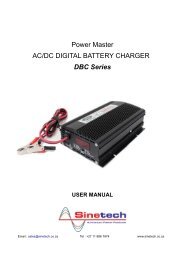
Overview of devicesSMA Solar Technology AG3 Overview of devices3.1 IdentificationYou can identify the Sunny Boy with the aid of the type label (see figure below). The type label isfound on the right-hand side of the housing (when viewed from the front). It contains informationregarding the device type, serial number, device-specific key data, the CE mark and contactinformation for SMA Solar Technology.The following is an example of a Sunny Boy <strong>3000</strong> type label.DevicetypeSMA Solar Technology AGwww.SMA.de<strong>SUNNY</strong> <strong>BOY</strong>Photovoltaic string inverterModelMade in GermanySerial No.SB <strong>3000</strong> 2000165874Series numberV DC maxV DC MPPI DC maxV AC nomf AC nomP AC nomI AC nom600 V268-480 V12 A230 V50/60 Hz2750 W12 Acos 1VDE 0126-1-1 (2.06)outdoorGÜTEZEICHENSolar*2000165874*10 SB25_30-IEN083212 <strong>Installation</strong> <strong>Guide</strong>
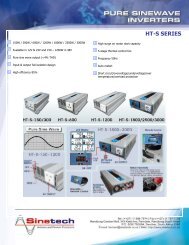
S2S1SMA Solar Technology AGOverview of devices3.2 Unit DescriptionThe following diagram gives a schematic overview of the various components and connection pointsinside the Sunny Boy with the cover removed:Varistors, section 7Communication terminalSocket for communication(RS485, radio), section 8Sunny DisplayOperating status LEDsABABCBAJumper slot forcommunicationPlug socket (AC), section5.2.1PE (protective earth) connector for coverTab for grounding the cable shield with RS485 communicationElectronic Solar Switch (ESS) socketPV input plugs (DC), section 5.2.2<strong>Installation</strong> <strong>Guide</strong> SB25_30-IEN083212 11
SMA SOLAR TECHNOLOGYOverview of devicesSMA Solar Technology AG3.3 Dimensions<strong>SUNNY</strong> <strong>BOY</strong>295 mm40 mm434 mm 214 mm12 SB25_30-IEN083212 <strong>Installation</strong> <strong>Guide</strong>
SMA Solar Technology AGOverview of devices3.4 Electronic Solar Switch (ESS)3.4.1 DesignThe Sunny Boy is equipped with the integrated electronic DC load-disconnecting switch ESS. Thisreliably prevents the arcing that usually occurs when disconnecting the inverter from the PV generator,which can cause personal injury and may damage the inverter connections. To access the DC inputplugs in order to safely disconnect the PV generator from the inverter, you only need to pull on a griphandle on the underside of the inverter.Disconnecting the inverter thus becomes a three-step process:1. Disconnecting the AC side2. Pulling off the Electronic Solar Switch handle3. Disconnecting the DC plug connectorsDANGER!Danger to life due to unsafe disconnection from the PV generator!• Safe disconnection from the PV generator is only guaranteed after removal of theElectronic Solar Switch, and of all DC plug connectors.DesignThe Electronic Solar Switch consists of a handle on theunderside of the inverter and an assembly inside theinverter.A handle is mounted on the underside of the inverterwhich covers the PV generators connectors.A plug is inside the handle. The Electronic Solar Switchsconnector is only visible once the handle has been pulled.The connector is fitted in the handle as a floatingconnector, so that the handle does not catch when beingpulled from the inverter.Electronic Solar Switch handlePlugNOTICE!The Electronic Solar Switch can be damaged if it is inserted incorrectly!• Do not tighten the connectors screws. Otherwise, safe disconnection can not beguaranteed.<strong>Installation</strong> <strong>Guide</strong> SB25_30-IEN083212 13
Overview of devicesSMA Solar Technology AG3.4.2 InspectionCheck the Electronic Solar Switch for wear before you attach it.To do this, check the metal tongues on the inside of the plug for brown discoloration.Metal tonguesIf at least one of the metal tongues is brown or fully burned off (see figure below), the Electronic SolarSwitch can no longer be guaranteed to function correctly.You must replace the handle of the Electronic Solar Switch before you can reactivate the Sunny Boy.Replacements for damaged Electronic Solar Switch handles are available from your dealer.Worn-out metal tongues14 SB25_30-IEN083212 <strong>Installation</strong> <strong>Guide</strong>
SMA Solar Technology AG<strong>Installation</strong> Requirements4 <strong>Installation</strong> RequirementsCheck that all of the requirements listed below are met before installing and commissioning the SunnyBoy.4.1 <strong>Installation</strong> LocationRequirementsThe Sunny Boy <strong>2500</strong> weighs 30 kg, the Sunny Boy <strong>3000</strong>weighs 32 kg. Take this weight into account whenchoosing the installation location and method ofinstallation.30/ 32 kgThe ambient temperature should be below + 40 °C at all times to guarantee optimaloperation.The Sunny Boy is designed for outdoor installation and should be installed in a place where it is notexposed to direct sunlight. An increased ambient temperature can reduce the yield of the PV system.Installing the unit in badly ventilated, warm indoor locations may also reduce yield.The Sunny Boy is designed to be mounted on a vertical wall. However, if absolutely necessary, theSunny Boy can be installed tilted back at a maximum angle of 45°. Vertical installation is preferablefor an optimum energy yield and maximum operational comfort.Never install the Sunny Boy horizontally or with a forward tilt.min. 45°Install the inverter vertically or tiltingbackward.Never install the inverter horizontally orso that it tilts forward.<strong>Installation</strong> <strong>Guide</strong> SB25_30-IEN083212 15
SMA SOLAR TECHNOLOGY<strong>SUNNY</strong> <strong>BOY</strong><strong>Installation</strong> RequirementsSMA Solar Technology AGWhen choosing the installation location, be sure to observe the following:WARNING!Dangerous Voltage!Unintentionally pulling out the DC plug connectors under load can damage the plugs andcould result in personal injury! Install the Sunny Boy in such a way that it is not possible(e.g. for children) to unplug the DC plug connector unintentionally.CAUTION!Danger of burn injuries due to hot housing parts!The temperature of the individual components in the housing, especially the heatsinks, canexceed 60 °C.• Do not touch the housing of the Sunny Boy during operation.• Mount the Sunny Boy in such a way that it cannot be touched inadvertently duringoperation.DANGER!Danger to life due to fire or explosion!Despite careful construction, a fire can occur with electrical devices.Do not install the Sunny Boy• on flammable construction materials,• in areas where highly flammable materials are stored,• in potentially explosive environments!When choosing the installation location, ensure there is enough space for heat to dissipate andenough space for pulling the Electronic Solar Switch handle! Under normal conditions, the followingrecommended values for the space to be kept clear around the Sunny Boy should be followed:DirectionSidesTopUnderneathFrontMinimum Clearances20 cm20 cm50 cm5 cm20cm20 cm 20 cm5cm50cm16 SB25_30-IEN083212 <strong>Installation</strong> <strong>Guide</strong>
SMA Solar Technology AG<strong>Installation</strong> RequirementsIn a living area, the unit should not be mounted onplasterboard walls or alike as otherwise audiblevibrations are likely to result.We recommend securing the unit to a solid surface.The Sunny Boy can make noises when in use which canbe seen as a nuisance when installed in a living area.4.2 PV Generator RequirementsThe Sunny Boy is designed to be connected to up to three strings (PV modules wired in series) havinga homogenous structure (modules of the same type, identical orientation and tilt).Sunny Design will assist you in the system design and checking of the string size for a given type ofinverter. Further information on Sunny Design is available at www.SMA.de.The unit has six DC plug connectors (two for each string) for connecting the PV generators. Theconnecting cables from the PV generators must also be fitted with this type of plug connector. A preassembledset for connecting the free cable ends from a string is available as an optional accessory.The SMA order codes for the various connectors are as follows:• Multi-Contact 3 mm: "SWR-MC"• Multi-Contact 4 mm: "MC-SET"• Tyco: "TYCO-SET"Limit values for DC inputMax. voltageMax. input current600 V (DC)12 A (DC)4.3 Low Voltage Grid (AC)The Sunny Boy must have a three-conductor connection to the grid (live (L), neutral (N), protectiveearth (PE)).The grid connection terminals on the AC connectionsocket included in the accessories kit can take wires witha cross-section of up to 2,5 mm². The accessories kit alsocontains a PG13.5 AC connection socket for connectingcables with a diameter between 9 mm and 13.5 mm,while the PG16 connection socket is used for cables witha diameter up to a maximum of 17 mm. For detailedCablediametero9 ... 17 mmWirecrosssectionmax. 2,5 mm²instructions, see sections „Connecting the AC Output with PG13.5“ (25) and „Connecting the ACOutput with PG16“ (27).<strong>Installation</strong> <strong>Guide</strong> SB25_30-IEN083212 17
SMA SOLAR TECHNOLOGY<strong>SUNNY</strong> <strong>BOY</strong><strong>Installation</strong> RequirementsSMA Solar Technology AGDANGER!Risk of lethal burns!We recommend using a 20 A line circuitbreaker to protect the power circuit. No loadsshould be connected to this power circuit.For optimum operation of the inverters, the grid impedance of the AC cable must not exceed 1 Ohm.This is necessary, amongst other things, for the correct operation of the impedance monitoring. Inaddition, we recommend dimensioning the cable cross-section so that output losses do not exceed1 % at nominal power. Output losses depending on the cable length and cross-section are shown inthe table below. Multi-wire cables with copper forward and return conductors are used.Line lossesRating for a line circuit breakerDetailed Information and examples concerning the rating of a line circuit breaker can befound in the Technical Information "line circuit breaker" in the download area of SMA SolarTechnology at www.SMA.de.The maximum cable lengths for the different cable cross-sections are as follows:Sunny Boy <strong>2500</strong> Sunny Boy <strong>3000</strong>Cable Cross-Section 1,5 mm² 2,5 mm² 2,5 mm²Max. length 9 m 15,5 m 12,5 mDo not use cables where losses will exceed 1.0 % !18 SB25_30-IEN083212 <strong>Installation</strong> <strong>Guide</strong>
SMA Solar Technology AG<strong>Installation</strong> RequirementsThe Sunny Boy is designed for operation on 220 - 240 V grids at a grid frequency of 50 / 60 Hz.When connecting an inverter to the public grid, follow the connection requirements of the local gridoperator.Voltage range(complying with DIN VDE 0126-1-1)Frequency range(complying with DIN VDE 0126-1-1)Voltage range (extended operating range)Frequency range (extended operating range)Limit values for AC output198 V ... 253 / 260 V a)47.55 Hz ... 50.2 Hz180 V ... 265 V45.5 Hz ... 54.5 Hz55.5 Hz ... 64.5 Hza) The Sunny Boy can feed into the public grid at a maximum output voltage of 260 V for brief periods. However, DINVDE 0126-1-1 stipulates that the average voltage over 10 minutes must not exceed 253 V. That means, if the gridvoltage is constantly 254 V (e.g.), the inverter disconnects itself from the grid. In this case, contact the local gridoperator for assistance.DIN VDE 0126-1-1 only applies in Germany. All other preset country values of your inverter can be found in thedownload area at www.SMA.de under Technical Description "Operating parameters" .<strong>Installation</strong> <strong>Guide</strong> SB25_30-IEN083212 19
SMA SOLAR TECHNOLOGYSU NY <strong>BOY</strong><strong>Installation</strong>SMA Solar Technology AG5 <strong>Installation</strong>5.1 MountingTo make the job easier, we recommend you use thesupplied wall bracket to mount the Sunny Boy. Forvertical installation and installation on solid concrete orblock walls, for example, you can fit the bracket using6 mm x 50 mm hexagon bolts to DIN 571 standard,stainless steel type, and with wall anchors type SX 8.When selecting the mounting materials, be sure to takeinto account the weight of the Sunny Boy (Sunny Boy<strong>2500</strong> 30 kg; Sunny Boy <strong>3000</strong> 32 kg).If you do not want to use the supplied wall bracket as a template, observe the dimensions shown inthe illustration below. The procedure for mounting the inverter using the wall bracket is described onthe following pages.117 mm108,75 mm217,5 mm112 mm182 mm179,5 mm20 SB25_30-IEN083212 <strong>Installation</strong> <strong>Guide</strong>
SMA Solar Technology AG<strong>Installation</strong>1. Mount the wall bracket (1). To mark the positions todrill the holes, you can use the wall bracket as adrilling template.2. Now hang the Sunny Boy onto the wall bracket (2)using its upper mounting plate so that it cannot bemoved sideways.3. Secure the Sunny Boy in position by screwing thesupplied M6x10 bolt into the central threaded holeat the bottom of the bracket (3).4. Make sure that the Sunny Boy is positionedsecurely on the bracket.2315.2 Electrical <strong>Installation</strong>WARNING!Make sure to check the polarity of the strings before connecting them.The wiring for the Sunny Boy is shown schematically in the following figure:16ABAC connection, max. 2.5 mm²String 1String 2String 3<strong>Installation</strong> <strong>Guide</strong> SB25_30-IEN083212 21
<strong>Installation</strong>SMA Solar Technology AGView from belowElectronic Solar Switch (ESS)socketAC plug for gridconnectionPlug connector forconnection of thesolar modulesCable openings foroptional communicationvia RS485 or radio(PG16)22 SB25_30-IEN083212 <strong>Installation</strong> <strong>Guide</strong>
SMA Solar Technology AG<strong>Installation</strong>5.2.1 Connecting the AC outputDANGER!Danger to life due to high voltages in the Sunny Boy!• Before you connect the power line to the AC connection socket, make sure that novoltage is present at the cable.A round plug connector system is used, which allows various cable diameters to be used in the cableoutlet. For this reason, the accessories kit includes a PG13.5 pressure screw and a PG16 pressurescrew. Check which screw fitting is the right one for your AC cable.To connect up the AC output, follow these steps:1. Check the grid voltage. If this is higher than 253 V, the Sunny Boy will not be fully operational.In this case, contact the local grid operator for assistance.2. Isolate the grid connection (switch the line circuitbreaker to its "Off" position), make sure it cannot be Off!switched back on, and test to make sure no voltageis present.1. 2. 3.3. Peel off approximately 30 mm of the cable jacket.Shorten L and N by 5 mm.approx.25 mm4. Strip approximately 4 mm of the cables insulation.approx.4 mm<strong>Installation</strong> <strong>Guide</strong> SB25_30-IEN083212 23
<strong>Installation</strong>SMA Solar Technology AG5. Now take the AC connection socket parts from the accessories kit and connect up the cable,with shielding and insulation stripped, as described on the following pages.Cord gripfor PG13.5Sealing ringfor PG13.5Pressure screw forPG13.5Threaded sleeveSocket elementPG16 pressure screw for largecable cross-sections24 SB25_30-IEN083212 <strong>Installation</strong> <strong>Guide</strong>
SMA Solar Technology AG<strong>Installation</strong>Connecting the AC Output with PG13.5To connect a cable with a maximum diameter of 13.5 mm, proceed as follows.1. Press the sealing ring (1) into the cord grip (2).(1)2. Now slide the pressure screw (3) over the cablefirst of all, followed by the cord grip with the sealing ring (4) in it. Now slide the threaded sleeve(5) over the cable.(5)(4)(3)(2)3. Now connect the individual conductors to the socket element in sequence.– Protective earth PE (green/yellow) to the screwNterminal with the earth sign.PE– Neutral conductor N (blue) to screw terminal 1.– Live L (brown or black) to screw terminal 2.– Terminal 3 remains unused.1L234. Make sure the wires (6) are securely connected.(6)<strong>Installation</strong> <strong>Guide</strong> SB25_30-IEN083212 25
<strong>Installation</strong>SMA Solar Technology AG5. Now screw the threaded sleeve (7) onto the socket element (8) and tighten it.(8)(7)6. Now screw the pressure screw (9) into thethreaded sleeve (10) and tighten it. The cord gripwith the sealing ring is pressed into the threadedsleeve and can no longer be seen.(10)(9)The AC connection socket is now fully assembled.If you are not going to connect up the Sunny Boy immediately, close the socket element using the capsupplied in the accessories kit.If the Sunny Boy is already installed, you can now connect up the fully assembled AC connectionsocket to the flange plug on the Sunny Boy. To do this, remove the protective cap from the flange plugon the Sunny Boy. Firmly tighten the threaded ring on the AC connection socket to the flange plug toseal the connection and secure it.DANGER!Danger to life due to high voltages in the Sunny Boy!Do not switch the line circuit breaker on yet!• The Sunny Boy may only be connected to the AC grid once the PV strings areconnected and the device is securely closed.26 SB25_30-IEN083212 <strong>Installation</strong> <strong>Guide</strong>
SMA Solar Technology AG<strong>Installation</strong>Connecting the AC Output with PG16To connect a cable with a diameter between 13.5 mm and 16 mm, proceed as follows.1. First of all, slide the pressure screw with the PG16 screw fitting (1) onto the cable. Now slidethe threaded sleeve (2) over the cable.(2)(1)2. Now connect the individual wires to the socket element in sequence.– Protective earth PE (green/yellow) to the screwterminal with the earth sign.PE– Neutral conductor N (blue) to screw terminal 1.– Live L (brown or black) to screw terminal 2.– Terminal 3 remains unused.N1L233. Make sure the wires (3) are securely connected.(3)4. Now screw the threaded sleeve (4) onto the socket element (5) and tighten it.(5)(4)<strong>Installation</strong> <strong>Guide</strong> SB25_30-IEN083212 27
<strong>Installation</strong>SMA Solar Technology AG5. Now screw the pressure screw (6) into thethreaded sleeve (7) and tighten it.6. Firmly tighten the screw fitting to provide sealingand provide strain relief.(7)(6)The AC connection socket is now fully assembled.If you are not going to connect up the Sunny Boy immediately, close the socket element using the capsupplied in the accessories kit.If the Sunny Boy is already installed, you can now connect up the fully assembled AC connectionsocket to the flange plug on the Sunny Boy. To do this, remove the protective cap from the flange plugon the Sunny Boy. Firmly tighten the threaded ring on the AC connection socket to the flange plug toseal the connection and secure it.DANGER!Danger to life due to high voltages in the Sunny Boy!Do not switch the line circuit breaker on yet!• The Sunny Boy may only be connected to the AC grid once the PV strings areconnected and the device is securely closed.28 SB25_30-IEN083212 <strong>Installation</strong> <strong>Guide</strong>
SMA Solar Technology AG<strong>Installation</strong>5.2.2 PV String (DC) ConnectionTo connect up the input, follow these steps:1. Remove the Electronic Solar Switch on theunderside of the Sunny Boy.2. Make sure the PV generator connectors have theright polarity and do not exceed the maximumstring voltage of 600 V (DC). See also section4.2 „PV Generator Requirements“ (17).WARNING!The Sunny Boy could be irreparably damaged by overvoltage!If the voltage of the solar modules exceeds the maximum input voltage of the Sunny Boy,it could be irreparably damaged by overvoltage. All warranty claims become void.• Do not connect strings to the Sunny Boy with open circuit voltage greater than themaximum input voltage of the Sunny Boy.• Check the system design.3. Taking one DC plug connector at a time, measurethe direct current voltage between one DC plugconnector of a string and ground potential.4. If the measured voltages are constant and theirtotal is roughly the same as the open circuit voltageof the string, then there is a ground fault in thisstring. Its approximate location can be deducedfrom the relationships between the voltages.PEWARNING!Do not connect strings to the Sunny Boy that contain a ground fault until you have fixed theground fault in the PV generator!<strong>Installation</strong> <strong>Guide</strong> SB25_30-IEN083212 29
<strong>Installation</strong>SMA Solar Technology AG5. Repeat points 3 and 4 for each string.6. Connect up the faultless PV generator strings to theinverter.7. Close the unused DC input sockets with the capsincluded in the delivery.+ + + - - -8. Reinsert the handle of the Electronic Solar Switch inthe socket on the underside of the Sunny Boy.NOTICE!The Electronic Solar Switch can be damaged if it is inserted incorrectly!• The handle must be firmly attached to the socket of the Electronic Solar Switch andrest against the housing.• Check that the handle is positioned correctly before recommissioning the inverter.30 SB25_30-IEN083212 <strong>Installation</strong> <strong>Guide</strong>
SMA SOLAR TECHNOLOGY<strong>SUNNY</strong> <strong>BOY</strong>SMA Solar Technology AG<strong>Installation</strong>5.3 CommissioningYou can commission the Sunny Boy when:• the housing cover is securely screwed on• the Electronic Solar Switch is securely attached• the AC (grid) cable is connected correctly.• the DC cables (PV strings) are fully connected and the unused DC plug connectors on thebottom of the housing are closed using the protective caps.Commissioning procedure1. Switch the line circuit breaker to the "On" position.On2. Now look at the LED display and consult the tableon the following page to check whether the SunnyBoy is in a fault-free and expedient operatingmode. If this is the case, commissioning wassuccessfully completed.NOLOGYOYOperation (green)Ground fault (red)Fault (yellow)NOTICE!Excessive DC input voltage can destroy the Sunny Boy!• Disconnect the grid voltage and the PVgenerator if after a short time the bottomyellow LED flashes four times at intervalsof one second and the display shows themessage on the right.Check the string voltages again to make sure they are within the limits stated in section 4.2 „PVGenerator Requirements“ (17). If the input voltage is too high, contact the planner / installer of thePV generator for assistance.If despite checking the string voltages the LED signal occurs again when the PV generator is connectedto the Sunny Boy, disconnect the PV generator from the Sunny Boy again and contact SMA ServiceLine (see section 10 „Contact“ (49)).<strong>Installation</strong> <strong>Guide</strong> SB25_30-IEN083212 31
<strong>Installation</strong>SMA Solar Technology AG. Green Red Yellow StatusGlows continuously is not glowing is not glowing OK (feeding operation)glows continuously is not glowing faultglows continuously OK (initialization)Flashes quickly is not glowing is not glowing OK (stop)(3 x per second) glows continuously is not glowing faultBlinks slowly(1 x per second)Briefly goes out(approx. 1x persecond)is not glowing is not glowing OKmaintenance, grid monitoringglows continuously is not glowing faultis not glowing is not glowing OK (derating)glows continuously is not glowing faultIs not glowing is not glowing is not glowing OK (night shutdown)glowing/blinking faultglows continuously is not glowing faultglowing/blinking faultFor a detailed description of the failure messages and their causes, see the user manual.32 SB25_30-IEN083212 <strong>Installation</strong> <strong>Guide</strong>
SMA Solar Technology AGOpening and Closing the Sunny Boy6 Opening and Closing the Sunny Boy6.1 Safety instructionsIf you need to open the device for whatever reason, pay attention to section 2.5 „Safetyinstructions“ (8).DANGER!Danger to life due to high voltages in the Sunny Boy!• Before working on the Sunny Boy with the cover removed, the AC and DC voltagesmust therefore be disconnected from the Sunny Boy and the capacitors must bedischarged (wait for 15 minutes after isolating the AC and DC voltages).NOTICE!Electrostatic discharges can damage the Sunny Boy!Electronic components are susceptible to electrostatic charge.• Discharge any electrostatic charge by touching the grounded housing while handlingany electronic component.<strong>Installation</strong> <strong>Guide</strong> SB25_30-IEN083212 33
Opening and Closing the Sunny BoySMA Solar Technology AG6.2 Opening the Sunny BoyFollow the sequence described below and all safety instructions in section 6.1 „Safetyinstructions“ (33)!DANGER!Danger to life due to high voltages in the Sunny Boy!Before you open the Sunny Boy:• Switch off the line circuit breaker and secure it to prevent it being reactivated.1. Pull the handle of the Electronic Solar Switch off the Sunny Boy.Be sure to pull the handle downwards and slightly towards the wall. There is a contact in themiddle that automatically starts the switching process when the handle is pulled.2. Directly after pulling off the Electronic Solar Switch, pull out the DC plug connectors from theSunny Boy.DANGER!Danger to life due to high voltages in the Sunny Boy!• Wait 15 minutes for the capacitors inside the Sunny Boy to discharge!3. Remove the four screws from the housing cover and pull the cover forward smoothly.4. Remove the PE connection from the cover.5. Loosen the locking on the PE connectors on the cover when you remove them.34 SB25_30-IEN083212 <strong>Installation</strong> <strong>Guide</strong>
SMA Solar Technology AGOpening and Closing the Sunny Boy6.3 Closing the Sunny BoyFollow the sequence described below and all safety instructions in section 6.1 „Safetyinstructions“ (33)!1. Reconnect the protective earth (PE) to the housing cover.2. Secure the housing cover of the Sunny Boy by evenly tightening the four screws.3. Connect the PV generator by reconnecting the DC plug connectors of the Sunny Boy with thoseof the strings.4. Check the Electronic Solar Switch for wear, as described in section 3.4.2 „Inspection“ (14).5. Reinsert the handle of the Electronic Solar Switch in the socket on the underside of the SunnyBoy.NOTICE!The Electronic Solar Switch can be damaged if it is inserted incorrectly!The Electronic Solar Switch can be damaged if it has not been attached properly.• The handle must be firmly attached to the socket of the Electronic Solar Switch andrest against the housing.• Check that the handle is positioned correctly before recommissioning the inverter.6. Switch the line circuit breaker to the "On" position.7. Check whether the LED display on the Sunny Boy indicates that the device is functioningcorrectly.<strong>Installation</strong> <strong>Guide</strong> SB25_30-IEN083212 35
Replacing the VaristorsSMA Solar Technology AG7 Replacing the VaristorsThe Sunny Boy is a complex high-technology device. As a result, the possibilities for fixing faults onsite are limited to just a few items. Do not attempt to carry out repairs other than those described here.Use the SMA Solar Technology 24-hour replacement service and repair service instead.If the red LED on the status display shines continuously during operation, you should first of all makesure that there is no ground fault in the PV generator.1. Disconnect the Sunny Boy from the low voltage grid(switch the line circuit breaker to its "off" position orpull out the AC plug). Make sure the grid cannot be Off!inadvertently reconnected.You must make sure that no voltage is present at theAC output before opening the Sunny Boy.1. 2. 3.2. Pull the handle of the Electronic Solar Switch off theSunny Boy.3. Disconnect the DC plug connectors for all strings.+ + + - - -4. Taking one DC plug connector at a time, measurethe voltages between one DC plug connector of astring and ground potential.PE36 SB25_30-IEN083212 <strong>Installation</strong> <strong>Guide</strong>
SMA Solar Technology AGReplacing the VaristorsDANGER!Risk of lethal electric shock!In case of a ground fault, the PV generator may carry high voltages.• Do not touch the frame of the PV generator.• Do not touch PE.• Wait until no voltage can be measured.• Do not connect strings with ground faults to the Sunny Boy.5. If the measured voltages are constant and their total is roughly the same as the open circuitvoltage of the string, then there is a ground fault in this string. Its approximate location can bededuced from the relationships between the voltages.Repeat step 4 for each string.If you found a ground fault, it is probably not necessary to replace the varistors. Instead, makesure the ground fault is fixed. Generally the PV generator‘s installer should be hired for this job.In this case continue as described under point 9, but without reconnecting the faulty string!Protect its DC plug against accidental touch or contact (e.g. by fitting the protective caps orusing sufficient high-voltage insulating tape).If you did not find any ground fault in the PV generators, it is likely that one of the thermallymonitored varistors has lost its protective function. These components are wearing parts. Theirfunctioning diminishes with age or following repeated responses as a result of overvoltages.You can now check these varistors in the following way, paying attention to the safetyinstructions in section 2.5 „Safety instructions“ (8):6. Remove the screws securing the cover and remove the cover from the Sunny Boy. Disconnectthe PE connection from the cover. Make sure that no voltage is present.7. Use a continuity tester to check all the varistors and see if there is a conducting connectionbetween connectors 2 and 3. If there is no connection, then that varistor is not working. Thepositions of the varistors in the Sunny Boy can be seen in the figure in section 3.2 „UnitDescription“ (11).<strong>Installation</strong> <strong>Guide</strong> SB25_30-IEN083212 37
Replacing the VaristorsSMA Solar Technology AG8. Replace the varistor concerned with a new one asshown in the illustration to the right. Ensure thevaristor is installed the right way round! If you donot receive a special tool for operating the terminalclamps together with your replacement varistors,please contact SMA Solar Technology. As analternative, the terminal contacts can be operatedusing a suitable screwdriver. Since the failure ofone varistor is generally due to factors that affect allvaristors in a similar way (temperature, age,inductive overvoltages), it is highly recommendedthat you replace both varistors, not just the one thatis obviously defective. The varistors are speciallymanufactured for use in the Sunny Boy and are notcommercially available. They must be ordereddirectly from SMA Solar Technology (SMA ordercode: "SB-TV4").3 21Insert the special tool toopen the terminal clampRemove the varistorThe pole with thesmall loop (crimp)must be fitted toterminal 1 whenreplacing the varistor.If no replacement varistors are available onsite, the Sunny Boy can be temporarily runwithout them. To do this, remove the varistorsyou identified as being faulty as describedabove and in their place, bridge the terminals2 and 3 with a length of wire.3 213 21NOTICE!The Sunny Boy could be irreparably damaged by overvoltage!If varistors are missing, the Sunny Boy is no longer protected against overvoltages.• The Sunny Boy must not be operated without varistors in systems with a high risk ofovervoltages.• Replacement varistors should be obtained as soon as possible.9. Reconnect the PE connection on the cover and close the Sunny Boy.10. Connect up the faultless PV generator strings to theinverter.11. Close the unused DC input sockets with the capsincluded in the delivery.+ + + - - -38 SB25_30-IEN083212 <strong>Installation</strong> <strong>Guide</strong>
SMA SOLAR TECHNOLOGY<strong>SUNNY</strong> <strong>BOY</strong>SMA Solar Technology AGReplacing the Varistors12. Reinsert the handle of the Electronic Solar Switch inthe socket on the underside of the Sunny Boy.NOTICE!The Electronic Solar Switch can be damaged if it is inserted incorrectly!The Electronic Solar Switch can be damaged if it has not been attached properly.• The handle must be firmly attached to the socket of the Electronic Solar Switch andrest against the housing.• Check that the handle is positioned correctly before recommissioning the inverter.13. Switch the line circuit breaker to the "On" position.On14. Now check whether the LED display on the SunnyBoy indicates that the device is functioningcorrectly.NOLOGYOYOperation (green)Ground fault (red)Fault (yellow)If no ground fault and no defective varistor were found, there is probably a fault in the Sunny Boy. Inthis case, contact the SMA Service Line to discuss what to do next.<strong>Installation</strong> <strong>Guide</strong> SB25_30-IEN083212 39
The communication interfaceSMA Solar Technology AG8 The communication interfaceThe communication interface is used for communication with special data acquisition devices or a PCwith corresponding software.See the communication interface documentation for a detailed wiring diagram.This section describes how to install the communication module in the Sunny Boy.<strong>Installation</strong> procedureThe letters in brackets refer to the figure on the next page.1. Open the Sunny Boy as described in Section 6.2 .WARNING!Electrostatic discharges can damage the communication interface!• Do not touch components connections and plug contacts.• Ground yourself before removing the communication interface from the packagingby touching the PE or a non-coated part of the housing.2. Thread the cable through one of the cable feed-throughs (A) on the Sunny Boy. Use the righthandhousing feed-through for the Radio Piggy-Back.WARNING!Danger to life through high voltage if there is a fault with the communicationcable.• Pull the silicone tube over the cable.The silicon tube must completely cover the communication cable inside the housing.3. If the connection plan of the communication device indicates it as necessary:– ground the communication cable at the tab (C) or– use the provided cable shield on its screwing device (F) for the communication interface.4. Install the communication cable (B) as described in the following figure.5. Connect the communication wires to the screw terminal strip (D) as described in the connectionplan of the communication device.6. Connect the jumpers (E) if the connection plan of the communication device indicates this asnecessary.A detailed description of the jumper functions can be found in the communication devicemanual.7. Plug the communication interface to the left of the interface port (F).8. Close the Sunny Boy as described in section 6.3 .40 SB25_30-IEN083212 <strong>Installation</strong> <strong>Guide</strong>
SMA Solar Technology AGThe communication interfaceFD2357E2357PEC B AABCDEFHousing feed-through in the base of the Sunny BoyCable route (gray surface)Tab for grounding the cable shieldScrew terminals for connection of the communication wiresJumper slotInterface port<strong>Installation</strong> <strong>Guide</strong> SB25_30-IEN083212 41
Technical dataSMA Solar Technology AG9 Technical data9.1 Sunny Boy <strong>2500</strong>9.1.1 PV Generator Connection DataDescription Unit SettingMax. input voltage U DC max 600 V a)Input voltage, MPP range U PV 224 V ... 480 VMax. input current I PV max 12 AMax. input power P DC 2700 WRecommended total generator power<strong>3000</strong> Wp (for Central Europe)All-pole disconnection unit on the DC inputsideOvervoltage protectionElectronic Solar Switch (ESS)DC plug connectorthermally monitored varistorsVoltage ripple U pp < 10 % of the input voltageInsulation protectionground fault monitoring(Riso > 1 MOhm)Operating internal consumption< 7 W (standby)Reverse polarity protectionvia short-circuit diodea) The maximum open circuit voltage, which can occur at a cell temperature of -10 °C, may not exceed the maximum inputvoltage.42 SB25_30-IEN083212 <strong>Installation</strong> <strong>Guide</strong>
SMA Solar Technology AGTechnical data9.1.2 Grid Connection DataDescription Unit SettingNominal output power P ACnom 2300 WPeak output power P AC, max <strong>2500</strong> WNominal output current I AC, nom 10 AMax. output current I AC, max 12.5 AMax. fuse protection20 AHarmonic distortion of output current K IAC < 3 %(at K Ugrid < 2 %, P AC > 0.5 P AC nom )Short-circuit proofinggrid-side via current regulationOperating range, grid voltage U AC 180 ... 265 V ACOperating range, grid frequency f AC 47,55 ... 50.2 HzAll-pole disconnection unit on grid sideAutomatic disconnection device(SMA grid guard 2),double implementationPower factor (at nominal output power) cos phi 1Overvoltage categoryIIITest voltage (DC) 1.95 kV (1 s routine testing /5 s type testing)Test surge voltage4 kV (serial interface: 6 kV)Operating consumption in night mode0.25 W<strong>Installation</strong> <strong>Guide</strong> SB25_30-IEN083212 43
Technical dataSMA Solar Technology AG9.2 Sunny Boy <strong>3000</strong>9.2.1 PV Generator Connection DataDescription Unit SettingMax. input voltage U DC max 600 V a)Input voltage, MPP range U PV 268 V ... 480 VMax. input current I PV max 12 AMax. input power P DC 3200 WRecommended total generator power3600 Wp (for Central Europe)All-pole disconnection unit on the DC inputsideOvervoltage protectionElectronic Solar Switch (ESS)DC plug connectorthermally monitored varistorsVoltage ripple U pp < 10 % of the input voltageInsulation protectionground fault monitoring(Riso > 1 MOhm)Operating internal consumption< 7 W (standby)Reverse polarity protectionvia short-circuit diodea) The maximum open circuit voltage, which can occur at a cell temperature of -10 °C, may not exceed the maximum inputvoltage.44 SB25_30-IEN083212 <strong>Installation</strong> <strong>Guide</strong>
SMA Solar Technology AGTechnical data9.2.2 Grid Connection DataDescription Unit SettingNominal output power P ACnom 2750 WPeak output power P AC, max <strong>3000</strong> WNominal output current I AC, nom 12 AMax. output current I AC, max 15 AMax. fuse protection20 AHarmonic distortion of output current K IAC < 3 %(at K U grid < 2 %, P AC > 0.5 P AC nom )Short-circuit proofinggrid-side via current regulationOperating range, grid voltage U AC 180 ... 265 V ACOperating range, grid frequency f AC 47,55 ... 50.2 HzAll-pole disconnection unit on grid sideautomatic disconnection device(SMA grid guard 2),double implementationPower factor (at nominal output power) cos phi 1Overvoltage categoryIIITest voltage (DC) 1.95 kV (1 s routine testing /5 s type testing)Test surge voltage4 kV (serial interface: 6 kV)Operating consumption in night mode0.25 W<strong>Installation</strong> <strong>Guide</strong> SB25_30-IEN083212 45
Technical dataSMA Solar Technology AG9.3 Device DescriptionFor a detailed description of the device, see the user manual.General dataEC Declaration of ConformityProtection rating in accordance with DIN EN 60529Dimensions (W x H x D)WeightCommunication InterfaceData transmission via separate data cableWireless data transmissionYou can download the EC Declaration ofConformity in the download area atwww.SMA.de under Certificate.IP65approx. 434 mm x 295 mm x 214 mmSunny Boy <strong>2500</strong>: approx. 30 kgSunny Boy <strong>3000</strong>: approx. 32 kgoptional, RS485,galvanically isolatedoptionalElectronic Solar Switch (ESS)Electrical service life(in case of a short circuit, with a nominal current of 30 A):Maximum switching currentMaximum switching voltageMaximum PV powerProtection rating when pluggedProtection rating when unpluggedmin. 50 switching processes30 A800 Vapprox. 10 kWIP65IP2146 SB25_30-IEN083212 <strong>Installation</strong> <strong>Guide</strong>
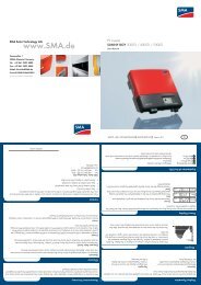
SMA Solar Technology AGTechnical data9.3.1 Efficiency of the Sunny Boy <strong>2500</strong>EfficiencyMax. efficiency η max 94,1 %CEC rebate efficiency η euro 93,2 %The efficiency of the Sunny Boy <strong>2500</strong> depends mainly on the input voltage of the connected PVstrings. The lower the input voltage, the higher the efficiency.98Overall efficiency [%]969492908886euro [%]9490300 400 500U MPP [V]300 V400 V500 VSunny Boy <strong>2500</strong>50010001500 2000 <strong>2500</strong>Output power [W]<strong>Installation</strong> <strong>Guide</strong> SB25_30-IEN083212 47
Technical dataSMA Solar Technology AG9.3.2 Efficiency of the Sunny Boy <strong>3000</strong>EfficiencyMax. efficiency η max 95 %CEC rebate efficiency η euro 93,6 %The efficiency of the Sunny Boy <strong>3000</strong> depends mainly on the input voltage of the connected PVstrings. The lower the input voltage, the higher the efficiency.9896Overall efficiency [%]94929088300 V400 V480 Veuro [%]94,093,593,092,586300 400 480U MPP [V]Sunny Boy <strong>3000</strong>50010001500 2000 <strong>2500</strong> <strong>3000</strong>Output power [W]48 SB25_30-IEN083212 <strong>Installation</strong> <strong>Guide</strong>
SMA Solar Technology AGContact10 ContactIf you have technical problems concerning our products, please contact the SMA Service Line. Werequire the following information in order to provide you with the necessary assistance:• Inverter type• Type and number of modules connected• Communication method• Serial number of the Sunny Boy• Blink code or display of the Sunny BoySMA Solar Technology AGSonnenallee 134266 Niestetal, GermanyTel.: +49 (561) 95 22 - 499Fax: +49 (561) 95 22 - 4699Serviceline@SMA.dewww.SMA.de<strong>Installation</strong> <strong>Guide</strong> SB25_30-IEN083212 49
ContactSMA Solar Technology AG50 SB25_30-IEN083212 <strong>Installation</strong> <strong>Guide</strong>
SMA Solar Technology AGLegal RestrictionsThe information contained in this document is the property of SMA Solar Technology AG. Publishing its content, either partially orin full, requires the written permission of SMA Solar Technology AG. Any internal company copying of the document for thepurposes of evaluating the product or its correct implementation is allowed and does not require permission.Exclusion of liabilityThe general terms and conditions of delivery of SMA Solar Technology AG shall apply.The content of these documents is continually checked and amended, where necessary. However, discrepancies cannot beexcluded. No guarantee is made for the completeness of these documents. The latest version is available online at www.SMA.deor from the usual sales channels.Guarantee or liability claims for damages of any kind are excluded if they are caused by one or more of the following:• Damages during transportation• Improper or inappropriate use of the product• Operating the product in an unintended environment• Operating the product whilst ignoring relevant, statutory safety regulations in the deployment location• Ignoring safety warnings and instructions contained in all documents relevant to the product• Operating the product under incorrect safety or protection conditions• Altering the product or supplied software without authority• The product malfunctions due to operating attached or neighboring devices beyond statutory limit values• In case of unforeseen calamity or force majeureThe use of supplied software produced by SMA Solar Technology AG is subject to the following conditions:• SMA Solar Technology AG rejects any liability for direct or indirect damages arising from the use of software developed bySMA Solar Technology AG. This also applies to the provision or non-provision of support activities.• Supplied software not developed by SMA Solar Technology AG is subject to the respective licensing and liability agreementsof the manufacturer.SMA Factory WarrantyThe current guarantee conditions come enclosed with your device. These are also available online at www.SMA.de and can bedownloaded or are available on paper from the usual sales channels if required.TrademarksAll trademarks are recognized even if these are not marked separately. Missing designations do not mean that a product or brandis not a registered trademark.SMA Solar Technology AGSonnenallee 134266 NiestetalGermanyTel. +49 561 9522-0Fax +49 561 9522-100www.SMA.deE-Mail: info@SMA.de© 2004 to 2008 SMA Solar Technology AG. All rights reserved<strong>Installation</strong> <strong>Guide</strong> SB25_30-IEN083212 51
SMA Solar Technology AGwww.SMA.deSonnenallee 134266 Niestetal, GermanyTel.: +49 561 9522 4000Fax: +49 561 9522 4040E-Mail: Vertrieb@SMA.deFreecall: 0800 <strong>SUNNY</strong><strong>BOY</strong>Freecall: 0800 78669269