RF01 Universal ISM Band FSK Receiver
RF01 Universal ISM Band FSK Receiver
RF01 Universal ISM Band FSK Receiver
- No tags were found...

You also want an ePaper? Increase the reach of your titles
YUMPU automatically turns print PDFs into web optimized ePapers that Google loves.
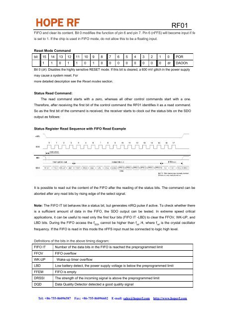
<strong>RF01</strong>FIFO and clear its content. Bit 0 modifies the function of pin 6 and pin 7. Pin 6 (nFFS) will become input if feis set to 1. If the chip is used in FIFO mode, do not allow this to be a floating input.Reset Mode Commandbit 15 14 13 12 11 10 9 8 7 6 5 4 3 2 1 0 POR1 1 0 1 1 0 1 0 0 0 0 0 0 0 0 dr DAOOhBit 0 (dr): Disables the highly sensitive RESET mode. If this bit is cleared, a 600 mV glitch in the power supplymay cause a system reset. Formore detailed description see the Reset modes section.Status Read Command:The read command starts with a zero, whereas all other control commands start with a one.Therefore, after receiving the first bit of the control command the <strong>RF01</strong> identifies it as a read command.So as the first bit of the command is received, the receiver starts to clock out the status bits on the SDOoutput as follows:Status Register Read Sequence with FIFO Read ExampleIt is possible to read out the content of the FIFO after the reading of the status bits. The command can beaborted after any read bits by rising edge of the select signal.Note: The FIFO IT bit behaves like a status bit, but generates nIRQ pulse if active. To check whether thereis a sufficient amount of data in the FIFO, the SDO output can be tested. In extreme speed criticalapplications, it can be useful to read only the first four bits (FIFO IT -LBD) to clear the FFOV, WK-UP, andLBD bits. During the FIFO access the f SCKcannot be higher than f ref/4, where f refis the crystal oscillatorfrequency. If the FIFO is read in this mode the nFFS input must be connected to logic high level.Definitions of the bits in the above timing diagram:FIFO IT Number of the data bits in the FIFO is reached the preprogrammed limitFFOV FIFO overflowWK-UP Wake-up timer overflowLBD Low battery detect, the power supply voltage is below the preprogrammed limitFFEM FIFO is emptyDRSSI The strength of the incoming signal is above the preprogrammed limitDQD Data Quality Detector detected a good quality signalTel: +86-755-86096587 Fax: +86-755-86096602 E-mail: sales@hoperf.com http://www.hoperf.com