enidine
enidine
enidine
- No tags were found...

You also want an ePaper? Increase the reach of your titles
YUMPU automatically turns print PDFs into web optimized ePapers that Google loves.
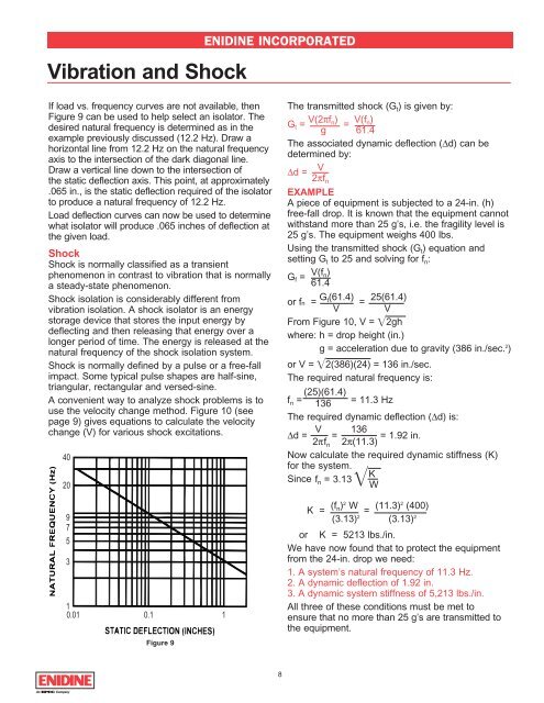
Vibration and ShockENIDINE INCORPORATEDIf load vs. frequency curves are not available, thenFigure 9 can be used to help select an isolator. Thedesired natural frequency is determined as in theexample previously discussed (12.2 Hz). Draw ahorizontal line from 12.2 Hz on the natural frequencyaxis to the intersection of the dark diagonal line.Draw a vertical line down to the intersection ofthe static deflection axis. This point, at approximately.065 in., is the static deflection required of the isolatorto produce a natural frequency of 12.2 Hz.Load deflection curves can now be used to determinewhat isolator will produce .065 inches of deflection atthe given load.ShockShock is normally classified as a transientphenomenon in contrast to vibration that is normallya steady-state phenomenon.Shock isolation is considerably different fromvibration isolation. A shock isolator is an energystorage device that stores the input energy bydeflecting and then releasing that energy over alonger period of time. The energy is released at thenatural frequency of the shock isolation system.Shock is normally defined by a pulse or a free-fallimpact. Some typical pulse shapes are half-sine,triangular, rectangular and versed-sine.A convenient way to analyze shock problems is touse the velocity change method. Figure 10 (seepage 9) gives equations to calculate the velocitychange (V) for various shock excitations.4020975310.01 0.1 1Figure 9The transmitted shock (G t ) is given by:G t = V(2πf n) =V(f n )ig 61.4The associated dynamic deflection (∆d) can bedetermined by:∆d =V2πf nEXAMPLEA piece of equipment is subjected to a 24-in. (h)free-fall drop. It is known that the equipment cannotwithstand more than 25 g’s, i.e. the fragility level is25 g’s. The equipment weighs 400 lbs.Using the transmitted shock (G t ) equation andsetting G t to 25 and solving for f n :G f = V(f n)61.4or fn = G t(61.4) =25(61.4)V VFrom Figure 10, V = 2ghwhere: h = drop height (in.)g = acceleration due to gravity (386 in./sec. 2 )or V = 2(386)(24) = 136 in./sec.The required natural frequency is:(25)(61.4)f n = 136 = 11.3 HzThe required dynamic deflection (∆d) is:V 136∆d = = = 1.92 in.2πf n 2π(11.3)Now calculate the required dynamic stiffness (K)for the system.KSince f n = 3.13 WK = (f n) 2 W =(11.3) 2 (400)(3.13) 2 (3.13) 2or K = 5213 lbs./in.We have now found that to protect the equipmentfrom the 24-in. drop we need:1. A system’s natural frequency of 11.3 Hz.2. A dynamic deflection of 1.92 in.3. A dynamic system stiffness of 5,213 lbs./in.All three of these conditions must be met toensure that no more than 25 g’s are transmitted tothe equipment.8