Create successful ePaper yourself
Turn your PDF publications into a flip-book with our unique Google optimized e-Paper software.
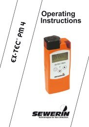
<strong>Operating</strong><strong>Instructions</strong>
Measurable success by Sewerin equipmentCongratulations.You have chosen a quality instrument manufactured by HermannSewerin GmbH.Our equipment will provide you with the highest standards of performance,safety and efficiency. They correspond with the national andinternational guide-lines.Please read and understand the following operating instructions beforeusing the equipment; they will help you to use the instrument quickly andcompetently. If you have any queries we are available to offer adviceand assistance at any time.YoursHermann Sewerin GmbHRobert-Bosch-Straße 333334 Gütersloh, GermanyTel.: +49 5241 934-0Fax: +49 5241 934-444www.sewerin.cominfo@sewerin.comSewerin LtdHertfordshireUKPhone: +44 1462-634363www.sewerin.co.ukinfo@sewerin.co.ukSEWERIN Sarl17, rue Ampère - BP 21167727 HOERDT CEDEX, FranceTél. : +33 3 88 68 15 15Fax : +33 3 88 68 11 77www.sewerin.frsewerin@sewerin.frSewerin USA, LLC13551 W. 43rd Drive, Unit RGolden, CO 80403-7272Phone: +1 303-424-3611Fax: +1 303-420-0033www.sewerin.netjerry.palmer@sewerin.netSEWERIN IBERIA S.L.c/ Cañada Real de Merinas, 17Centro de Negocios „Eisenhower“Edificio 5; Planta 2 - C28042 Madrid, EspañaTel.: +34 91 74807-57Fax: +34 91 74807-58www.sewerin.esinfo@sewerin.es
Illustration EX-TEC HS 680Overview of deviceConnectorSupporting bracketBuzzerUSB portSignal lightGas inputDisplayFunction keysON/OFF keyConnection forpower supplyJog dialConnectorDisplayBar displaySelectedapplicationBattery capacityMeasurementAlarmUnitGas typeCurrent assignment offunction keys F1 – F3
Display symbolsGeneralApplicationsMenuInspectionabove groundOKMeasuringin bar holesCancelConfined spacesBuzzer offHouseTake sampleGas measuringPurgingWarning % LELInformationWarning ExToxSaveEthane analysisDeleteBattery capacity
<strong>Operating</strong> <strong>Instructions</strong>EX-TEC® HS 680EX-TEC® HS 660EX-TEC® HS 650EX-TEC® HS 61031.08.2007 – V1.XXX – 105734 – en
Symbols usedCAUTION! Danger of injuries!This symbol refers to important safety instructions.Adhere strictly to these instructions to avoid injuries!CAUTION! Danger of damages!This symbol refers to important safety instructions.Adhere strictly to these instructions to avoid materialdamages!Note:This symbol refers to information and useful tipswhich are exceeding the basic operating procedures.
ContentsPage1 General.....................................................................................11.1 Warranty....................................................................................11.2 Purpose.....................................................................................21.3 Intended use..............................................................................31.4 General safety information.........................................................42 Features....................................................................................52.1 Optical and acoustic signals......................................................62.2 Sensors used.............................................................................72.3 Explosion protection..................................................................83 Operation..................................................................................93.1 General information on operation..............................................93.1.1 Keys and jog dial....................................................................93.1.2 Switching on the device........................................................103.1.3 Selecting applications........................................................... 113.2 Measuring mode (menu)..........................................................123.2.1 Zero point..............................................................................133.2.2 Inspection above ground .....................................................143.2.3 Measuring in bar holes ........................................................153.2.4 Ethane analysis ...................................................................163.2.5 Confined spaces .................................................................183.2.6 House ..................................................................................193.2.7 Gas measuring ....................................................................203.2.8 Warning % LEL.....................................................................213.2.9 Warning ExTox......................................................................223.2.10 Settings.................................................................................233.2.11 Protocols...............................................................................233.2.12 Gas type C XH Y......................................................................233.3 Advanced settings ..................................................................243.3.1 Adjustment............................................................................273.3.2 System..................................................................................293.3.3 Alarms...................................................................................303.3.4 Date/time..............................................................................313.3.5 Memory.................................................................................31
ContentsPage4 Power supply.........................................................................324.1 Suitable battery types..............................................................324.2 Operation with rechargeable batteries.....................................334.2.1 Charging...............................................................................334.2.2 Accu servicing.......................................................................344.3 Battery alarm...........................................................................354.4 Changing the battery...............................................................365 Maintenance...........................................................................375.1 Function control.......................................................................375.2 Testing the indication accuracy................................................385.3 Performing the adjustment.......................................................395.4 Maintenance............................................................................416 Faults......................................................................................427 Technical information............................................................437.1 Features...................................................................................437.2 Alarm thresholds and setting ranges.......................................447.3 Response and warm-up times.................................................457.4 Sensors....................................................................................467.5 Ranges of use..........................................................................477.6 Pump capacity.........................................................................477.7 Power supply ..........................................................................477.8 Dimensions and weight............................................................477.9 Technical information...............................................................487.10 Advice on disposal...................................................................498 Accessories............................................................................50Appendix...............................................................................................59Declaration of Conformity......................................................................59Test certificates......................................................................................60Inspection protocol.................................................................................62List of abbreviations...............................................................................64Index .................................................................................................65II
1 General1 General1.1 WarrantyThe following instructions must be complied with in order for anywarranty to be applicable in respect of the functionality and safeoperation of this equipment.Hermann Sewerin GmbH cannot be held responsible for any damagesresulting from non-compliance with these instructions. Thewarranty and liability provisions of the terms of sale and deliveryof Hermann Sewerin GmbH are not affected by the informationgiven below.• This product must only be operated after the relevant operatinginstructions have been read and understood.• This product may only be operated by qualified professionals whoare familiar with the legal requirements (Germany: DVGW).• This product must only be used for its intended purpose.• This product is only suitable for use in industrial and commercialapplications.• Repairs must only be carried out by a specialist technician orby other suitably trained personnel.• Changes or modifications to this product must not be carried outwithout approval from Hermann Sewerin GmbH. The manufacturercannot be held responsible for damages if non-approvedmodifications have been made.• Only accessories supplied by Hermann Sewerin GmbH maybe used with this product.• All repairs must be carried out using replacement parts thathave been approved by Hermann Sewerin GmbH• Only use the appropriate battery type, otherwise the device willnot be explosion-proof.• The manufacturer reserves the right to make technical modificationsin the course of further development.Generally applicable safety and accident-prevention regulationsmust be complied with, in addition to the information provided inthis manual.
1 General1.2 PurposeThe EX-TEC HS 680 and the models 660, 650 and 610 are handheldmeasuring devices which can be used for all gas pipelinetesting applications.The devices are designed for professional industrial use and requirethe necessary specialist knowledge for working in gas pipelines.Examples of the ranges of use are provided in DVGW (GermanAssociation of Gas and Water Specialists) Note G 465‐4.All devices are fitted with infrared sensors for measuring hydrocarbonsC XH Yand carbon dioxide CO 2as standard. Models 680and 660 also feature a gas-sensitive semiconductor.Models 680 and 660 can be optionally fitted with a detector forethane analysis to help you safely differentiate between naturalgas and swamp gas.All devices can also be individually fitted with electrochemicalsensors.Note:These operating instructions refer to theEX‐TEC HS 680 with all additional equipment. Theyexplain the functions of software version 1.XXX. Themanufacturer reserves the right to make technicalchanges.All descriptions refer to the device as delivered (factorysettings).
1 General1.3 Intended useAccording to DVGW Note G 465-4 the device may be used forthe following purposes:Inspection above grounde.g. for measuring minimum gas concentrations above theground.Measuring in bar holese.g. for measuring the gas concentration in the ground.Confined spacese.g. for measuring the gas concentration in confinedspaces or shafts with increased potential of gas dispersal.Housee.g. for measuring minimum gas concentrations in buildingsand locating the origin of the gas.Measuring gas concentrationse.g. when decommissioning gas systems.Warning against explosive gas concentrationse.g. for monitoring work areas whilst carrying out work togas pipes or gas systems.Warning against explosive and toxic gasese.g. for monitoring work areas whilst carrying out work togas pipes or gas systems.Ethane analysise.g. to distinguish between natural gas and swamp gas.
1 General1.4 General safety information• The device has been tested to ensure that it is explosion-proofin accordance with European standards (CENELEC). Copiesof the test certificates are contained in the appendix.• Only original SEWERIN accessories may be used with thedevice.• Only probe hoses with a hydrophobic filter may be used.• Devices may only be tested with test gases in well ventilatedareas.• The device complies with the limits of the EMC guideline. Alwaysobserve the information in the manuals of (mobile) radioequipment when using the device close to (mobile) radioequipment.• The device may only be used to measure the following gases(depending on the device model and additional equipment):– Methane CH 4– Carbon monoxide CO 2––Oxygen O 2Hydrogen sulphide H 2S– Carbon monoxide CO– Propane C 3H 8– Butane C 4H 10CAUTION!Follow the advice regarding explosion protection(see section 2.3).
2 Features2 FeaturesThe device comes in four models:EX-TEC HS 680EX-TEC HS 660EX-TEC HS 650EX-TEC HS 610The models are suitable for the following applications:Application HS 680 HS 660 HS 650 HS 610Inspection above ground X XMeasuring in bar holesXXXXO 2OOOOConfined spaces X XHouse X XGas measuring X X X XWarning % LEL X XWarning ExToxO 2COH 2SXOOOXOOOEthane analysis O OX: StandardO: Optional
2 Features2.1 Optical and acoustic signalsThe device features two alarms:• Signal light on top of device• Buzzer on side of deviceNote:The alarms cannot be switched off for safety reasons.<strong>Operating</strong> signalWhen using the warning % LEL and warning ExTox applications,the device emits an acoustic signal at regular intervals. Thisindicates that the device is working properly.
2 Features2.2 Sensors usedThe device features three types of sensor:• Gas-sensitive semiconductor (HL)• Infrared sensor (IR)• Electrochemical sensor (EC)ApplicationInspectionabove groundMeasuringin bar holesGastypesMeasurementrangesSensorsCH 41 ppm – 10 % vol. HL, IRCH 40.0 ... 100 % vol. IRCO 20 ... 30 % vol. IRConfined spaces CH 41 ppm ... 100 % vol. HL, IRHouse CH 41 ppm ... 100 % vol. HL, IRWarning % LELandWarning ExToxCH 40 ... 100 % LEL IRCO 20 ... 5 % vol. IRO 20 ... 25 % vol. ECH 2S 0 ... 100 ppm ECCO 0 ... 500 ppm ECGas measuring CH 40.0 ... 100 % vol. IREthane analysis CH 4, C 2H 6, C 3H 8Gas chromatograph,HL
2 Features2.3 Explosion protectionThe device features the following explosion protection:Explosion-proofgroupApplies toWhen usingII2G Ex ib ed IIB T4 • Methane CH 4• Propane C 3H 8• Butane C 4H 10• Hydrogen sulphideH 2S• Carbon monoxideCOII2G Ex ib ed IIC T4 • Methane CH 4• Propane C 3H 8• Butane C 4H 10• Hydrogen sulphideH 2S• Carbon monoxideCOThe relevant test certificate is listed in the appendix.Device withoutcarrying bagTG8Device withcarrying bagTG8CAUTION!It is essential to observe thefollowing points to ensurethat the device is explosion-proof:––––Always open the battery compartment and rechargethe batteries outside of the explosive area.Always use the USB port outside of the explosivearea.Always use the appropriate battery type.To ensure that the device complies with explosion-proofgroup IIC with hydrogen H 2, the devicemust be used in carrying bag TG8.
3 Operation3 Operation3.1 General information on operation3.1.1 Keys and jog dialThe ON/OFF key is the only control on the device that does notchange its function.When switched on, the device is operated using the jog dial andfunction keys to navigate the display.Control Action FunctionON/OFF key Press • Switches the device on• Switches the device offFunction keysF1, F2, F3Press• Varies• As indicated on the display atthe bottom of the screen• Function keys may also haveno function assigned in somecases.Jog dial Turn • Selecting functions, settings,measurement data etc.• Modifies valuesPress• Opens the next program level(e.g. menu item, function,measurement data, selectablevalues)• Accept values
3 Operation3.1.2 Switching on the deviceNote:The device must always be switched on with freshair.• Press the ON/OFF key. The device switches on.An optical and acoustic signal confirms that the device has beenswitched on. The display and the pump come on.The following will appear in the display:Start screenShows:----Device type(EX-TEC HS 680)User (Frank Smith, City Council,Leakage Delivery)Software version (V1.000)Date and timeThe splash screen for the inspection above ground application(factory setting) then appears:Shows:----Gas type (CH 4)Application(Inspection above ground)Measuring range(0 PPM ...10 VOL%)Alarm threshold(AL4, 3 PPM)10
3 OperationThe device is in measuring mode.0 10 100 0,1 1,0 10CH40PPMCH4Note:The device is only ready for use when the displayedmeasurement stops flashing.3.1.3 Selecting applicationsThe selected application is represented by the symbol in the topleft of the display. Pressing F3 takes you directly to the next application,the corresponding symbol is displayed using functionkey F3.If you want to select a specific application, press F1 to displaythe user menu.11
3 Operation3.2 Measuring mode (menu)The device is operated in two modes:--Measuring modeMeasurements are taken in measuring mode. Measuring modeincludes a user menu which allows you to set the zero pointand change application. You can also access the measuringprotocols here.Advanced settings (section 3.3)The advanced settings allow you to change specifications forthe measurements as well as other device settings (e.g. adjustment,system, alarms etc.). You cannot perform measurementsin the advanced settings.The user menu can be accessed in measuring mode:Zero pointInspection above groundMeasuring in bar holesEthane analysisConfined spacesHouseGas measuringWarning %LELWarning ExToxSettingsProtocolExit12
3 Operation3.2.1 Zero pointThe zero point must only be set manually if the displayed fresh airmeasurement is not zero after the end of the heating period.Please note, however, that the following applies for fresh air:Oxygen O 220.9 % vol.Carbon dioxideCO 20.04 % vol.Note:The device must always be switched on with freshair.• Select zero point in the user menu.The values are automatically adjusted. The device returns tomeasuring mode.The manual zero point setting is not saved. The zero point canbe corrected as often as zero point deviations occur (see section5.3)13
3 Operation3.2.2 Inspection above groundArea of application– Measuring minimal gas concentrations above the ground,the gas pipe or possible leakage pointsSymbolMeasurement unit– ppm (parts per million)– % vol.Measuring rangeGas-sensitive semiconductorInfrared sensorMeasurement data display0,1 1,00 10 100 10CH40.90AL4VOL%CH40 to 10,000 ppm1 to 10 % vol.– Figure, e.g.0.90 % vol. CH 4– Bar display withquasilogarithmic scale14
3 Operation3.2.3 Measuring in bar holesArea of application––Measuring gas dispersal in the groundLocating the possible leakage pointt and classifying the leakSymbolMeasurement unit–% vol.Measuring rangeInfrared sensor(Hydrocarbons C XH Y)Infrared sensor(Carbon dioxide CO 2)Electrochemical sensor(Oxygen O 2)0.0 to 100 % vol.0.0 to 30 % vol.0.0 to 25.0 % vol.Measurement data display0 1,0 101000 VOL% CO220.9 VOL% O2VOL%0.60CH4– Figure, e.g.0.60 % vol. CH 40 % vol. CO 220.9 % vol. O 2– Bar display with quasilogarithmicscale (CH 4)15
3 Operation3.2.4 Ethane analysisArea of application– Distinguish between natural gas and swamp gasSymbolMeasurement unit– ppm (parts per million)– % vol.Measuring rangeInfrared sensor(Hydrocarbons C XH Y)Infrared sensor(Carbon dioxide CO 2)Electrochemical sensor(Oxygen O 2)Gas chromatograph /gas-sensitive conductor0.0 to 100 % vol.0.0 to 30 % vol.0.0 to 25.0 % vol.1 ppm to 1.2 % vol.Measurement data display0,1 1,00 10 100 10 1000 VOL% CO220.9 VOL% O2VOL%9.0CxHy– Figure, e.g.9.0 % vol. C XH Y0 % vol. CO 220.9 % vol. O 2– Bar display with quasilogarithmicscale (CH 4)16
3 OperationProcedure for an ethane analysis• Add gas sampleRecommendation (ethane analysis from bar hole):use the pinpointing probe and a probe hose. Insert the probeinto the bar hole and connect the probe hose to the device.This symbol will appear if the gas concentration> 1 % vol.• Take gas sampleWait until the measurement is stable. Pressthe relevant function key.• Confirm analysis with OKPress the relevant function key.• Add fresh airRecommendation:Remove the probe hose from the device. Move away from thebar hole. Note the direction of the wind.The analysis is underway (lasts 4 minutes).This symbol appears after the analysis iscomplete.• Saving the analysisPress the relevant function key.Note:If the ethane analysis is aborted with Esc, the devicemust be purged. The purging process takes 4minutes.17
3 Operation3.2.5 Confined spacesArea of application– Measuring gas concentrations in confined spaces wherethere is increased potential of gas dispersalSymbolMeasurement unit– ppm (parts per million)– % vol.Measuring rangeGas-sensitive semiconductorInfrared sensorMeasurement data display0,1 1,00 10 100 10 1000 to 10,000 ppm0,1 to 100 % vol.– Figure, e.g.8 ppm CH 4– Bar display with quasilogarithmicscalePPM8CH418
3 Operation3.2.6 HouseArea of application– Measuring minimal gas concentrations in buildings– Locating the origin of the gasSymbolMeasurement unit– ppm (parts per million)– % vol.Measuring rangeGas-sensitive semiconductorInfrared sensorMeasurement data display0,1 1,00 10 100 10 1000 to 10,000 ppm1 to 100 % vol.– Figure, e.g.4 ppm CH 4– Bar display with quasilogarithmicscalePPM4CH419
3 Operation3.2.7 Gas measuringCAUTION!When using the gas measurement application, thedevice does not warn of explosive gas concentrations(no optical or acoustic signal).Area of application– Demonstrating gas purity / absence of gas in gas pipesSymbolMeasurement unit–% vol.Measuring rangeInfrared sensorMeasurement data display0 1,0 101001 to 100 % vol.– Figure, e.g.30 % vol. CH 4– Bar display with quasilogarithmicscale (CH 4)VOL%30CH420
3 Operation3.2.8 Warning % LELCAUTION!If no operating signal sounds, there is no guaranteethat the gas concentration is being monitored. Youmust leave the danger zone immediately.Area of application– Testing work environments where explosion is possible,e.g. working on gas pipes or gas systemsSymbolMeasurement unit–% LEL or % vol.Measuring rangeInfrared sensorMeasurement data display0 to 100 % LEL or0.00 to 4.40 % vol.– Figure, e.g.14 % LEL– Bar display with linear scale,alarm thresholds markedAL1 and AL221
3 Operation3.2.9 Warning ExToxCAUTION!If no operating signal sounds, there is no guaranteethat the gas concentration is being monitored. Youmust leave the danger zone immediately.Area of application– Warning of explosive and toxic gas concentrations as wellas lack of oxygenSymbolMeasurement unit–––% LEL (methane CH 4)% vol. (carbon dioxide CO 2, oxygen O 2)ppm (carbon monoxide CO, hydrogen sulphide H 2S)Measuring rangeInfrared sensorMeasurement data display0 to 100 % LEL– Figure, e.g.34 % LEL CH 40.17 % vol. CO 211.5 % vol. O 234 ppm CO34 ppm H 2S22
3 Operation3.2.10 SettingsYou can access the Advanced settings under Settings in themenu (see section 3.3)3.2.11 ProtocolsYou can access or delete the protocols from the saved ethaneanalyses under Protocols.3.2.12 Gas type C XH YYou can temporarily change the gas type under Gas type C XH Y,provided the device is approved for other types of gas.Choice of gases:• Methane CH 4• Propane C 3H 8• Butane C 4H 10The temporary gas change is not saved. To use a different gastype as standard, go to Settings and then System.23
3 Operation3.3 Advanced settingsThe following menu items can be set in the advanced settings(see section 3.3.1 to 3.3.5):AdjustmentSystemAlarmsDate/timeMemoryExitAccessThe advanced settings are accessed under Settings in the Usermenu. Access is protected by a PIN code. The default PIN codeis always 0001.The device can be set so that only authorised users have accessto the advanced settings.It is advisable to reset the PIN code after starting the device forthe first time.Note:If the PIN code is set to 0000, you will not be askedto enter the PIN code. The advanced settings canthen be accessed by anyone.If you lose the PIN code, you must contact SEWERINService.The PIN code must be entered from left to right. The active digitis always shaded. The digits can be changed or confirmed usingthe jog dial.24
3 OperationIf the PIN code has been entered correctly, the following menu willappear once the last digit has been confirmed (menu level 1):AdjustmentSystemAlarmsDate/timeMemoryExitOtherwise the device will return to measuring mode.ProcedureThe advanced settings are divided into three menu levels.The first two menu levels subdivide the setting options. A concreteselection or entry is made in the third menu level.The name of the current menu is always shown at the top left ofthe display.25
3 OperationMenu structure (methane CH 4)Menu level 1 Menu level 2PIN CodeSettings Adjustment Adjustment CH4 PPMAdjustment CH4Adjustment CO2Adjustment H2SAdjustment COAdjustment O2Gas mixtureTest gasInspection OKExitSystemAlarmsDate/timeMemoryPIN CodeService intervalDisplayBatteryAutostartGas typeUnit %LELPPM multiplicatorLanguageExitAL1 alarmAL2 alarmAL4 alarmTimeDayMonthYearDate formatClearIntervalMemory modeExitExitMeasuring modeYou can hit Esc at any time to• cancel a process,• switch back to a menu level.26
3 Operation3.3.1 AdjustmentThe adjustment menu is used to set the sensors.CAUTION!Only specialist technicians may adjust the device.Incorrect adjustment can result in erroneous analysesof measurement results.Adjustment CH 4ppmAdjusts the gas-sensitive semiconductor for methane CH 4in theppm range.Applications:– Inspection above ground– Ethane analysis– Confined spaces– BuildingsAdjustment CH 4Adjusts the infrared sensor for methane CH 4in the % vol. range /LEL range.Applications:– Inspection above ground– Measuring in bar holes– Ethane analysis– Confined spaces– Buildings– Gas measuring– Warning % LEL– Warning ExTox27
3 OperationAdjustment CO 2Adjusts the infrared sensor for carbon dioxide CO 2in the % vol.range.Applications:––––Measuring in bar holesEthane analysisWarning % LELWarning ExToxAdjustment H 2SAdjusts the electrochemical sensor for hydrogen sulphide H 2Sin the ppm range.Application:Adjustment CO– Warning ExToxAdjusts the electrochemical sensor for carbon monoxide CO inthe ppm range.Application:– Warning ExToxAdjustment O 2Adjusts the electrochemical sensor for oxygen O 2in the % vol.range.Applications:–––Measuring in bar holesEthane analysisWarning ExToxAdjustment gas mixtureAdjusts the infrared and the electrochemical sensors for all componentsof the 5-fold gas mixture.Applications:Test gas concentrations– Warning % LEL– Warning ExToxAdjusts the concentration of the test gases used.28
3 OperationInspection OK3.3.2 SystemConfirms the device is in proper working order. This extends theservice interval.General information and specifications for operation are set inthe System menu.PIN codeChange / reset the PIN code.Service intervalSpecify the regular inspections/maintenance required for the device.You can also activate the automatic switch-off function oncethe set interval has passed.DisplaySet how long the display is illuminated for after any button ispressed as well as the display contrast.BatterySet the type of battery used.CAUTION!The battery type setting must always be correct toprevent damage to the device.AutostartSet the application which is automatically activated when thedevice is switched on.29
3 OperationGas type CXHYSet the gas type (methane CH 4, propane C 3H 8, butane C 4H 10),which is automatically used when the device is switched on.Warning unitSet the unit. Only applies to applications % LEL and warningExTox.PPM multiplicatorSet the amplification factor for the lower ppm range.Measurement × factor = displayed measurement.Only applies to inspection above ground.Language3.3.3 AlarmsSet the language.Adjust the alarm thresholds for gas types methane CH 4, propaneC 3H 8, butane C 4H 10. (The alarm thresholds for the other gas typescannot be changed.)AL1 alarmSet the pre-alarm.Applications:––––Confined spacesHouseWarning % LELWarning ExToxAL2 alarmSet the main alarm.Applications: – Warning % LEL– Warning ExTox30
3 OperationAL4 alarmSet the alarm threshold in excess of significant gas concentrationswhich indicate a gas leak.Application:– Inspection above groundNote:Alarm AL3 cannot be changed. It is always at 100%LEL.3.3.4 Date/timeSet the time, day, month and year. There are two formats availablefor the date.3.3.5 MemoryThe memory menu is where you determine what happens to themeasurement data and protocols.ClearDelete selected protocols.IntervalSet the interval at which measurement data is automaticallysaved.Memory modeSwitch between circular buffer and stack memory.31
4 Power supply4 Power supplyThe device can be operated using:• disposable alkaline batteries,• rechargeable nickel metal hydride batteries.CAUTION!The device must not be used with leaking batteries.Replace the batteries. Clean the battery compartment(and if necessary the device) before insertingthe new batteries.4.1 Suitable battery typesCAUTION!To ensure that the device remains explosion-proofas per ATEX 100a, only the following batteries maybe used:--those supplied by SEWERIN,batteries other than those supplied by SEWERIN,provided they comply with standard EN 60079-7:2003 (in particular section 5.7.2.1.17; explanationbelow).The types used in a battery compartment mustalways be identical in terms of sort (disposable/rechargeable),capacity and manufacturer.Battery requirements• Type: AA-size• The creepage distance and air gap between the poles must notbe less than 0.5 mm (EN 60079-7:2003; section 5.7.2.1.17).• Disposable alkaline batteries must comply with EN 60086-1type LR632
4 Power supplyRechargeable battery (accu) requirements• Type: AA-size• The creepage distance and air gap between the poles must notbe less than 0.5 mm (EN 60079-7:2003; section 5.7.2.1.17).• Rechargeable batteries must comply with DIN EN 61951-2type HR6• The rechargeable batteries must be fast charging (I > 1.25 A)and remain within the temperature range.CAUTION!A device operated with disposable alkaline batteriescannot be charged. A note will appear in the displayaccordingly.The device comes with nickel metal hydride rechargeable batteries.The corresponding settings are saved.4.2 Operation with rechargeable batteriesThe operating time of the device depends on the battery capacity.If the device is not used or not kept in the docking station, thebatteries will lose their charge after 30 days at the latest (selfdischarge).4.2.1 ChargingThe device can be charged via:• Connection for power supply• TG8 docking stationFor charging you will need either:• AC/DC adapter M4• Vehicle cable M433
4 Power supplyPlease note the following points:• The device/the docking station must not be directly connectedto a 24-V on-board power supply in the vehicle. The voltage istoo high for the charging process.• The battery should be charged at approximately room temperature.• Short operating times and long periods out of use can reducethe available battery capacity (memory effect).4.2.2 Accu servicingIf the device is not used for a long period of time, it is recommendedto fully discharge the battery before recharging it again.CAUTION!The device must only be discharged outside of theexplosive area.• Connect the device (switched on) to the power supply via theside connectionOR• Place the device (switched on) into the docking station.The batteries will be fully discharged. Once the device has beendischarged, it will automatically switch to charging.A full discharging and recharging process takes approx. 11 hours(8 hrs discharging + 3 hrs. recharging). The duration depends onthe capacity of the batteries used.34
4 Power supply4.3 Battery alarmAs soon as the remaining capacity of the battery gets low, a batteryalarm will go off:Level 1:Battery almost empty– Battery capacity symbol flashes– Acoustic signal (one-off)– Approx. 15 min. operating time leftLevel 2Battery empty– Blank display apart from battery capacity symbol– Ongoing acoustic signal– Measuring not possible35
4 Power supply4.4 Changing the batteryCAUTION!Batteries must always be changed outside of theexplosive area.A 2.5 mm Allen key (supplied) is required to open the batterycompartment on the back of the device.• Loosen the two screws securing the battery compartment. Removethe screws by repeatedly turning them a short distancein alternation; this ensures that the battery compartment doesnot twist.• Lift out the battery compartment.• Remove and replace the batteries (disposable or rechargeable).Ensure that the batteries are inserted with the correctpolarity.• Replace the battery compartment so it fits neatly into place andsecure firmly with the screws.• When you switch the device back on again, you will be askedwhich battery type is in use. Enter the correct battery type.If it takes longer than 120 seconds to change the batteries, thedate and time will have to be reset the next time you switch thedevice on. All the other data will be saved.36
5 Maintenance5 MaintenanceIn accordance with the legal regulations, maintenance of the deviceincludes the following points:• Function control• Indication accuracy check• Adjustment• MaintenanceAll inspections must be documented. The documentation mustbe retained for at least one year.5.1 Function controlThe function control must be performed by the user before commencingwork.The following must be tested:• External condition of device incl. probe systems• Function of controls• Battery charge• Airflow passages• Pump function• Fine dust filter• Zero point when switching on (fresh air)• AccessoriesIf the zero point deviates more than permitted for the relevant gastype when switching on, the zero point must be readjusted.Testing the pumpThe pump function is tested by a simple leak tightness check:• Switch on the device with fresh air.• Seal the gas input.After a maximum of 10 seconds an error message should appear.This shows that the pump is working.If the error message does not appear, the pump may be faulty.The device must be tested by SEWERIN Customer Services.37
5 MaintenanceTesting the fine dust filterThe fine dust filter is located behind the gas input. It is tested bymeans of a visual check.• Unscrew the gas input.• Remove the fine dust filter.• Check that there is no dirt in the fine dust filter.As soon as there are any signs of depositing, the filter mustbe replaced. If you do not replace the filter, you must reinsertit exactly as it was removed.5.2 Testing the indication accuracyThe frequency of the check depends on the application.Note:Hand-held gas warning instruments must be testedby the user in accordance with DIN EN 50073 /BGI T 023 immediately before each use:––Function (function control)Indication accuracy using test gasThe indication accuracy must be tested separately for each gastype.38
5 MaintenanceApplication When to test Legal basisInspectionabove groundMeasuring in barholesConfined spacesHouseWarning % LELWarning ExToxGas measuringEthane analysisBefore startingwork and if out ofuse for long periodsWeekly to every sixmonthsWeekly to every sixmonthsDaily when commencingworkDaily when commencingworkWeekly to every sixmonthsQuarterlyDVGW G 465-4DVGW G 465-4DVGW G 465-4DIN EN 50073 /BGI T 023DIN EN 50073 /BGI T 021 / BGI T023DVGW G 465-45.3 Performing the adjustmentCAUTION!Only specialist technicians may adjust the device.Incorrect adjustment can result in incorrect analysesof measurement results.The following are adjusted:• Zero point• Various points of sensitivity in the measuring range39
5 MaintenanceCAUTION!Devices may only be adjusted with test gases inwell ventilated rooms.• Select the desired adjustment from the adjustment menu.• Select the zero point or a point of sensitivity.• Wait until the displayed measurement is stable and has stoppedflashing.• Add the required gas (test gas or fresh air).• Wait until the displayed measurement is stable.• Confirm the measurement.The device will be adjusted. Once the adjustment is complete,a confirmation message will appear on the display.Detailed information about the various adjustmentprocesses can be accessed underthe information symbol.Special adjustment C XH YppmWhen adjusting the gas-sensitive semiconductor for methane CH 4,propane C 3H 8and butane C 4H 10, a conditioner must be used.Special adjustment CO 2When adjusting the zero point of carbon dioxide CO 2, a sodalimefilter must be used.When adjusting the sensitivities of CO 2, however, the soda-limefilter must not be used.40
5 Maintenance5.4 MaintenanceThe device must only be maintained and repaired by SEWERINCustomer Services.• Send the device to SEWERIN for repairs and for annual maintenance.Note:If there is a service agreement in place, the devicecan be maintained by the mobile maintenance service.The inspection plate on the deviceshows confirmation of thelast maintenance and the nextscheduled maintenance (e.g.5/02 = May 2002).41
6 Faukts6 FaultsIf a fault occurs during operation, an error message will appearon the screen. The error number and the error name will beshown.Overview of possible error messagesErrorno.Error message on thedisplay8 No calibrationPPM sensor adjustment9 No calibrationIR sensor adjustment10 Adjustment not OKGas adjustment54 XFLASHSEWERIN Service100 Pump faultProbe / filter200 I2C HOST - IRSEWERIN Service201 I2C HOST - ECSEWERIN Service202 I2C HOST - EXSEWERIN ServiceFault repairAdjustment of C xH yppm required(see section 3.3.1)C xH yadjustment CO 2adjustmentor gas mixture adjustmentrequired (see section3.3.1)Check test gas concentration(see section 3.3.1)Fault can only be repaired bySEWERIN Customer ServicesCheck all filters, probes andhose connections for porosityand dirtFault can only be repairedby SEWERIN CustomerServicesFault can only be repairedby SEWERIN CustomerServicesFault can only be repairedby SEWERIN CustomerServices42
7 Technical information7 Technical information7.1 Features• Gas typesStandard:– Methane CH 4Carbon dioxide CO 2– Optional:Oxygen O 2Hydrogen sulphide H 2SCarbon monoxide COPropane C 3H 8Butane C 4H 10• Display320 × 240 pixels• OperationON/OFF keyJog dial3 function keys• BuzzerFrequency 2.4 kHzVolume ≥ 80 dB (A) / 1m• Signal lightRed• PC interfaceUSB• Memory8 MB• Type of protectionIP5443
7 Technical information7.2 Alarm thresholds and setting rangesAlarm thresholds (as delivered)AlarmGas concentrationFactory settingApplicationAL1 10 % LEL House, confined space,warning % LEL,warning ExToxAL2 50 % LEL House, confined space,warning % LEL,warning ExToxAL3100 % LEL (end ofmeasuring range)Warning % LEL,warning ExToxAL4 3 ppm Inspection above groundSetting ranges of gas types (as delivered in bold)Type ofgasAL1AL2All(% LEL)Threshold 20 % LEL 50 % LELMethaneSetting range 0.88 – 2.20 % vol. 0.50 – 4.20 % vol.CH 4Threshold 0.88 % vol. 2.20 % vol.Increment 0.05 % vol. 0.05 % vol.PropaneC 3H 8Setting range 0.34 – 0.85 % vol. 0.18 – 1.62 % vol.Threshold 0.34 % vol. 0.86 % vol.Increment 0.02 % vol. 0.02 % vol.ButaneC 4H 10Setting range 0.14 – 0.70 % vol. 0.16 – 1.6 % vol.Threshold 0.14 % vol. 0.7 % vol.Increment 0.02 % vol. 0.02 % vol.44
7 Technical information7.3 Response and warm-up timesResponse times warning LELType of gas Response time Target concentrationMethane CH 4Propane C 3H 8Butane C 4H 10t 50< 8 st 90< 14 st 50< 9 st 90< 17 st 50< 9 st 90< 17 s2.2 % vol.1 % vol.1 % vol.Response times gas measuringType of gas Response time Target concentrationMethane CH 4t 50< 9 s100 % vol.t 90< 17 sPropane C 3H 8t 50< 11 s 100 % vol.t 90< 22 sButane C 4H 10t 50< 11 s 100 % vol.t 90< 26 sProbes prolong the stated response times.Duration of heat-up phaseppm range approx. 1 minLEL range 17 s% vol. range 17 s45
7 Technical information7.4 Sensors• DurabilityGas-sensitive semiconductor– Guaranteed: 1 year– Expected:5 yearsInfrared sensor– Guaranteed: 2 years– Expected:5 yearsElectrochemical sensor CO, H 2S– Guaranteed: 2 years– Expected:3 yearsElectrochemical sensor O 2– Guaranteed: 2 years– Expected:3 years• Interference– ppm rangeall flammable gases– LEL range (flammable) all hydrocarbons C XH Yand % vol. range(flammable)– % vol. range (CO 2) selective• Measuring error– ppm range± 30 %– LEL range± 5 %complies with standard EN61779/1 and EN 61779/4– % vol. range ± 5 %complies with standard EN61779/1 and EN 61779/546
7 Technical information7.5 Ranges of use• <strong>Operating</strong> temperature: -20 °C – +40 °C• Storage temperature: -25 °C – +55 °C• Humidity:5 % r.h. – 90 % r.h.(non-condensing)• Pressure:950 hPa – 1,100 hPa7.6 Pump capacity• Vacuum:> 250 mbar• Volume flow:typically 50 l/h7.7 Power supply• Operated with: NiMH rechargeable ordisposable alkaline batteries• <strong>Operating</strong> time: min. 8 h• Charging time: approx. 3 h (fully charged) dependingon capacity of accumulator• Charging voltage: 12 V DC (max. 1 A)7.8 Dimensions and weight• Dimensions (W × D × H): approx. 148 × 57 × 205 mm(253 mm incl. supporting bracket)• Weight:approx. 1000 g(depending on equipment)47
7 Technical information7.9 Technical informationIdentification sticker (back of device)The symbols on the sticker mean the following:Always open battery compartment outside of theexplosive area.Read the operating instructions.CleaningThe device must only be cleaned with a damp cloth.CAUTION!Do not use solvents, petrol, cockpit spray (containingsilicones) or similar substances to clean thedevice!Electrostatic chargeAvoid electrostatically charging the device. Electrostatically unearthedobjects (e.g. including metallic housing without an earthconnection) are not protected against applied charges (e.g.through dust or dispersed flows).CAUTION!To prevent electrostatic charge when working withhydrogen H 2, always use carrying bag TG8.48
7 Technical information7.10 Advice on disposalThe European Waste Catalogue (EWC) governs the disposal ofappliances and accessories.Description of wasteDevice 16 02 13Test gas can 16 05 05Battery, accumulator 16 06 05Allocated EWC waste codeOld instrumentsOld instruments can be returned to Hermann Sewerin GmbH. Wewill arrange for the appliance to be disposed of appropriately bycertified specialist contractors free of charge.49
8 Accessories8 AccessoriesDocking station TG8Art. no.: LP11-10001• For charging, operating andholding a device• Includes locking mechanism toprevent unit falling out• An AC/DC adapter or vehiclecable is required for chargingand operationAC/DC adapter M4Art. no.: LD10-10001• 100-240 V~ / 12 V=Vehicle cable M4Art. no.: ZL07-10100• 12 V= mobile, with built-in fuseand cigarette lighter adapter• For mobile use in a vehicleVehicle cable M4Art. no.: ZL07-10000• 12 V= mounting, includesbuilt-in fuse and female spadeconnectors• For permanent connection tothe vehicle electrics50
8 AccessoriesVehicle cable M4Art. no.: ZL09-10000• 24 V= mounting, includesvoltage converter and femalespade converters• For permanent connection tothe vehicle electricsCarrying system “Vario”Art. no.: 3209-0012• Two adjustable carrying strapswith quick release buttons andpadded straps• Can be worn around the neckor as a chest harness.Carrying bag TG8Art. no.: 3204-0040• Leather, with viewing paneland openings for connections,jog dial and securing the carryingsystems• Easily fitted thanks to Velcrofastener• Can be used in explosiveareas51
8 AccessoriesCase TG8Art. no.: ZD29-10000• With incorporated compartments• Can be charged from theoutside• For holding:–EX-TEC HS 680, HS 660,HS 650 and HS 610– Docking station BG– AC/DC adapter M4– Probe hose 1 m, 2 m or 6 m– Flexible hand probe– Bell probe– Pinpointing probe– Floating probe– 100 fine dust filters– etc.Compact case TG8Art. no.: ZD31-10000• With incorporated compartments• For holding:–EX-TEC HS 680, HS 660,HS 650 and HS 610– Docking station BG– AC/DC adapter M4– Probe hose 1 m, 2 m or 6 m– Flexible hand probe– Floating probe– 100 fine dust filters– etc.52
8 AccessoriesCarpet probeArt. no.: ZS01-11100• For fixed surfaces• With hose filter and probehoseBell probe D125Art. no.: ZS05-10300• For non-fixed surfaces• With probe filter inset• 1 m probe hose is requiredPinpointing probe 345 mmArt. no.: ZS03-10300• Probe tip• For pinpointing,• With probe filter inset• 1 m probe hose is requiredFlexible hand probeArt. no.: ZS32-10000• 360 mm long• Flexible tip with handle forleak detection in two-handedoperation• 1 m probe hose is required53
8 AccessoriesFloating probeArt. no.: ZS21-10100• For monitoring shafts or confinedspaces• The 2 m or 6 m probe hose isrequiredProbe hoseArt. no.: ZS25-10000 (e.g.)• With hydrophobic filter andquick connects• Various lengths availableTest set SPE VOLArt. no.: PP01-90101• For testing and adjusting thedisplay sensitivity in the LELand % vol. range and for testingthe pump capacity• Includes connection for allSEWERIN test gas cans• Manometer (0 – 16 bar) fordisplaying the test gas canpressure and flowmeter(0 – 80 l/h)54
8 AccessoriesTest set SPE PPMArt. no.: PP01-40101• For testing and adjusting thedisplay sensitivity with 10 ppmmethane CH 4and for testingthe pump capacity with integratedconditioner for wettingthe test gas• Manometer (0 – 16 bar) fordisplaying the test gas canpressure and flowmeter(0 – 80 l/h)Test set SPE DUOArt. no.: PP01-60001• For testing and adjusting thedisplay sensitivity and for testingthe pump capacity withtwo connections for simultaneoususe of two SEWERINtest gas cans• First connection for test gas10 ppm methane CH 4• Second connection for allother test gases (% vol. andLEL range)• W i t h t w o m a n o m e t e r s(0 – 16 bar)For displaying the test gas canpressures• Includes flowmeter(0 – 80 l/h)• Can be wall mounted55
8 AccessoriesTest case kit PPMArt. no.: ZP03-12001• For checking and adjusting thedisplay sensitivity and pumpcapacity in the ppm range.A carpet or a bell probe canbe used for the test. Comeswith:––––Test set SPE PPM withflowmeter (0 – 80 l/h)Hard-top case, orange,with foam insert0.4 litre test gas bottle(10 ppm methane CH 4in synthetic air, pressure100 – 150 bar, with connectionDIN 477 no. 14)Pressure regulator withmanometer and test platefor testing the probe andhose connectionsTest plateArt. no.: ZP06-10000• For performing the 10 ppmsensitivity test with gas detectorand connected carpet orbell probe56
8 Accessories100 fine dust filtersArt. no.: 2499-0020• Suitable for the various probesand the suction pipe end onpump devicesHydrophobic filterArt. no.: 2491-0050• Suitable for all probe hoses• 1 unitHose filterArt. no.: 2499-0010• Suitable for the carpet probe• 1 unitProbe filter insetArt. no.: 2499-0005• Suitable for the bell probe andthe pinpointing probe• 1 unit57
8 AccessoriesRechargeable NiMHArt. no.: 1354-0009• AA, HR6, 1.2 V 2700 mAhAlkaline disposable batteryArt. no.: 1353-0001• AA, LR6, 1.5 V58
AppendixEC Declaration of ConformityProduct: EX-TEC HS 680 / EX-TEC HS 660EX-TEC HS 650 / EX-TEC HS 610Intended use:Manufacturer:Battery operated portable gas measuring deviceHermann Sewerin GmbHAddress: Robert-Bosch-Str. 333334 Gütersloh - GermanyThe product complies with the following directives:89/336/EEC92/31/EEC93/68/EEC94/9/ECEC Directive: Electromagnetic compatibilityAmendment to aboveAmendment to aboveATEX 100aComment:This product is labelled with:When the carrying bag (available from theaccessories) is used, the following intrinsicallysafety group applies:EC type-examination certificate:II2G Ex ib ed IIB T4II2G Ex ib ed IIC T4TÜV 07 ATEX 553353 XFor evaluation of conformity the following harmonised standards apply:EN 50020:2002 EN 60079-29-1:2006-07EN 50270:2006 EN 60079-7:2004EN 55011:2003-08 EN 61000-4-2:2001-12EN 55022:2003-09 EN 61000-4-3:2003-03EN 60079-0:2004 EN 61000-6-3EN 60079-1:2004Gütersloh, 16.04.2007Dr. S. Sewerin(General Manager)ke_hs6x0_07-04-16_en.doc59
Appendix60
Appendix61
AppendixINSPECTION PROTOCOL EX-TEC® HS 680Fab. no. (e.g.: 041 11 5001)1.0 Condition of the device1.1 - Perfect condition (e.g.: Y / N)1.2 - Fine dust filter correct (e.g.: Y / N)1.3 - <strong>Operating</strong> time left (e.g.: 5 h)01.04.20072.0 Pump check2.1 - Pump error F100 in seal3.0 Inspection above ground3.1 Zero point- Display with fresh air3.2 Test gas 10 ppm CH 4- Display > 10 ppm in 10 seconds4.0 House4.1 Zero point- Display with fresh air4.2 Test gas 1.00 % vol. CH 4- Display 0.80 – 1.20 % vol.5.0 Confined spaces5.1 Zero point- Display with fresh air5.2 Test gas 2.20 % vol. CH 4- Display 1.40 – 3.00 % vol.6.0 Warning % LEL (work area monitoring)6.1 Zero point- Display -3 – +3 % LEL or- Display -0.15 – + 0.15 % vol.6.2 Test gas 50 % LEL = 2.20 % vol.CH 4- Display 45 – 55 % LEL or- Display 2.00 – 2.40 % vol.6.3 Optical alarm (e.g.: Y / N)6.4 Acoustic alarm (e.g.: Y / N)7.0 Warning ExTox7.1 Zero point- Display -0.15 – + 0.15 % vol.7.2 Test gas 2.20 % vol. CH 4- Display 2.00 – 2.40 % vol.7.3 Test gas 2.00 % vol. CO 2- Display 1.80 – 2.20 % vol.7.4 Optical alarm (e.g.: Y / N)7.5 Acoustic alarm (e.g.: Y / N)8.0 Gas measurement % vol. (free from gas)8.1 Zero point- Display -0.3 – + 0.3 % vol.8.2 Test gas 100 % vol. CH 4- Display 98 – 102 % vol.62
Appendix9.0 Measuring in bar holes9.1 Zero point- Display -0.3 – + 0.3 % vol.9.2 Test gas 100 % vol. CH 4- Display 98 – 102 % vol.9.3 Test gas 20.0 % vol. CO 2- Display 18.0 – 22.0 % vol.10.0 Other gas types (optional)10.1 Oxygen O 2Zero point (test gas 100 % vol. CH 4 )- Display -0.5 – + 0.5 % vol.Test gas 17.5 % vol.- Display 17.0 – 18.0 % vol.Test gas fresh air (20.9 % vol.)- Display 20.4 – 21.4 % vol.10.2 Carbon monoxide COZero point fresh air- Display -3 – +3 ppmTest gas 40 ppm- Display 37 – 43 ppm10.3 Hydrogen sulphide H 2 SZero point fresh air- Display -3 – +3 ppmTest gas 20 ppm- Display 17 – 23 ppmTest gas 40 ppm- Display 37 – 43 ppm11.0 Observations- Housing broken- Adjustment, repair- Factory inspection- or the like12.0 Test- Day- Month- Year- Signature63
AppendixList of abbreviationsALAlarmCENELEC European Committee for Electrotechnical StandardizationDVGWLELNiMHppmTRGIVOLGerman Association of Gas and Water Specialists (german:Deutsche Vereinigung des Gas- und Wasserfaches e. V.)Lower explosion levelNickel metal hydrideparts per millionTechnical regulations for gas installations(german: Technische Regeln für Gasinstallationen)Volume64
AppendixIndexAAccessories 50Accu 33Adjust type 29Changing 36Charging 33Requirements 33Self-discharge 33Servicing 34Adjustment 27Performing 39Special CO2 40Special CXHY ppm 40Adjustment menu 27Advanced settings 24Access 24Menu structure 26Procedure 25Alarms 30Alarm thresholds 44Application 3Autostart 29BBatteryAdjust type 29Changing 36Requirements 32Battery alarm 35CCarrying bag 8Conditioner 40Confined spaces 18DDate 31DeviceModels 5Switching off 9Switching on 9Display contrast 29Display illumination 29Disposal 49EError message 42Ethane analysis 16Procedure 17Explosion protection 8FFaults 42Features 43Fine dust filterTesting 38Function control 37Function key 9GGas measuring 20Gas type CXHY 30Gas warning instrument, hand-heldTesting 38HHouse 19IIndication accuracy 38Inspection above ground 14JJog dial 9LLanguage 30MMaintenance 37, 41Measuring in bar holes 15Measuring mode 12Memory 31Menu structure 2665
AppendixO<strong>Operating</strong> signal 6Operation 9ZZero point 13PPIN code 24, 29Power supply 32PPM multiplicator 30PumpPump capacity 47Testing 37RRanges of use 47Response times 45SSensors 7, 46Electrochemical sensor 7Gas-sensitive semiconductor 7Infrared sensor 7Service interval 29SignalsAcoustic 6Optical 6Soda-lime filter 40TTestingFine dust filter 38Indication accuracy 38Pump 37Time 31UUnitAdjust 30User menu 11, 12WWarning % LEL 21Warning ExTox 2266
Hermann Sewerin GmbHRobert-Bosch-Straße 3 · 33334 Gütersloh · GermanyTelefon +49 5241 934-0 · Telefax +49 5241 934-444www.sewerin.com · info@sewerin.com31.08.2007 – 105734 – en