Top Mount Displacer Operated Level Switch - Clark Reliance
Top Mount Displacer Operated Level Switch - Clark Reliance
Top Mount Displacer Operated Level Switch - Clark Reliance
- No tags were found...

You also want an ePaper? Increase the reach of your titles
YUMPU automatically turns print PDFs into web optimized ePapers that Google loves.
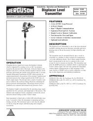
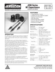
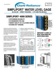
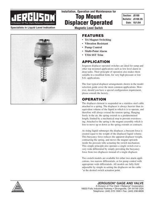
A Division Of The <strong>Clark</strong>-<strong>Reliance</strong> CorporationSpecialists in Liquid <strong>Level</strong> Indication®Installation, Operation and Maintenance for<strong>Top</strong> <strong>Mount</strong><strong>Displacer</strong> <strong>Operated</strong>Magnetic <strong>Level</strong> <strong>Switch</strong>FEATURES• Tri-Magnet <strong>Switch</strong>ing• Vibration Resistant• Pump Control• Multi-Point Alarm• T316 SST TrimSection: JS100Bulletin: JS100.05Date: 10/1/04APPLICATIONJerguson displacer operated switches are ideal for sump andother top mounted applications such as low level alarm indeep tanks. Their principle of operation also makes themsuitable in a modified form, for very high pressure or lowS.G. applications.The four typical displacer arrangements shown in the modelselection guide cover the most common applications. However,should you have a special configuration requirement,please consult the factory.OPERATIONThe displacer element is suspended on a stainless steel cableattached to a spring. The displacer is always heavier than itsequivalent volume of the liquid in which it is to operate, andtherefore will always extend the tension spring. Hangingfreely in the air, the spring extends to a predeterminedlength, limited by a mechanical stop to prevent overstressing.Attached to the spring is the magnet assembly which isfree to move up or down as the spring extends or contracts.As rising liquid submerges the displacer, a buoyant force iscreated equal to the weight of the displaced liquid volume.This buoyancy force reduces the apparent displacer weight,contracting the spring, and moves the magnet upwardsinside the pressure tube actuating the switch mechanism.This simple principle also operates a single switch over avery wide differential by simply providing the buoyancyforce from two displacers instead of a single displacer.Two switch models are available for either two alarm applications,two narrow differentials, or for pump control withappropriate wide differentials. All models are fully fieldadjustable by simple re-setting the displacers on the cable"at the desired switch actuation point.JERGUSON ® GAGE AND VALVEA Division of The <strong>Clark</strong> • <strong>Reliance</strong> ® Corporation16633 Foltz Industrial Parkway • Strongsville, OH 44149 USATelephone: (440) 572-1500 • Fax: (440) 238-8828
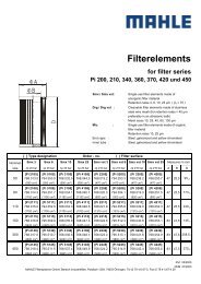
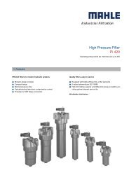
ORDERING INFORMATIONINTERNAL MOUNT DISPLACER TYPESCODE Function-Differential <strong>Displacer</strong> SPDT* DPDT* ToleranceJDC1D Single <strong>Switch</strong>-Narrow 316-SST .50 - 1.2 .50 - 1.2 N/AJDC4D Single <strong>Switch</strong>-Narrow Porcelain .50 - 1.2 .50 - 1.2 N/AJDC2D Single <strong>Switch</strong>-Wide 316-SST .50 - 1.2 .50 - 1.2 ±10%JDC5D Single <strong>Switch</strong>-Wide Porcelain .50 - 1.2 .50 - 1.2 ±10%JDC3D Duel <strong>Switch</strong>-Wide 316-SST .60 - 1.2 .80 - 1.2 ±5%JDC6D Duel <strong>Switch</strong>-Wide Porcelain .60 - 1.2 .80 - 1.2 ±5%JDC8D Duel <strong>Switch</strong>-Narrow 316-SST .60 - 1.2 .80 - 1.2 ±10%JDC9D Duel <strong>Switch</strong>-Narrow Porcelain .60 - 1.2 .80 - 1.2 ±10%ENCLOSURE TYPES*Each unit is calibrated to operate at thespecified S.G. within listed ranges.Duty Material Material Material of Material of Maximumof cover of base pressure screwed number oftube union switchesSA7 Explosion- Aluminum Alloy2 x fourproof 316 To match contactS17 Cast IronStainless chamber orSA4 Weather- Drawn Aluminum Steel material 2 x eightproof Steel Alloy contactINTERNATIONAL APPROVALSU Underwriters Laboratories CI. I, Div. 1, Grp. C & DC Canadian Standards Association CI. I, Div. 1, Grp. C & DB BASEEFA/CENELEC E Exd IIC T6; BS5501: Pts 1 & 5H Underwriters Laboratories CI. I, Div. 1, Grp. B, C & DN Weatherproof to NEMA 4X/IP66 U.L. CSA EANSWNUMBER OF SWITCH MECHANISMSRefer to <strong>Displacer</strong> Function for No. of <strong>Switch</strong>esSWITCH MECHANISM TYPESTemp AC max. values DC max. valuesWetsideRes. Ind.°F VA Volts Amps Watts Volts Amps AmpsD4 4 Contact 750 2000 440 5 50 250 5 0.5X4 480 2000 440 10 50 250 10 0.5H4 Link for SPDT 480 2000 440 10 50 250 10 0.5P4 Two independent single polesingle throw contact sets 750 6 250 0.25 3.6 250 0.25 0.1D8 8 Contact 750 2000 440 5 50 250 5 0.5X8 480 2000 440 10 50 250 10 0.5H8 480 2000 440 10 50 250 10 0.5P8 750 6 250 0.25 3.6 250 0.25 0.1Link for DPDTFour independent single polesingle throw contact setsOTYPICAL MODELJDC 2D SA4 N 1 X4 / 60<strong>Displacer</strong>EnclosureApprovalNo. of <strong>Switch</strong>es<strong>Switch</strong> MechanismOMOUNTING CONNECTION –MATERIAL OF CONSTRUCTIONMODEL JDC - CARBON STEEL MODEL JDS - 316 SSTDISPLACER FUNCTIONSSingle switch narrowdifferential: 1D, 4D.Specify for alarm duty, bi levelor lo level.<strong>Switch</strong>ing level can be changedby simply moving the displacerup or down the cable.SST CABLE 10 FT. LONGSingle switch widedifferential: 2D, 5D.The two displacer elementsare positioned at any point onthe cable to correspond to theswitching levels required. Whenthe liquid level drops to the lowerdisplacer, a switch is actuatedand starts (or stops) a pump,when the liquid rises to theupper displacer,the switch isagain actuatedto stop (or start)the pump.Two switch 2 narrowdifferentials: 8D, 9D.The displacers are positionedto form two elements ofsimilar lengths, such that twoalarm points may be given.This arrangement is typicalof sump application.Two switch 2 widedifferentials: 3D, 6D.A pump is controlled betweenthe middle and the lowerdisplacers positioned on thecable at the required levels.Should the level rise to theupper displacer, this actuatesthe upper alarmswitch which remainsactuated until the leveldrops to the middle displacer.Alternatively the upperswitch could control asecond pump.NOTE: All models supplied with 10 ft. long SST Cable as Standard.MOUNTING CONNECTIONCODE SIZE CARBON STEEL RATING SST RATING60 3" 150# R.F. ANSI 285 PSIG @ 100°F 275 PSIG @ 100°F61 3" 300# R.F. ANSI 740 PSIG @ 100°F 720 PSIG @ 100°F62 3" 600# R.F. ANSI 1480 PSIG @ 100°F 1400 PSIG @ 100°F65 4" 150# R.F. ANSI 285 PSIG @ 100°F 275 PSIG @ 100°F66 4" 300# R.F. ANSI 740 PSIG @ 100°F 720 PSIG @ 100°F67 4" 600# R.F. ANSI 1480 PSIG @ 100°F 1400 PSIG @ 100°F69 6" 150# R.F. ANSI 285 PSIG @ 100°F 275 PSIG @ 100°F80 2 1/2" NPT 1000 PSIG @ 100°F 1000 PSIG @ 100°F90 3" NPT 1000 PSIG @ 100°F 1000 PSIG @ 100°F
DIMENSIONAL AND OPERATING LEVEL DATAID SST: A = 7 1/2 D = 2 1/2 2D SST: A = 7 1/2 D = 2 1/2 8D SST: A = 7 1/2 D = 2 1/2 3D SST: A = 7 12 B = 4 D = 2 1/2S.G. 0.50 0.60 0.80 1.00 S.G. 0.50 0.60 0.80 1.00 S.G. 0.80 0.90 1.00 1.10 S.G. 0.80 0.90 1.00 1.10E min. 3 1/2" 3" 2 1/2" 2" E min. 7 1/4" 6 1/4" 5 1/4" 4 5/8" E min. 2 1/2" 2 1/4" 2" 1 7/8" E min. 5" 4 3/4" 4 1/2" 4 1/4"4D Porcelain: A = 7 3/4 D = 2 9/16 5D Porcelain: A = 7 3/4 D = 2 9/16 9D Porcelain: A = 9 1/2 D = 2 9/16 6D Porcelain: A = 7 3/4 B = 3 7/8 D = 2 9/16S.G. 0.50 0.60 0.80 1.00 S.G. 0.50 0.60 0.80 1.00 S.G. 0.80 0.90 1.00 1.10 S.G. 0.80 0.90 1.00 1.10E min. 3 5/8" 3" 2 3/8" 2" E min. 7 1/4" 6 5/8" 5 1/2" 5" E min. 3 1/2" 3 1/4" 3" 2 3/4" E min. 4 7/8" 4 1/2" 4 1/4" 4"E min. = DifferentialENCLOSURE DIMENSIONAL DATAType Duty Height G Conduit Thread Weatherproof RatingSA7, S17 Explosionproof 13 3/4" 1" NPT NEMA 4x & 7SA4 Weatherproof 12" 1" NPT NEMA 4xMATERIALS OF CONSTRUCTIONTechnical Specification Model JDC Model JDSMaterials of Construction Carbon Steel Chamber Stainless Steel ChamberPressure Tube ASTM A312 T316 ASTM A312 T316Pressure Tube Fitting 1018 C.S. T316 LSSTFlange ASTM A105 ASTM A182 F316<strong>Displacer</strong> As specified As specifiedSpring Iconel 625 Iconel 625Trim T316 SST T316 SSTOptions:• Low temperature carbon steel chambers • Controls to meet N.A.C.E. requirements • A comprehensive N.D.T. package5 YEARMECHANICALWARRANTYWARRANTY STATEMENTAll Jerguson ® mechanical level devices are warrantedfree of defects in materials and workmanship for fiveyears from the date of original factory shipment.If returned within the stated warranty period; and uponfactory inspection the cause of the claim is determinedto be covered under the warranty: at Jerguson’s option,the device will be repaired or replaced without cost tothe purchaser (or owner) other than transportation.Jerguson shall not be liable for mis-application, laborclaims, direct or consequential damage or expensearising from the installation or use of the equipment.There are no other warranties expressed or implied.
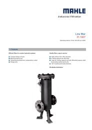
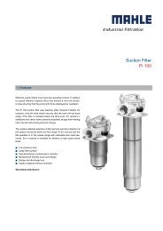
Installation, Operation and Maintenance Instructions • <strong>Top</strong> <strong>Mount</strong> <strong>Displacer</strong> <strong>Operated</strong> Magnetic <strong>Level</strong> <strong>Switch</strong>JERGUSON LEVEL SWITCHESTHE SWITCH MECHANISMPrinciple of OperationThe switch mechanism is based on a unique three-dimensional magnet designwhere the snap action is accomplished by the utilization of magnetic repulsion.The magnet mounted on the float road causes the secondary magnet torotate as it passes up and down. The switch magnet is repelled by the secondaryand snaps to the opposite side. This causes the cradle to pivot, moving thepush rods which operated the switch contacts. The result is positive snapaction interlock switching…no springs…no spring problems.Schematic showing three-magnet systemChoice of <strong>Switch</strong> MechanismsTypeApplicationX4, X8 General purpose – 10 amp mechanisms for general purpose duties up to 480°FD4, D8 High temperature – 750°F mechanisms for high temperature applications up to5 ampsH4, H8 Hermetically sealed – Suitable for low temperature duties, contaminated atmosphereenvironments and intrinsically safe circuits. All moving parts and contactsenclosed in an inert gas filled stainless steel enclosure.P4, P8 Low current – Gold-plated contact switch mechanism for use in intrinsically safeor low power circuits up to 750°F4 Contact Type D4, X4, P4, H42 x S.P.S.T.AA Make on RiseBB Make on FallLink for SPDT/SPCO8 Contact Type D8, X8, P8, H8D.P.D.T.4 x S.P.S.T.AA Make on RiseBB Make on FallLink for DPDT/DPCOPRINCIPLE OF OPERATIONThe displacer element, made of either stainlesssteel or ceramic depending upon the application,is suspended on a stainless steel cable from aspring. The displacer element is always heavierthan its equivalent volume of the liquid in whichit is to operate, and therefore will extend the tensionspring at all times. Hanging freely, thespring will extend to a known length, controlledby a mechanical stop to prevent overstressing.Attached to the spring is the rod and magnetassembly, which is free to move up and downwithin the pressure tube as the spring extends orcontracts, actuating the switch mechanism.As rising liquid submerges the displacer, a buoyancy force is created equal to theweight of the displaced liquid volume. This force reduces the apparent weight of thedisplacer, contracting the spring and moving it upwards inside the pressure tube,actuating the switch mechanism. On a falling liquid level, the displacer element isuncovered and the spring senses an increasing effective weight, extending the spring.The increased effective weight moves the magnet to re-set the switch mechanism.This simple principle can berefined to operate a single switchover a very wide differential byproviding the buoyancy forcefrom two displacer elementsinstead of a single one.Two switch models are availablefor two applications with two narrowdifferentials for pump controlwith appropriate wide differentials.In all cases, because the elementsare suspended on a cable, switchingor control levels may be manyfeet below the mounting flange,and are fully field adjustable tore-setting the displacer elementson the cable.
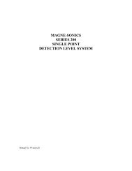
Installation, Operation and Maintenance Instructions • <strong>Top</strong> <strong>Mount</strong> <strong>Displacer</strong> <strong>Operated</strong> Magnetic <strong>Level</strong> <strong>Switch</strong>JERGUSON “FIT & FORGET” PRODUCTS PROVIDE THESOLUTION TO YOUR LIQUID LEVEL CONTROL PROBLEMSMedium PressuresANSI Class 150, 300, 600SG 0.40High PressuresANSI Class 900, 1500, 2500SG 0.40Direct <strong>Mount</strong>ingANSI Class 150, 300, 600SG 0.40You can rely on usThe Jerguson range of liquid level controls is designed foroperation in a wide variety of applicationsJerguson level switches are used for the control of liquidsby companies all over the world.Typical ApplicationsSeparatorsCompressorsKnock-out PotsCondensorsDe-actuatorsStorage TanksService TanksHeader TanksEffluent Sumps & TanksHeat ExchangerLube Oil TanksWater SumpsScrubbersFractioning ColumnsProcess VesselsCondensate TanksDrainpotsAccumulatorsFlash VesselsFuel TanksFeedwater HeatersSurge DrumsShellExxonAmocoFluorHyundaiHitachiBritish PetroleumMobilTexacoIngersoll RandCompairHoneywellBechtelBelliliOntario HydroNissaci-SangyoFoster WheelerSiemensMannesmann-DemagCatalyticTechniTechnipetrolNuovo PignoneDresserJERGUSON ® GAGE AND VALVEA Division of The <strong>Clark</strong> • <strong>Reliance</strong> ® Corporation16633 Foltz Industrial Parkway • Strongsville, OH 44149 USATelephone: (440) 572-1500 • Fax: (440) 238-8828