Measurement Lab. Resistance Temperature Detector (RTD) - FET
Measurement Lab. Resistance Temperature Detector (RTD) - FET
Measurement Lab. Resistance Temperature Detector (RTD) - FET

You also want an ePaper? Increase the reach of your titles
YUMPU automatically turns print PDFs into web optimized ePapers that Google loves.
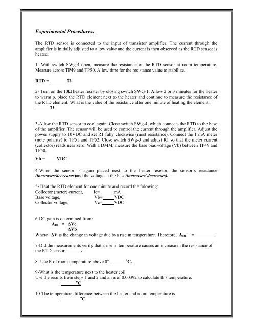
Experimental Procedures:The <strong>RTD</strong> sensor is connected to the input of transistor amplifier. The current through theamplifier is initially adjusted to a low value and the current is then observed as the <strong>RTD</strong> sensor isheated.1- With switch SWg-4 open, measure the resistance of the <strong>RTD</strong> sensor at room temperature.Measure across TP49 and TP50. Allow time for the resistance value to stabilize.<strong>RTD</strong> =Ώ2- Turn on the 10Ώ heater resister by closing switch SWG-1. Allow 2 or 3 minutes for the heaterto warm p. place the <strong>RTD</strong> element next to the heater and continue to measure the resistance ofthe <strong>RTD</strong> element. What is the value of the resistance after one minute of heating the element.Ώ3-Allow the <strong>RTD</strong> sensor to cool again. Close switch SWg-4, which connects the <strong>RTD</strong> to the baseof the amplifier. The sensor will be used to control the current through the amplifier. Adjust thepower supply to 10VDC and set R1 fully clockwise (most resistance). Connect the 1 mA meter(note polarity) to TP51 and TP52. Close switch SWg-3 and adjust R1 so that the meter current(collector) reads near zero. With a DMM, measure the base bias voltage (Vb) between TP49 andTP50.Vb =VDC4-When the sensor is again placed next to the heater resistor, the sensor`s resistance(increases/decreases)and the voltage at the base(increases/ decreases).5- Heat the <strong>RTD</strong> element for one minute and record the folowing:Collector (meter) current, Ic= mABase voltage, Vb= VDCCollector voltage, Vc= VDC6-DC gain is determined from:A DC = ΔVcΔVbWhere ΔV is the change in voltage due to a rise in temperature. Therefore, A DC = .7-Did the measurements verify that a rise in temperature causes an increase in the resistance ofthe <strong>RTD</strong> sensor .8- Use R of room temperature above 0 o o C.9-What is the temperature next to the heater coil.Use the results from steps 1 and 2 and an α of 0.00392 to calculate this temperature.o C10-The temperature difference between the heater and room temperature iso C