EE 421: Communications I Dr. Mohammed Hawa Project: FM ... - FET
EE 421: Communications I Dr. Mohammed Hawa Project: FM ... - FET
EE 421: Communications I Dr. Mohammed Hawa Project: FM ... - FET

You also want an ePaper? Increase the reach of your titles
YUMPU automatically turns print PDFs into web optimized ePapers that Google loves.
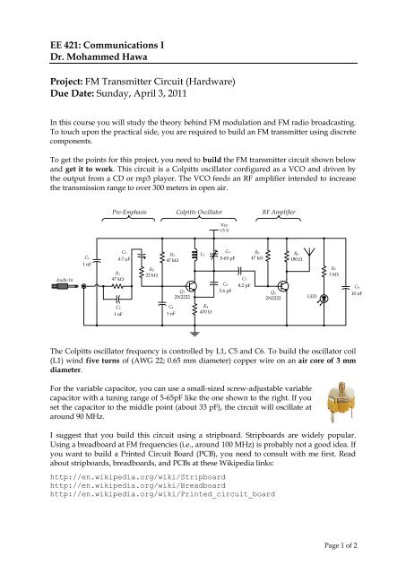
<strong>EE</strong> <strong>421</strong>: <strong>Communications</strong> I<strong>Dr</strong>. <strong>Mohammed</strong> <strong>Hawa</strong><strong>Project</strong>: <strong>FM</strong> Transmitter Circuit (Hardware)Due Date: Sunday, April 3, 2011In this course you will study the theory behind <strong>FM</strong> modulation and <strong>FM</strong> radio broadcasting.To touch upon the practical side, you are required to build an <strong>FM</strong> transmitter using discretecomponents.To get the points for this project, you need to build the <strong>FM</strong> transmitter circuit shown belowand get it to work. This circuit is a Colpitts oscillator configured as a VCO and driven bythe output from a CD or mp3 player. The VCO feeds an RF amplifier intended to increasethe transmission range to over 300 meters in open air.Pre-Emphasis Colpitts Oscillator RF AmplifierVcc+3 VAudio InC 11 nFC 34.7 mFR 147 kWR 222 kWR 347 kWQ 12N2222C 5L 1R 55-65 pF 47 kWC 7C 6 8.2 pF5.6 pFQ 22N2222R 6180 WLEDR 71 kWC 810 nFC 21 nFC 41 nFR 4470 WThe Colpitts oscillator frequency is controlled by L1, C5 and C6. To build the oscillator coil(L1) wind five turns of (AWG 22; 0.65 mm diameter) copper wire on an air core of 3 mmdiameter.For the variable capacitor, you can use a small-sized screw-adjustable variablecapacitor with a tuning range of 5-65pF like the one shown to the right. If youset the capacitor to the middle point (about 33 pF), the circuit will oscillate ataround 90 MHz.I suggest that you build this circuit using a stripboard. Stripboards are widely popular.Using a breadboard at <strong>FM</strong> frequencies (i.e., around 100 MHz) is probably not a good idea. Ifyou want to build a Printed Circuit Board (PCB), you need to consult with me first. Readabout stripboards, breadboards, and PCBs at these Wikipedia links:http://en.wikipedia.org/wiki/Stripboardhttp://en.wikipedia.org/wiki/Breadboardhttp://en.wikipedia.org/wiki/Printed_circuit_boardPage 1 of 2
Antenna:The antenna should be a half or quarter wavelength long(for 100 MHz, this is 150 cm or 75 cm). I suggest you use a 75cm piece of wire or an old extendable <strong>FM</strong> radio antenna(like the one shown here).Battery:I suggest you run this circuit from a 2x1.5 V battery set. I donot recommend using a common 3V DC supply since thoseare not well regulated, and the variations in their voltage might affect your circuit. If youdecide to use a DC power supply, however, I suggest you use a heavily-regulated DCsupply (or add a regulator yourself) to get the best results.Use a CD or mp3 player as the input to your circuit, then use an <strong>FM</strong> radio to listen to yourtransmission. Be prepared to present your work and answer any questions I ask about yourcircuit.Page 2 of 2