

Self-Study Programme 195 The 2.3 ltr V5 Engine - Volkspage
Self-Study Programme 195 The 2.3 ltr V5 Engine - Volkspage
Self-Study Programme 195 The 2.3 ltr V5 Engine - Volkspage
- No tags were found...

You also want an ePaper? Increase the reach of your titles
YUMPU automatically turns print PDFs into web optimized ePapers that Google loves.
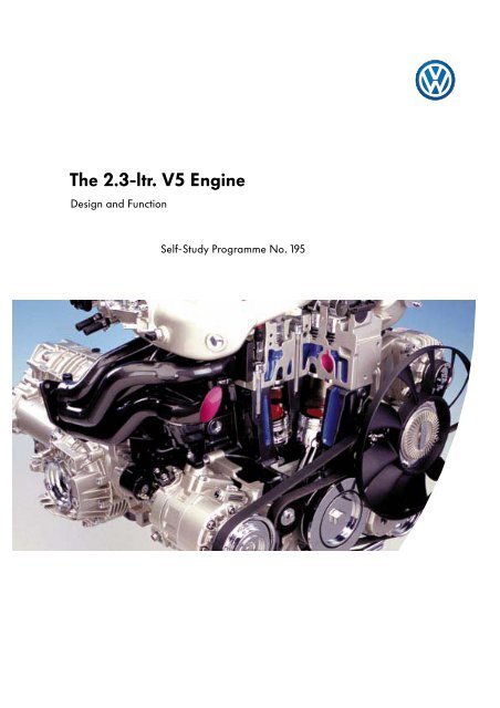
<strong>The</strong> <strong>2.3</strong>-<strong>ltr</strong>. <strong>V5</strong> <strong>Engine</strong>Design and Function<strong>Self</strong>-<strong>Study</strong> <strong>Programme</strong> No. <strong>195</strong>
<strong>The</strong> contents of this SSP at a glanceIntroduction 4<strong>Engine</strong> mechanicals 6Power transmission 11Motronic injection and ignition system 14Function diagram 32Service 34<strong>Self</strong>-diagnosis 363
IntroductionWhy do V-engines exist?Front-wheel drive, in combination with a transverselymounted four-cylinder inline engine, isnow part and parcel of many motor vehicleconcepts. Installing the engine transversely haspromoted the development of more compactvehicles.But the vehicle width is not sufficient toaccommodate inline engines with more than fourcylinders.This is why the V-engine came into being.Al-though V-engines have a very short overalllength, they are rather wide - with a V-angle of60° or 90° - and hence cannot be used insmaller mid-range vehicles.V-engine with an angle of 15°<strong>The</strong> VR engines and the new <strong>V5</strong> enginecombine the advantages of the V-concept withthe advantages of the inline engine.<strong>The</strong>se are:l short overall length thanks to V-angle,l small overall width thanks to theV-angle of 15°,l only one cylinder head is required,<strong>The</strong> <strong>V5</strong> was derived from the VR6 by removingthe 1st cylinder from the latter.<strong>The</strong> resulting, even more compact design makesit possible to use this powerful unit in all vehicleclasses.<strong>195</strong>_0854
Technical specifications<strong>Engine</strong> codeAGZV-angle 15°Displacement 2324 cm 3BoreStroke81.0 mm90.2 mmCompression ratio 10.0 : 1Firing order 1 - 2 - 4 - 5 - 3Mixture preparationand ignitionFuelExhaust gas aftertreatmentBosch Motronic M3.8.395 RON unleaded premiumThree-way catalytic converterwith lambda control<strong>The</strong> <strong>V5</strong> engine conforms to exhaust gas level D3.As the power vs. torque curve shows,the remarkable features of thisengine are its immense low-endtorque and high power output in theupper rpm range.Torque[Nm]Power[kW]Max. torque is 220 Nm at 3600 rpmand max. power output is 110 kW at6000 rpm.TorquePower<strong>195</strong>_084<strong>Engine</strong> speed[rpm]5
<strong>Engine</strong> mechanicalsOffsettingTo give you a better understanding of the designfeatures of the <strong>V5</strong> engine and to clarify severaltechnical concepts, we will begin by looking atthe design features of the inline engine.Inline engineIn the inline engine the piston is located directlyabove the centre of the crankshaft. <strong>The</strong> pistonstroke (h) is therefore twice the crank radius (2xr).TDC and BDC are exactly 180° apart.hCon rod bearing cyl. 1TDCBDCrCentre of crankshaftCentrifugal mass<strong>195</strong>_074<strong>195</strong>_079V-engine with an angle of 90°In conventional V-engines the pistons in bothbanks of cylinders are aligned at 60° or 90° toone another. <strong>The</strong> centre lines of the cylindersnevertheless project through the centre of thecrankshaft. <strong>The</strong> piston stroke is then twice thecrank radius in this case, too. But the largeV-angle also means the engine has a largeoverall width.CylinderaxishrCentre of crankshaft<strong>195</strong>_0756
<strong>V5</strong> engine with an angle of 15°As a result of the V-angle of 15°, the <strong>V5</strong> engine isnot as wide as engines with an angle of 60° or90°. <strong>The</strong> <strong>V5</strong> engine can be mounted bothlongitudinally and transversely because it isshorter than an inline engine.Centre line ofcrankshaftCentre line ofcylinderSeveral difficulties had to be overcome duringthe design process, since the 15° V-angle causesthe cylinders to overlap at the bottom.Centre line ofcrankshaft<strong>195</strong>_109<strong>195</strong>_076To avoid these overlaps, it was necessary to shiftthe cylinders slightly further outwards so as toincrease the clearance between the cylinders.This process is known as “offsetting“. In the <strong>V5</strong>engine the offset of each bank of cylinders is12.5 mm.By offsetting the cylinders, their centrelines nolonger project through the centre of the crankshaft.As a result, the pistons travel i na differentline from TDC to BDC than from BDC to TDC.Allowance has to be made for this differencewhen designing the crankpin throw to ensure thatall cylinders have the same ignition point.Offset of bank 112.5 mmOffset of bank 212.5 mmOffset of bank 2Offset of bank 1TDCBDCCentre lineof cylinderCentre line ofcrankshaft<strong>195</strong>_110<strong>195</strong>_0777
<strong>Engine</strong> mechanicals<strong>The</strong> engine control unitChain tensionerRunning in 6 bearings, the crankshaft drives theintake camshaft by means of an intermediateshaft. <strong>The</strong> two chains are designed as singlechains. Each chain has a tensioner actuated bythe oil circuit.Intermediate shaftChain tensionerCrankshaft<strong>195</strong>_047<strong>Engine</strong> lubrication<strong>The</strong> oil pump is driven by the intermediate shaft.<strong>The</strong> oil cooler and oil filter are located in theengine console. When the oil filter is changed,only the paper filter element needs to bereplaced.Oil cooler<strong>Engine</strong> consoleOil filter elementCaseIntermediateshaftA different oil filter type is used for longitudinallyand transversely mountinged engines(see page 34, Service).<strong>195</strong>_048Oil pump8
Drive for auxiliaries<strong>The</strong> longitudinally and transversely mounted <strong>V5</strong> engines have different drives for auxiliaries.Belt routing of longitudinally mounted <strong>V5</strong> with air-conditioning compressorDeflection pulleyMultiple-ribbed beltAlternatorVisco fanCoolant pumpAir-conditioningcompressorDeflection pulleyTension pulley<strong>195</strong>_046In the longitudinally mounted engine the coolant pump is located on the auxiliary holder.As a result, this engine is slightly shorter than the transversely mounted engine.Auxiliary steering pumpMount forvisco fan ringCoolant pump driveTension pulley<strong>195</strong>_049Auxiliary holder9
<strong>Engine</strong> designBelt routing in the transversely mounted <strong>V5</strong> engine with air-conditioning compressorTension pulleyAlternatorCoolant pumpAir-conditioningcompressorAuxiliary steering pump<strong>195</strong>_120In the transversely mounted engine the coolant pump is integrated in the cylinder crankcase.Plastic pipeCoolant pump<strong>195</strong>_12210
Power transmission<strong>The</strong> flywheelenables the crankshaft to rotate evenly due to itsmass. It also acts as a clutch support. <strong>The</strong> clutchtransmits engine torque to the gearbox.<strong>The</strong> torsional oscillations of the engine in the lowspeed range in particular are transferred to thegearbox in the process.This induces vibrations and consequently“gearbox rattle”.<strong>The</strong> dual-mass-flywheelprevents torsional oscillations of the engine frombeing transmitted to the gearbox. As the namesuggests, the dual-mass flywheel consists of twoflywheel masses, a primary centrifugal mass anda secondary centrifugal mass.<strong>The</strong>y are interconnected by means of aspring/damping system.Primary centrifugal mass<strong>Engine</strong> sideGearbox sideSecondary centrifugal massClutchClutch plateSpring/damper system<strong>195</strong>_024<strong>The</strong> dual-mass-flywheels for mounting the engines in the longitudinal and transverse positionsdiffer from one another, since an intermediate plate is required to locate the gearbox forlongitudinal mounting.<strong>Engine</strong>s with dual-mass flywheels have an engine oscillation system which is tuned differently toengines with conventional flywheels.<strong>The</strong>refore, never replace single-mass flywheels with dual-mass flywheels.11
Power transmission<strong>Engine</strong> and gearbox with conventionalflywheel-clutch layout<strong>Engine</strong>Put simply, it can be said that a conventionalfly-wheel is better at absorbing oscillations whichan engine produces. But the remainingoscillations are transmitted fully to the gearbox,and this manifests itself as vibrations and noise inthe low speed range.Gearbox<strong>195</strong>_025Oscillations produced by the engineOscillations absorbed by the gearbox<strong>195</strong>_027Oscillatory behaviour of the engine and gearboxat idling speed<strong>Engine</strong> and gearbox withdual-mass flywheel<strong>The</strong> dual-mass flywheel allows slightly moreengine oscillation, due to its smaller centrifugalmass. In fact, the spring/damping system and thehigher gearbox moment of inertia prevent theseoscillations from being transmitted to thegearbox. This results not only in a much higherlevel of ride comfort, but also in less wear andhigher fuel efficiency at low engine speeds.<strong>Engine</strong>Gearbox<strong>195</strong>_026Oscillations produced by the engineOscillations absorbed by the gearbox<strong>195</strong>_028Oscillatory behaviour of the engine and gearboxat idling speed12
Test your knowledge1. <strong>The</strong> <strong>V5</strong> engine has a V-angle ofa) 15°,b) 60° orc) 90°.2. Annotate the drawing.What belt pulleys drive what units?e)a)f)b)g)h)c)i)d)3. State the advantages of the dual-mass flywheela) Higher ride comfort,b) Higher engine power,c) Less wear,d) Higher fuel efficiency at low engine speedsReasons:13
Motronic injection and ignition systemOverview of Motronic M3.8.3 systemSensorsG70 Air mass meterG28 <strong>Engine</strong> speed senderG40 Hall senderG39Lambda probeG61Knock sensor IG66Knock sensor IIG62 Coolant temperature senderG72Intake manifold temperature senderJ338 Throttle valve control unit withF60 Idling switchG69 Throttle valvepotentiometerG88 Throttle valve positionerpotentiometerFBrake light switchDiagnosisplug conn.F36Clutch switchF63Brake pedal switchE45 Cruise control system switchE227 Cruise control system buttonAdditional input signalse.g. road speed signalJ220 Motronic control unit14
ActuatorsG6J17Fuel pump withFuel pump relayN30 Injector, cylinder 1N31 Injector, cylinder 2N32 Injector, cylinder 3N33 Injector, cylinder 4N83 Injector, cylinder 5N122 Power end stageN Ignition coilN128 Ignition coil 2N158 Ignition coil 3N163 Ignition coil 4N164 Ignition coil 5N79Heater element(crankcase breather valve)N80 Solenoid valve 1 foractivated charcoal filter systemN156 Twin-path intake manifold change-over valveJ338 Throttle valve control unit withV60 throttle valve positioner<strong>195</strong>_105Additional output signals,e.g. to air-conditioning compressor15
Motronic injection and ignition system<strong>The</strong> air mass meter with reverse flow recognitionTo guarantee optimal mixture composition andlow fuel consumption, the engine managementsystem needs to know exactly how much air theengine intakes.<strong>The</strong> air mass meter supplies this information.Air mass meter<strong>The</strong> opening and closing actions of the valvescause the air mass inside the intake manifold toflow in reverse.<strong>The</strong> hot-film air mass meter with reverse flowrecognition detects reverse flow of the air massand makes allowance for this in the signal itsends to the engine control unit. Thus, the airmass is metered very accurately.Reverse flowIntake manifold<strong>195</strong>_094Design<strong>The</strong> electronic circuit and the sensor element ofthe air mass meter are accommodated in acompact plastic housing.HousingHousing coverLocated at the lower end of the housing is ameter-ing duct into which the sensor elementprojects.<strong>The</strong> metering duct extracts a partial flow from theair stream inside the intake manifold and guidesthis partial flow past the sensor element.<strong>The</strong> sensor element measures the intake andreverse air mass flows in the partial air flow.<strong>The</strong> resulting signal for the air massmeasurement is processed in the electronic circuitand sent to the engine control unit.MeteringductElectric circuitPartial air flowSensor element<strong>195</strong>_09216
Functional principleMounted on the sensor element are twotemperature sensors (T1 + T2) and aheating element.<strong>The</strong> substrate to which the sensors and heatingelement are attached is composed of a glassmembrane. Glass is used because of its poorthermal conductivity. This prevents heat which theheating element radiates from reaching thesensors through the glass membrane. This canresult in measurement errors.Air mass meterwith sensor elementinside the metering ductDesign of sensor element(schematic diagram)Air flowT1HeatingelementT2<strong>195</strong>_041<strong>The</strong> heating element warms up the air above theglass membrane.<strong>The</strong> two sensors register the same airtemperature, since the heat radiates uniformlywithout air flow and the sensors are equidistantfrom the heating element.T1T2<strong>195</strong>_042Induced air mass recognitionIn the intake cycle, an air stream is ducted fromT1 to T2 via the sensor element.<strong>The</strong> air cools sensor T1 down and warms upwhen it passes over the heating element, with theresult that sensor T2 does not cool down to asgreat an extent as T1.<strong>The</strong> temperature of T1 is therefore lower than thatof T2. This temperature difference sends a signalto the electronic circuit that air induction hasoccurred.T1T2<strong>195</strong>_04317
Motronic injection and ignition systemReverse air mass flow recognitionIf the air flows over the sensor element in theopposite direction, T2 will be cooled down to agreater extent than T1. From this the electriccircuit recognises reverse flow of the air mass.It subtracts the reverse air mass flow from theintake air mass and signals the result to theengine control unit.<strong>The</strong> engine control unit therefore obtains anelectrical signal: it indicates the actual inducedair mass and is able to meter the injected fuelquantity more accurately.T1T2<strong>195</strong>_044Signal utilisationElectric circuit<strong>The</strong> signal which the air mass meter sends is usedto calculate all speed- and load-dependentfunctions, e.g. injection time, ignition timing ortank venting.<strong>The</strong> air mass meter is connected to the enginecontrol unit via two signal lines and one earthline and is supplied with power via connection87a in the engine wiring harness.Effects of signal failureIn the event of failure of the air mass meter,the engine management system computes asubstitute value. This emergency function is sowell adapted that the fitter cannot tell from therunning behaviour of the engine whether the airmass meter is defective. This can only be done byreading out the fault memory.Power supplyG70This means that the defect will be detected at thelatest during the exhaust emission test whichtakes place every two years if not during theroutine service checks.J220<strong>195</strong>_11118
<strong>The</strong> twin-path intake manifoldTwin-path intake manifolds are a newdevelopment. <strong>The</strong>ir task is to develop highlow-end torque by means of the long port in theintake manifold and deliver high top-end powerby means of the short port in the intake manifold.In contrast to previous systems, change-over ofthe intake manifold paths in the <strong>V5</strong> engine isperformed by a rotary valve instead ofchange-over valves.<strong>195</strong>_131Air flow when using change-over valve<strong>The</strong> change-over valves are housed in the intakeport. As a result, they change the flowcross-section and the flow behaviour of theintake air inside the port. Turbulence occurs evenif the valves are fully open.Change-over valveTurbulence during valve control<strong>195</strong>_022Advantage of using a rotary valve<strong>The</strong> advantage of using a rotary valve instead ofa valve actuator is it ensures optimal flowbehaviour of the air drawn into the intakemanifold.Rotary valve<strong>The</strong> shape of the rotary valve replicates thecross-section of the intake duct.Air-flow behaviour is not impaired when therotary valve is open.As opposed to the valve actuator, turbulencedoes not occur.Closed rotary valve<strong>195</strong>_108<strong>195</strong>_023An optimal flow characteristic is achieved whenthe rotary valve is open19
Motronic injection and ignition systemOn closer examination it can be seen that the processes taking place inside the twin-path intakemanifold are more complex than at first meet the eye. We will therefore devote this section to explainingthe functional principle of the intake manifold, beginning with its design.DesignIntake manifold upper section withtorque and performance ports<strong>The</strong> intake manifold comprises an intakemanifold upper section together with the torqueports, performance ports and rotary valves, andthe intake manifold lower section.In longitudinally and transversely mountedengines the intake manifold is made ofaluminium or plastic respectively.Plastic is the preferred material for transverselymounted engines. This is because the intakemanifold shatters when it collides with the enginecompartment bulkhead in a crash and preventsthe engine from intruding into the passengercompartment.Intake manifoldlowersection<strong>195</strong>_089Rotary valve<strong>The</strong> intake manifold of the <strong>V5</strong> engine is based onthe ram pipe charge principle.Was does this mean?<strong>The</strong> key components of the twin-path intakemanifold are the torque ports and theperformance ports. As their name alreadysuggests, the ports are designed to collectsomething.Indeed, they collect air and produce what isknown as the “self-charging effect“.Torque port<strong>195</strong>_021Output manifoldThis effect arises from the propagation ofpressure waves or oscillations inside the intakemanifold. <strong>The</strong> name “ram pipe charging” isderived from this.<strong>195</strong>_020Intake valveCombustion chamberRotary valve20
ActuationChange-over is speed- and load-dependent.<strong>The</strong> engine control unit activates the solenoidvalve for changing over the ports in the intakemanifold.This valve admits a partial pressure into thevacuum box. <strong>The</strong> vacuum box in turn actuatesthe rotary valve and ensures smooth changeoverseven at high revs. <strong>The</strong> non-return valveprevents the vacuum box from being vented ifpressure fluctuations occur inside the intakemanifold.Position of the twin-path intake manifoldChange-over takes place:up to approx. 900 rpmIdling/performance position = short intake manifoldas of approx. 900 rpmTorque position = long intake manifoldabove approx. 4300 rpmPerformance position = short intake manifoldRotary valveIntake manifoldtoperformance portfromtorque portVacuum boxto intake valveSignal from engine control unitPort change-over valveN156Vacuum boxNonreturn valve<strong>195</strong>_106to fuel pressure regulator21
Motronic injection and ignition systemFunctional principleAfter combustion has taken place, there is apressure differential between the cylinder andintake manifold.When the intake valve opens, an intake waveforms inside the intake manifold and propagatesfrom the inlet port towards the torque port at thespeed of sound.Torque portIntake valveOutput manifoldRotary valve<strong>195</strong>_011<strong>The</strong> open end of the pipe in the torque port hasthe same effect on the intake wave as a solidwall has on a ball. <strong>The</strong> wave is reflected andpropagates back to the inlet port in the form of apressure wave.Reflection pointof torque port<strong>195</strong>_012At an optimal intake manifold length, the max.pressure reaches the inlet port shortly before itcloses.<strong>The</strong> pressure wave enables more air to beadmitted into the cylinder, and improves theamount of fuel-air mixture in the cylinder.This is what’s called the self-charging effect.Inlet port isstill open.<strong>195</strong>_013As engine speed increases, the pressure wavehas less time to reach the inlet port. Because thepressure wave is only able to propagate at thespeed of sound, it reaches the inlet port too late.It is already closed.<strong>Self</strong>-charging does not take place.This problem can be solved by shortening theintake manifold.Inlet port isalready closed<strong>195</strong>_01422
In the <strong>V5</strong> engine, the rotary valve turns to theperformance position at an engine speed of4300 rpm. This opens up the path to theperformance port. <strong>The</strong> performance port isdesigned so that the intake and pressure wavesfollow a shorter path to the inlet port.<strong>The</strong> performance port is filled with air when theinlet ports are closed.Performance portis filled.Rotary valve<strong>195</strong>_015When the inlet port opens, an intake wavepropagates uniformly inside the intake manifold.<strong>The</strong> intake wave reaches the pipe end in theperformance port before it does in the torqueport. <strong>The</strong>re it is reflected and returns to the inletport.<strong>195</strong>_016Reflection point of performance portReflection pointof torque portUnlike the pressure wave which propagates backfrom the torque port, the intake wave arrivesbefore the inlet port closes. It therefore has aself-charging effect.<strong>195</strong>_017<strong>The</strong> wave arriving too late from the torque port isreflected by the closed injectors and fills theperformance port.<strong>195</strong>_01923
Motronic injection and ignition systemCruise controlCruise control enables the driver to set aconstant road speed of 45 kph and above. Onceactivated, cruise control maintains the set speedregardless of topography without the driverhaving to press the accelerator pedal.In the previous system the throttle valve wasopened electro-pneumatically depending on theset road speed.<strong>The</strong> signal which the cruise control switch generates is transmitted to the engine control unit,which in turn activates the throttle valve control unit. A control unit for cruise control is nolonger needed.<strong>The</strong> throttle valve positioner opens the throttle valve depending on the road speed setting.Cruise control switchOn and Off signals<strong>Engine</strong> control unitSignals to the engine control unit<strong>Engine</strong> speed signalAir mass signalRoad speedBrake operatedClutch operatedFeedback signalof throttle valve positionServo motoractuationThrottle valve control unit<strong>195</strong>_093Cruise control only operates at a road speed of 45 kph or above.24
<strong>The</strong> throttle valve control unitVolkswagen has been fitting the throttle valvecontrol unit to its engines since early 1995. After itis activated by the engine control unit, thethrottle valve control unit regulates idling speed.You will find further information on this in SSP173.G88<strong>The</strong> component parts are:l Idling switch F60,l Throttle valve potentiometer G69,l Throttle valve positioner potentiometer G88,l Throttle valve positioner V60.V60F60G69<strong>195</strong>_054<strong>The</strong> throttle valve control unit also actuates thethrottle valve while the cruise control is switchedon.Apart from minor differences, the new throttlevalve control unit has the same design as the oldone.<strong>The</strong> main difference is that the gearwheelsegment is larger. This enables the servo motor tooperate the throttle valve across the fulladjustment range.Gearwheel segment without Gearwheel segment withcruise controlcruise control<strong>195</strong>_055 <strong>195</strong>_05625
Motronic injection and ignition system<strong>195</strong>_057Idling switch F60Signal utilisationWhen the idling switch is closed, the enginemanagement system knows that the engine isidling.Electric circuit<strong>195</strong>_061J220Effects of signal failureIn the event of signal failure, the values of theengine management potentiometer are used todetect when the engine is idling.G40<strong>195</strong>_073J338Sensor earth<strong>The</strong> idling switch utilises the sensor earth of theengine control unit.<strong>195</strong>_060Throttle valve positioner V60<strong>The</strong> throttle valve positioner is an electric motorand has the capability to actuate the throttlevalve over the full throttle valve operating range.Effects of failureTo control idling, the emergency running springdraws the throttle valve into the emergencyrunning position.<strong>The</strong> cruise control fails.Electric circuitG40J338J220<strong>195</strong>_064<strong>195</strong>_070V60 is activated by the engine control unit.26
Throttle valve potentiometer G69Signal utilisation<strong>195</strong>_058This potentiometer enables the engine controlunit to recognise the position of the throttle valve.<strong>195</strong>_062Electric circuitEffect of signal failureJ220If the engine control unit does not receive asignal from this potentiometer, it will compute asubstitute value based on engine speed and thesignal which the air mass meter sends.G40<strong>195</strong>_072J338Sensor earthG69 utilises the sensor earth of the enginecontrol unit. <strong>The</strong> voltage supply is identical tothat of G88.Throttle valve positionerpotentiometer G88<strong>195</strong>_059Signal utilisationThis potentiometer signals the position of thethrottle valve drive to the engine control unit.<strong>195</strong>_063Electric circuitEffect of signal failureJ220If this signal is not received, the idling controlgoes into an emergency mode. A higher idlingspeed indicates this.<strong>The</strong> cruise control fails.G40<strong>195</strong>_071J338Sensor earth27
Motronic injection and ignition system<strong>The</strong> quick-start sender wheelis secured to the camshaft. <strong>The</strong> signal it sendsenables the engine control unit to recognisemore quickly the position of the camshaft inrelation to the crankshaft and, in conjunctionwith the signal which the engine speed sendergenerates, to start the engine more quickly.In previous systems the first combustion cyclewas initiated after a crank angle of approx.600-900°. <strong>The</strong> quick-start sender wheel enablesthe engine control unit to recognise the positionof the crank-shaft in relation to the camshaftafter a crank angle of only 400-480°.As a result, the first combustion cycle can beinitiated sooner and the engine starts morequickly.<strong>The</strong> quick-start sender wheel consists of atwin-track sender wheel and a Hall sensor.<strong>The</strong> sender wheel is designed with two trackslocated side by side. Where one track has a gap,the other track has a tooth.Twin-track sender wheelTrack 1Track 2<strong>The</strong> Hall sensor comprises two Hall elementslocated side by side.Each Hall element scans a single track. Thisdevice is known as a differential Hall sensorbecause the engine management systemcompares the signals of the two elements.ToothGapHallelementtrack 1 <strong>195</strong>_031Hall elementtrack 2Hall sensor28
Function<strong>The</strong> sender wheel is designed so that the two Hallelements never generate the same signal. WhenHall element 1 is facing a gap, Hall element 2 isalways facing a tooth.Hall element 1 therefore always generates adifferent signal to Hall element 2.<strong>The</strong> control unit compares the two signals and isthus is able to recognise the cylinder at which thecamshaft is located.Using the signal which the engine speed senderG28 generates, the injection cycle can beinitiated after a crank angle of approx. 440°.Track 1Track 2Hall element track 2recognises toothSignal 2 =1Hall element track 1recognises gapSignal 1 =0<strong>195</strong>_032Track 1Track 2Hall element track 2recognises gapSignal 2 =0Hall element track 1recognises toothSignal 1 =1<strong>195</strong>_033Electric circuit<strong>The</strong> Hall sender G40 is connected to sensorearth of the engine control unit. If the Hallsender fails, the engine cannot be restarted.J220J338G40<strong>195</strong>_06929
Motronic injection and ignition system<strong>The</strong> ignition system<strong>The</strong> <strong>V5</strong> engine is equipped with a static high voltage distributor.Due to the uneven number of cylinders, the <strong>V5</strong> utilises a power end stage with asingle ignition coil for each cylinder. <strong>The</strong> ignition coils are grouped together in a single module.Motronic engine control unitPower end stage N122Ignition coils N, N128, N158, N163, N164<strong>195</strong>_036Advantages:l No wearl High reliability30
Power end stage N122Each of the five ignition output stages “pumps” ahigh amperage into the ignition coils to ensurethat there is enough power to produce theignition spark.<strong>195</strong>_090Ignition coils N, N128, N158, N163, N164Due to the uneven number of cylinders, it wasnot possible to use twin ignition coils for theignition system as in the case of the VR6 engine.<strong>195</strong>_097Electric circuit<strong>The</strong> power end stage, together with the ignitioncoils and the engine control unit, are suppliedwith power via the fuel pump relay J17. Eachcylinder has its own ignition output stage andtherefore also has an output wire from theengine control unit.SNN128 N158 N163 N164N122J220<strong>195</strong>_11631
Function diagram3015X313015X31J17SSSSSNN128 N158 N163 N164G6G39N80G70N83N33N32N31N30N122J220G88F60G62G72G40J338V60G69G28G66G61ComponentsF60 Idling switchG6 Fuel pumpG28 <strong>Engine</strong> speed senderG39 Lambda probeG40 Hall senderG61 Knock sensor IG62 Coolant temperature senderG66 Knock sensor IIG69 Throttle valve potentiometerG70 Air mass meterG72 Intake manifold temperature senderG88 Throttle valve positioner potentiometerJ17 Fuel pump relayJ220 Motronic control unitJ338 Throttle valve control unitN30 Injector, cylinder 1N31 Injector, cylinder 2N32 Injector, cylinder 3N33 Injector, cylinder 4N80 Solenoid valve 1 foractivated charcoal filter systemN83 Injector, cylinder 5N Ignition coil 1N122 Power end stageN128 Ignition coil 2N158 Ignition coil 3N163 Ignition coil 4N164 Ignition coil 5V60 Throttle valve positioner<strong>195</strong>_10332
3015X313015X31SSSN79N156F36F47FE45E227J220A B C D E F G HI J KComponentsE45 Cruise control system switchE227 Cruise control system button (set)F Brake light switchF36 Clutch switchF47 Brake pedal switch for cruise controlG70 Air mass meterJ220 Motronic control unitN79 Heater element(crankcase breather)N156 Intake manifold change-over valveABCDEFGHIJK<strong>195</strong>_104Road speed signalFuel consumption indicator signal<strong>Engine</strong> speed signalAir conditioning on standbyThrottle valve position signalDiagnostics/immobiliser data wireAir-conditioning compressorAutomatic gearbox signalABS/EDL data lineABS/EDL data lineAutomatic gearbox signal33
ServiceLongitudinal and transversemountingPlease note that the add-on parts of the <strong>V5</strong>engine for longitudinal and transverse mountingare very different.<strong>The</strong> parts highlighted in blue indicate where the<strong>V5</strong> engine intended for longitudinal mountingshown below differs from the engine intendedfor transverse mounting.Heat shieldVisco fanPosition of secondary air valveDipstickAlternatorCombinedholderExhaustmanifoldCoolant pump<strong>Engine</strong> consoleAir-conditioningcompressorOil filter<strong>195</strong>_045Auxiliary steeringpumpOil sump34
Special toolsFor the <strong>V5</strong> engine, additional holes must be drilled in special tools <strong>Engine</strong> Holder 3269 andCounter-holder 3406.For <strong>Engine</strong> Holder 3269, mark three drill-holesfrom the centre outwards. Please note that holesmay only be drilled for the engine which hascode AGZ, i.e. the longitudinally mountedengine.<strong>195</strong>_099For Counter-holder 3406, position the drill-holesin parallel with the existing drill-hole.<strong>The</strong>n seal the surface of the special tool withcorrosion inhibitor.<strong>195</strong>_10035
<strong>Self</strong>-diagnosisYou can select the following functions in the selfdiagnosis:01 Interrogate control unit version02Interrogate fault memory03 Actuator diagnosis04 Basic adjustment05 Erase fault memory06 End of output07 Encode control unit08 Read measured value block10 AdaptationBasic adjustment must be performed after completing the following work:- <strong>Engine</strong> control unit,- Throttle valve control unit,- replace engine or- disconnect battery terminalsFunction 02 Interrogate fault memory<strong>The</strong> self-diagnosis stores faults in the components highlighted below in the fault memory.<strong>The</strong>se faults can be read using fault reader V.A.G. 1551 or V.A.G. 1552.G70J17G28N30, N31, N32, N33, N83G40G39G61G66G62G72J338 withF60G69G88FF36F63N80N156J338 withV60E45E227J220<strong>195</strong>_11736
Test your knowledge1. What is the special feature of the new hot-film air mass meter?2. Annotate the following drawing.a)b)c)f)g)h)d)i)e)j)k)3. Why does the engine start more quickly with a quick-start sender wheel?4. What is a performance port and what purpose does it serve?37
38Notes
Solutions:Page 131. a)2. a) Deflection pulley, b) Air-conditioning compressor, c) Deflection pulley, d) Crankshaft, e) Alternator, f) Visco van,g) Coolant lpump, h) Tension pulley, i) Auxiliary steering pump3. a), c), d)4. Fewer oscillations are transmitted from the engine to the gearbox.Page 371. <strong>The</strong> air mass meter has reverse flow recognition.2. a) Rotary valve, b) to output manifold, c) Vacuum box, d) Signal from engine control unit, e) Vacuum box,f) Intake manifold , g) from torque port, h) to intake valve, i) Register intake manifold change-over valve, j) Nonreturn valve,k) to fuel-pressure regulator3. Thanks to the configuration of the gear teeth and gaps on the two-track sender wheel and the Hall sensor with twoHall elements, the engine control unit receives a signal which enables it to determine the position of the camshaft inrelation to the crankshaft more quickly.4. <strong>The</strong> performance port is a component part of the twin-path intake manifold.It serves to improve volumetric efficiency in the upper speed range and thus to increase power output.39
Service. <strong>195</strong>For internal use only © VOLKSWAGEN AG, WolfsburgAll rights reserved. Subject to change.740.2810.13.20 Technical status: 12/97` This paper was made from chlorinefreebleached cellulose.


