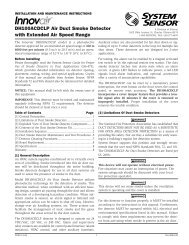
DH100LP Air Duct Smoke Detector with Extended Air Speed Range
DH100LP Air Duct Smoke Detector with Extended Air Speed Range
DH100LP Air Duct Smoke Detector with Extended Air Speed Range

You also want an ePaper? Increase the reach of your titles
YUMPU automatically turns print PDFs into web optimized ePapers that Google loves.
WARNINGIn no case should more than 2 air inlet holes be cut off thetube. There must be a minimum of 10 holes in the tubeexposed to the air stream.[5.4.2] Installation For <strong>Duct</strong>s More Than 8 Feet WideNOTE: To install inlet tubes in ducts more than 8 feet wide,work must be performed inside the air duct.Sampling of air in ducts wider than 8 feet is accomplishedby using the ST-10 inlet sampling tube. If thetube is shorter than the width of the air duct, installthe end plug into the inlet tube as shown in Figure4 and support the end opposite the duct smokedetector.Install the inlet tube as follows:1. Drill a 3 ⁄4-inch hole in the duct opposite the hole alreadydrilled for the inlet tube. Drill the hole 1″ to 2″ below theinlet hole on the opposite side of the duct to allow formoisture drainage away from the detector.2. Slide the inlet tube <strong>with</strong> the flange into the housing bushingthat meets the air flow first. Position the tube so thatthe arrows point into the air flow. Secure the tube flangeto the housing bushing <strong>with</strong> two #6 self-tapping screws.3. From inside the duct, couple the other sections of theinlet tube to the section already installed using the1⁄2-inch conduit fittings supplied. Make sure that theholes on both of the air inlet tubes are lined up and facinginto the air flow.4. Trim the end of the tube protruding through the duct sothat 1″ to 2″ of the tube extend outside the duct. Plugthis end <strong>with</strong> the end plug and tape closed any holes inthe protruding section of the tube. Be sure to seal theduct when the tube protrudes.NOTE: An alternate method to using the ST-10 is to usetwo ST-5 inlet tubes. Remove the flange from oneof the tubes and install as described above. Afterthe installation, use electrical tape to close offsome of the sampling holes so that there are a totalof 10 to 12 holes spaced as evenly as possibleacross the width of the duct.NOTE: <strong>Air</strong> currents inside the duct may cause excessivevibration, especially when the longer sampling tubes areused. In these cases a 3 inch floor flange (available at mostplumbing supply stores) may be used to fasten the samplingtube to the other side of the duct. When using theflange/connector mounting technique, drill a 1 to 1 1 ⁄4 inchhole where the flange will be used.[5.4.3] Modifications of Inlet Sampling TubesThere may be applications where duct widths are not whatis specified for the installation. In such cases, it is permissibleto modify an inlet sampling tube that is longer thannecessary to span the duct width.Use a 0.193-inch diameter (#10) drill and add the appropriatenumber of holes so that the total number of holesexposed to the air flow in the duct is 10 to 12. Space theadditional holes as evenly as possible over the length of thetube.NOTE: This procedure should only be used as a temporaryfix. It is not intended as a permanent substitute forordering the correct length tubes.[5.5] Install The FiltersTo install the sampling tube filters, simply push the filtersinto the sampling and exhaust tube holes as shown inFigure 6. If a metal sampling tube is used, install the filterover the sampling tube.Figure 6. Sampling tube filter installation:WARNINGFilters require periodic cleaning or replacement, dependingon the amount of dust and dirt accumulated. Visuallyinspect the filters at least quarterly; inspect them moreoften if the dust accumulation warrants it. See Section [6]for more information. Replacement filters can be orderedfrom System Sensor, 3825 Ohio Ave., St. Charles, IL 60174.(Exhaust tube/intake tube filter P/N F36-09-11)[5.6] Field WiringWiring Installation GuidelinesAll wiring must be installed in compliance <strong>with</strong> theNational Electrical Code and the local codes having jurisdiction.Proper wire gauges should be used. The conductorsused to connect smoke detectors to control panels andaccessory devices should be color-coded to prevent wiringmistakes. Improper connections can prevent a system fromresponding properly in the event of a fire.D200-15-00 4 I56-0083-00