DH100LP Air Duct Smoke Detector with Extended Air Speed Range
DH100LP Air Duct Smoke Detector with Extended Air Speed Range
DH100LP Air Duct Smoke Detector with Extended Air Speed Range

You also want an ePaper? Increase the reach of your titles
YUMPU automatically turns print PDFs into web optimized ePapers that Google loves.
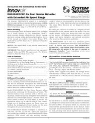
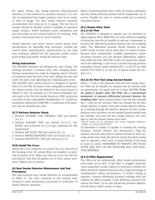
For signal wiring, (the wiring between interconnecteddetectors or from detectors to auxiliary devices), it is usuallyrecommended that single conductor wire be no smallerthan 18 gauge. The duct smoke detector terminalsaccommodate wire sizes up to 12 gauge. The last foot ofconduit should be flexible conduit (available in electricalsupply houses), which facilitates easier installation andputs less strain on the conduit holes in the housing. Solidconduit connections may be used if desired.<strong>Smoke</strong> detectors and alarm system control panels havespecifications for allowable loop resistance. Consult thecontrol panel manufacturer’s specifications for the totalloop resistance allowed for the particular model controlpanel being used before wiring the detector loop.Wiring InstructionsThe <strong>DH100LP</strong> detectors are designed for easy wiring. Thehousing provides a terminal strip <strong>with</strong> clamping plates.Wiring connections are made by stripping about 3/8-inchof insulation from the end of the wire, sliding the bare endunder the plate, and tightening the clamping plate screw.The <strong>DH100LP</strong> duct smoke detector is designed to operate<strong>with</strong> 12 or 24 VDC UL listed 2-wire compatible control panels.Alarm current must be limited by the control panel to100mA or less. An example of a UL listed compatible controlpanel is the Fire-Lite model Sensiscan 1000 using zonecard ANC-2 and compatibility identification “A”. Install perinstallation instruction S1000/801. A maximum of 20 detectorsmay be installed per zone.[5.7] Perform <strong>Detector</strong> Check1. Perform STANDBY AND TROUBLE TEST per Section[6.2.1].2. Perform MAGNET TEST per Section [6.2.2.1]. TheRTS451 test of Section [6.2.2.2] may substitute for thisrequirement.3. Perform AIR FLOW TEST per Section [6.1.1].4. Perform SMOKE RESPONSE TEST per Section [6.1.2].5. Perform SENSITIVITY TEST per Section [6.2.3].[5.8] Install The CoverInstall the cover using the six screws that are captured inthe housing cover. Be certain filters are installed as specifiedin Section [5.5]. Make sure that the cover fits into thebase groove and that all gaskets are in their proper positions.Tighten the six screws.[6] <strong>Duct</strong> <strong>Smoke</strong> <strong>Detector</strong> Maintenance And TestProceduresTest and maintain duct smoke detectors as recommendedin NFPA 72. The tests contained in this manual weredevised to assist maintenance personnel in verification ofproper detector operation.Before conducting these tests, notify the proper authoritiesthat the smoke detection system will be temporarily out ofservice. Disable the zone or system under test to preventunwanted alarms.[6.1] <strong>Smoke</strong> Entry Tests[6.1.1] <strong>Air</strong> FlowThe <strong>DH100LP</strong> is designed to operate over an extended airspeed range of 100 to 4000 FPM. To verify sufficient samplingof ducted air, turn the air handler on and use a manometer tomeasure the differential pressure between the two samplingtubes. The differential pressure should measure at least0.0015 inches of water and no more than 1.2 inches of water.Because most commercially available manometers cannotaccurately measure very low pressure differentials, applications<strong>with</strong> less than 500 FPM of duct air speed may requireone of the following: 1) the use of a current-sourcing pressuretransmitter (Dwyer model numbers 607-1 or 607-01) see fieldbulletin Z75-79-00 or; 2) the use of aerosol smoke per section6.1.2.[6.1.2] <strong>Air</strong> Flow Test using Aerosol <strong>Smoke</strong>Drill a 1 ⁄4″ hole 3 feet upstream from the duct smoke detector.With the air handler on, measure the air velocity <strong>with</strong>an anemometer. <strong>Air</strong> speed must be at least 100 FPM. If theair speed is greater than 500 FPM, use a conventionalmanometer to measure differential pressure between thesampling tubes. Spray aerosol smoke* into the duct throughthe 1 ⁄4″ hole for five seconds. Wait two minutes for the ductsmoke detector to alarm. If the duct smoke detector alarms,air is flowing through the detector. Remove the duct smokedetector cover and blow out the residual aerosol smoke fromthe chamber and reset the duct smoke detector. Use ducttape to seal the aerosol smoke entry hole.*Aerosol smoke can be purchased from Home Safeguard Industries,Malibu, CA. Phone: 310/457-5813.To determine if smoke is capable of entering the sensingchamber, visually identify any obstructions. Plug theexhaust and inlet tube holes to prevent ducted air from carryingsmoke away from the detector head, then blow smokesuch as cigarette, cotton wick, or punk directly at the headto cause an alarm. REMEMBER TO REMOVE THE PLUGSAFTER THIS TEST, OR THE DETECTOR WILL NOT FUNC-TION PROPERLY.[6.1.3] Filter ReplacementThe filters do not substantially affect smoke performanceeven when up to 90% of the filter is clogged. Quarterlyvisual inspection usually suffices to determine whether thefilters should be replaced because only a high percentage ofcontamination affects performance. If further testing isrequired, compare differential pressure readings <strong>with</strong> and<strong>with</strong>out the filters installed. If the difference exceeds 10%replace the filters. In no case should the pressure differentialfall below 0.0015 inches of water.D200-15-00 5 I56-0083-00