Protocols and Architecture Protocol Architecture. ⢠Layered structure ...
Protocols and Architecture Protocol Architecture. ⢠Layered structure ...
Protocols and Architecture Protocol Architecture. ⢠Layered structure ...

Create successful ePaper yourself
Turn your PDF publications into a flip-book with our unique Google optimized e-Paper software.
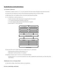
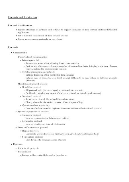
<strong><strong>Protocol</strong>s</strong> <strong>and</strong> <strong>Architecture</strong><strong>Protocol</strong> <strong>Architecture</strong>.• <strong>Layered</strong> <strong>structure</strong> of hardware <strong>and</strong> software to support exchange of data between systems/distributedapplications• Set of rules for transmission of data between systems• One or more common protocols for every layer<strong><strong>Protocol</strong>s</strong>• Characteristics– Direct/indirect communication∗ Point-to-point link· Two entities share a link, allowing direct communication· Entities may also connect through a number of intermediate hosts, bringing in the issue of accesscontrol, making the protocol more complex∗ Switched communications network· Entities depend on other entities for data exchange· Entities may be connected over local network (Ethernet) or may belong to different networks(internet)– Monolithic/<strong>structure</strong>d protocol∗ Monolithic protocol· All protocol logic (for every layer) is combined into one unit· Problem in changing any aspect of the protocol (such as virtual circuit request)∗ Structured protocol· Set of protocols with hierarchical/layered <strong>structure</strong>· Clearly shows the distinction between different layers of logic∗ Communications architecture· Hardware/software used to implement communications with <strong>structure</strong>d protocol– Symmetric/asymmetric protocol∗ Symmetric protocol· Involves communication between peer entities∗ Asymmetric protocol· Involves client/server type of relationship– St<strong>and</strong>ard/nonst<strong>and</strong>ard protocol• Functions∗ St<strong>and</strong>ard protocol· Commonly accepted protocols that have been agreed on by a st<strong>and</strong>ards body∗ Nonst<strong>and</strong>ard protocol· Built for specific communications situation– Basis for all protocols– Encapsulation∗ Data as well as control information in each pdu
<strong><strong>Protocol</strong>s</strong> <strong>and</strong> <strong>Architecture</strong> 11∗ Control information is divided into the following categories:1. Address of the sender <strong>and</strong> receiver2. Error detection code or frame check sequence3. <strong>Protocol</strong> control for other protocol functions– Segmentation <strong>and</strong> reassembly∗ Segment the data stream into small bounded size blocks or pdus∗ Reasons for segmentation· Communications network may accept data blocks only up to a certain size (53 octets for atm,1526 octets for Ethernet)· Efficient error control with smaller pdu size; fewer bits retransmitted in the event of failure· Better access to shared transmission facilities, with shorter delay; nobody can monopolize thenetwork· Smaller buffers at receiver stations· Can pause transfer for checkpoint <strong>and</strong> recovery∗ Disadvantages with segmentation· Larger overhead with smaller pdu size· More interrupts as pdus announce their arrival· More time spent to process smaller pdus∗ Segmented data is reassembled into messages appropriate for application level– Connection control∗ Connectionless data transfer· Each pdu is independent of other pdus∗ Connection-oriented data transfer· Used if stations are to be connected for long time or protocol details are to be worked out dynamically· Also known as logical association, or virtual circuit, with three phases1. Establish connection2. Transfer data3. Terminate connection∗ Establish connection· One station issues a connection request to the other, with or without involving a central authority· Receiver may accept or reject the connection· Request may include negotiating syntax, semantics, <strong>and</strong> timing of protocol· <strong>Protocol</strong> may have some options to be negotiated at connection time, such as pdu size∗ Transfer data· Exchange data <strong>and</strong> control information (flow control, error control)· Data flows in one direction while acknowledgements flow in the other∗ Terminate connection· Either side may terminate connection by sending a request· Connection may be terminated by a central authority∗ Sequencing· pdus are sequentially numbered as they are sent· Each side keeps track of outgoing numbers (generated locally), <strong>and</strong> incoming numbers (generatedby other host)– Ordered delivery∗ pdus may not arrive in order in which they are sent∗ Connection-oriented protocols require the pdu order to be maintained
<strong><strong>Protocol</strong>s</strong> <strong>and</strong> <strong>Architecture</strong> 14– Services between adjacent layers are expressed in terms of primitives <strong>and</strong> parameters– Primitive∗ Specifies the function to be performed– Parameters∗ Data <strong>and</strong> control information– Four types of primitives1. Request∗ Issued by a service user to invoke some service <strong>and</strong> to pass the parameters needed to fully specifythe service request2. Indication∗ Issued by the service provider to:(a) Indicate the the primitive has been invoked by the peer service user on the connection <strong>and</strong>provide associated parameters(b) Notify the service user of a provider-initiated action3. Response∗ Issued by a service user to acknowledge or complete some primitive previously invoked by anindication to that user4. Confirm∗ Issued by service provider to acknowledge or complete some primitive previously invoked by arequest by the service user– The time line indicates the sequence as specified above– Confirmed service∗ Initiator receives confirmation that the requested service has had the desired effect at the other end– Nonconfirmed service• osi layers∗ Initiator receives no confirmation that the requested service has been carried out1. Physical layer– Covers the physical interface between devices– Identifies the rules to pass bits from source to destination (raw bit stream service)– Four important characteristics(a) Mechanical∗ Physical properties of the interface to transmission medium(b) Electrical∗ Representation of bits in terms of voltage levels∗ Data transmission rates(c) Functional∗ Functions of individual circuits of physical interface between a system <strong>and</strong> transmission medium(d) Procedural∗ Sequence of events by which bit streams are exchanged2. Data link layer– Makes the physical link reliable, through error detection <strong>and</strong> control– Activates, maintains, <strong>and</strong> deactivates the link– Fully functional data link layer obviates the need for error control in higher layers– Communication through a number of data link layers may require the higher layers to perform someerror control
<strong><strong>Protocol</strong>s</strong> <strong>and</strong> <strong>Architecture</strong> 153. Network layer– Transfers information across communications network, performing switching <strong>and</strong> routing functions– Hides underlying data transmission <strong>and</strong> switching technologies– Highest layer in a network node– System interacts with network∗ Specification of destination address∗ Request for network services like priority– In direct point-to-point network, there is no need for network layer as data link layer manages thelink– Systems could be connected across a single network, using circuit switching or packet switchingtechniques∗ Packet level of X.25 st<strong>and</strong>ard4. Transport layer– Mechanism for exchange of data between end systems– Ensures that data are delivered error-free, in sequence, <strong>and</strong> with no losses or duplication– May optimize the use of network services– Provides a requested quality of service to session entities, based on acceptable error rates, maximumdelay, priority, <strong>and</strong> security– Size <strong>and</strong> complexity depend on the reliability of underlying layers5. Session layer– Mechanism to control the dialogue between applications in end systems– Key services include∗ Dialogue discipline· Full duplex or half duplex∗ Grouping· Mark data to define groups of data∗ Recovery· Checkpoint to allow retransmission of all data since last checkpoint due to failure6. Presentation layer– Format of data to be exchanged between applications– Defines syntax used between application entities– provides for selection <strong>and</strong> modification of the representation used– Data compression <strong>and</strong> encryption7. Application layer– Interface between application programs <strong>and</strong> osi environment– Management functions <strong>and</strong> other useful mechanisms for distributed applications supportTCP/IP protocol suite• Reasons for tcp/ip’s success– Time; appeared on the scene before the osi model– Support from the dod– Internet foundation• The tcp/ip approach
<strong><strong>Protocol</strong>s</strong> <strong>and</strong> <strong>Architecture</strong> 16– Modular <strong>and</strong> hierarchical like the osi model– Descriptive in nature compared to prescriptive nature of osi∗ Allows multiple protocol functionality in a single layer– Does not require strict use of all layers∗ Application level protocols may directly run on top of ip• Operation of tcp <strong>and</strong> ip– Computer is connected to network using a network access protocol such as ethernet∗ Enables host to send data across the network to another host or to a router to be transmitted toanother network– Internet protocol∗ Implemented in all the end systems <strong>and</strong> routers∗ Acts as a relay to move data from one host to another, possibly through router(s)– Transmission control protocol∗ Implemented in the end systems only∗ Keeps track of data blocks to ensure reliable delivery to appropriate applications– Two levels of addressing∗ Unique host address over global internet, used by ip∗ Unique process (port) address within host, used by tcp– tcp header∗ Control information for data blocks generated by user application∗ Items in the headerDestination port· Address to whom data is to be deliveredSequence number· Sequence number assigned to segment to keep track of segment order· Destination tcp entity may use it to reorder segmentsChecksum· Code to check error during transmission– ip datagram∗ Created by adding ip header to each segment∗ Items in header include destination host address∗ Presented to network access layer for transmission– Packet or frame• Applications∗ Created by network access layer by adding its own header to the ip datagram∗ Packet header contains information for network to transfer data across the network∗ Items in packet header areDestination network address· Device address for packet deliveryFacilities request· Request for use of network facilities, such as priority– Simple mail transfer protocol (smtp)∗ Basic email facility
<strong><strong>Protocol</strong>s</strong> <strong>and</strong> <strong>Architecture</strong> 17∗ Mechanism to transfer messages across hosts∗ Features include mailing lists, return receipts, <strong>and</strong> forwarding∗ Does not specify message creation; just the transfer of message using tcp– File transfer protocol (ftp)∗ Transfer files across systems under user comm<strong>and</strong>s∗ Can accommodate both text <strong>and</strong> binary files∗ Upon request, sets up a tcp connection to target system for exchange of control messages∗ Connection allows user to send authentication <strong>and</strong> files with desired file actions∗ Upon approval, a second tcp connection is opened for actual data transfer∗ Second connection avoids the overhead of control information at the application level∗ After file transfer is complete, control connection is used to signal completion <strong>and</strong> accept new comm<strong>and</strong>s– Telnet∗ Remote logon capability∗ Designed to work with simple scroll-mode terminals∗ Implemented in two modules1. User telnet· Interacts with terminal I/O module to communicate with a local terminal· Converts characteristics of real terminals to network st<strong>and</strong>ards <strong>and</strong> vice versa2. Server telnet· Interacts with an application, acting as a surrogate terminal h<strong>and</strong>ler· Makes remote terminal appear as local to the application∗ Traffic between user <strong>and</strong> server telnet is carried on a tcp connection