Balancing Inverted Pendulum by Angle Sensing Using Fuzzy Logic ...
Balancing Inverted Pendulum by Angle Sensing Using Fuzzy Logic ...
Balancing Inverted Pendulum by Angle Sensing Using Fuzzy Logic ...
- No tags were found...

You also want an ePaper? Increase the reach of your titles
YUMPU automatically turns print PDFs into web optimized ePapers that Google loves.
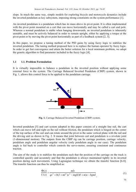
Sensors & Transducers Journal, Vol. 133, Issue 10, October 2011, pp. 74-82slope. In much the same way, simple models for exploring bicycle and motorcycle dynamics includethe inverted pendulum as key subsystem, imposing strong constraints on the system performance [1].An inverted pendulum is a pendulum which has its mass above its pivot point. It is often implementedwith the pivot point mounted on a cart that can move horizontally and may be called a cart and pole.Whereas a normal pendulum is stable when hanging downwards, an inverted pendulum is inherentlyunstable, and must be actively balanced in order to remain upright, either <strong>by</strong> applying a torque at thepivot point or <strong>by</strong> moving the pivot point horizontally as part of a feedback system [2, 3].In this paper, we propose a tuning method of the PID gains <strong>by</strong> using fuzzy logic to stabilize theinverted pendulum. The tuning method proposed here is to replace the human operator <strong>by</strong> fuzzy logic.In order to get fast convergence and attain the better solution for a local minimum problem, we adoptthe genetic algorithm to find parameter included in the fuzzy logic [4].1.1 1.1. Problem FormulationIt is virtually impossible to balance a pendulum in the inverted position without applying someexternal force to the system. The Carriage Balanced <strong>Inverted</strong> <strong>Pendulum</strong> (CBIP) system, shown inFig. 1, allows this control force to be applied to the pendulum carriage.Fig. 1. Carriage Balanced <strong>Inverted</strong> <strong>Pendulum</strong> (CBIP) system.<strong>Inverted</strong> pendulum [5] and cart system adopted in this paper consists of a straight line rail, the cartwhich can move left and right on the rail without friction, the pendulum which is hinged on the centerof the top surface of the cart and can rotate around the pivot in the same vertical plane with the rail andthe driving unit as shown in Fig. 2. It means that joint between cart and pendulum is a revolute joint(1-dimensional motion). The outputs from the CBIP rig can be carriage position, carriage velocity,pendulum angle and pendulum angular velocity (only pendulum angle in our case). The pendulumangle is fed back to controller which controls the servo-motor, ensuring consistent and continuoustraction.The aim of the study is to stabilize the pendulum such that the position of the carriage on the track iscontrolled quickly and accurately and that the pendulum is always maintained tightly in its invertedposition during such movements. <strong>Using</strong> Lagrangian technique we obtain the transfer function [6-8].The transfer function can thus be simplified as:(s)U(s)qs3 b(I ml2) s2mls mgl(M m)s bgml,(1)75