AW000873 Installation Guide for Energate Thermostats
AW000873 Installation Guide for Energate Thermostats
AW000873 Installation Guide for Energate Thermostats
Create successful ePaper yourself
Turn your PDF publications into a flip-book with our unique Google optimized e-Paper software.
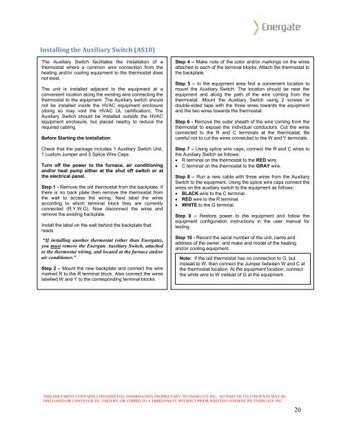
Installing the Auxiliary Switch (AS10)<br />
The Auxiliary Switch facilitates the installation of a<br />
thermostat where a common wire connection from the<br />
heating and/or cooling equipment to the thermostat does<br />
not exist.<br />
The unit is installed adjacent to the equipment at a<br />
convenient location along the existing wire connecting the<br />
thermostat to the equipment. The Auxiliary switch should<br />
not be installed inside the HVAC equipment enclosure<br />
(doing so may void the HVAC UL certification). The<br />
Auxiliary Switch should be installed outside the HVAC<br />
equipment enclosure, but placed nearby to reduce the<br />
required cabling.<br />
Be<strong>for</strong>e Starting the <strong>Installation</strong><br />
Check that the package includes 1 Auxiliary Switch Unit,<br />
1 custom Jumper and 5 Splice Wire Caps.<br />
Turn off the power to the furnace, air conditioning<br />
and/or heat pump either at the shut off switch or at<br />
the electrical panel.<br />
Step 1 - Remove the old thermostat from the backplate. If<br />
there is no back plate then remove the thermostat from<br />
the wall to access the wiring. Next label the wires<br />
according to which terminal block they are currently<br />
connected (R,Y,W,G). Now disconnect the wires and<br />
remove the existing backplate.<br />
Install the label on the wall behind the backplate that<br />
reads<br />
“If installing another thermostat (other than <strong>Energate</strong>),<br />
you must remove the <strong>Energate</strong> Auxiliary Switch, attached<br />
to the thermostat wiring, and located at the furnace and/or<br />
air conditioner.”<br />
Step 2 – Mount the new backplate and connect the wire<br />
marked R to the R terminal block. Also connect the wires<br />
labelled W and Y to the corresponding terminal blocks.<br />
Step 4 – Make note of the color and/or markings on the wires<br />
attached to each of the terminal blocks. Attach the thermostat to<br />
the backplate.<br />
Step 5 – In the equipment area find a convenient location to<br />
mount the Auxiliary Switch. The location should be near the<br />
equipment and along the path of the wire coming from the<br />
thermostat. Mount the Auxiliary Switch using 2 screws or<br />
double-sided tape with the three wires towards the equipment<br />
and the two wires towards the thermostat.<br />
Step 6 - Remove the outer sheath of the wire coming from the<br />
thermostat to expose the individual conductors. Cut the wires<br />
connected to the R and C terminals at the thermostat. Be<br />
careful not to cut the wires connected to the W and Y terminals.<br />
Step 7 – Using splice wire caps, connect the R and C wires to<br />
the Auxiliary Switch as follows:<br />
• R terminal on the thermostat to the RED wire.<br />
• C terminal on the thermostat to the GRAY wire.<br />
Step 8 – Run a new cable with three wires from the Auxiliary<br />
Switch to the equipment. Using the splice wire caps connect the<br />
wires on the auxiliary switch to the equipment as follows:<br />
• BLACK wire to the C terminal.<br />
• RED wire to the R terminal.<br />
• WHITE to the G terminal.<br />
Step 9 – Restore power to the equipment and follow the<br />
equipment configuration instructions in the user manual <strong>for</strong><br />
testing.<br />
Step 10 - Record the serial number of the unit, name and<br />
address of the owner, and make and model of the heating<br />
and/or cooling equipment.<br />
Note: If the old thermostat has no connection to G, but<br />
instead to W, then connect the Jumper between W and C at<br />
the thermostat location. At the equipment location, connect<br />
the white wire to W instead of G at the equipment.<br />
THIS DOCUMENT CONTAINS CONFIDENTIAL INFORMATION PROPRIETARY TO ENERGATE INC. NO PART OF ITS CONTENTS MAY BE<br />
DISCLOSED OR CONVEYED TO, USED BY, OR COPIED TO A THIRD PARTY WITHOUT PRIOR WRITTEN CONSENT BY ENERGATE INC.<br />
20


