WACC-01 Flow Controls & Accessories - Watts Fluid Air
WACC-01 Flow Controls & Accessories - Watts Fluid Air
WACC-01 Flow Controls & Accessories - Watts Fluid Air

Create successful ePaper yourself
Turn your PDF publications into a flip-book with our unique Google optimized e-Paper software.
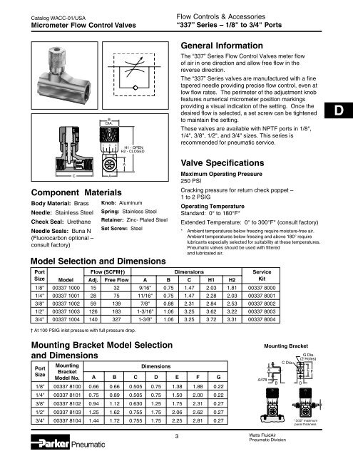
Catalog <strong>WACC</strong>-<strong>01</strong>/USAMicrometer <strong>Flow</strong> Control Valves<strong>Flow</strong> <strong>Controls</strong> & <strong>Accessories</strong>“337” Series – 1/8" to 3/4" PortsBody Material: BrassNeedle: Stainless SteelCheck Seal: UrethaneNeedle Seals: Buna N(Fluorocarbon optional –consult factory)CKnob: AluminumSpring: Stainless SteelRetainer: Zinc- Plated SteelSet Screw: SteelModel Selection and Dimensions1BDIA.10 9Component MaterialsAH1 - OPENH2 - CLOSEDAGeneral InformationThe “337” Series <strong>Flow</strong> Control Valves meter flowof air in one direction and allow free flow in thereverse direction.The “337” Series valves are manufactured with a finetapered needle providing precise flow control, even atlow flow rates. The perimeter of the adjustment knobfeatures numerical micrometer position markingsproviding a visual indication of the setting. Once thedesired flow is selected, a set screw can be tightenedto maintain the setting.These valves are available with NPTF ports in 1/8",1/4", 3/8", 1/2", and 3/4" sizes. This series isrecommended for pneumatic service.Valve SpecificationsMaximum Operating Pressure250 PSICracking pressure for return check poppet –1 to 2 PSIGOperating TemperatureStandard: 0° to 180°F*Extended Temperature: 0° to 300°F* (consult factory)* Ambient temperatures below freezing require moisture-free air.Ambient temperatures below freezing and above 180° requirelubricants especially selected for suitability at these temperatures.Pneumatic valves should be used with filteredand lubricated air.Port <strong>Flow</strong> (SCFM†) Dimensions ServiceSize Model Adj. Free <strong>Flow</strong> A B C H1 H2 Kit1/8" 00337 1000 15 32 9/16" 0.75 1.47 2.03 1.81 00337 800<strong>01</strong>/4" 00337 10<strong>01</strong> 28 75 11/16" 0.75 1.47 2.28 2.03 00337 80<strong>01</strong>3/8" 00337 1002 59 139 7/8" 0.88 2.31 2.84 2.53 00337 80021/2" 00337 1003 126 183 1-3/16" 1.06 3.25 3.62 3.22 00337 80033/4" 00337 1004 140 327 1-3/8" 1.06 3.25 3.72 3.31 00337 8004CD† At 100 PSIG inlet pressure with full pressure drop.Mounting Bracket Model Selectionand DimensionsMountingPortDimensionsBracketSizeModel No. A B C D E F G1/8" 00337 8100 0.66 0.66 0.505 0.75 1.38 1.88 0.221/4" 00337 81<strong>01</strong> 0.75 0.89 0.505 0.75 1.50 2.00 0.223/8" 00337 8102 0.94 1.12 0.630 1.25 1.75 2.31 0.271/2" 00337 8103 1.25 1.62 0.755 1.75 2.06 2.62 0.273/4" 00337 8104 1.44 1.72 0.755 1.75 2.25 2.81 0.27.0478Mounting BracketA11BC Dia.G Dia.(2 Holes)D0 9 11E F0 9* 3/32" maximumpanel thickness*Pneumatic3 <strong>Watts</strong> <strong>Fluid</strong><strong>Air</strong>Pneumatic Division