July - Home Metal Shop Club
July - Home Metal Shop Club
July - Home Metal Shop Club

Create successful ePaper yourself
Turn your PDF publications into a flip-book with our unique Google optimized e-Paper software.
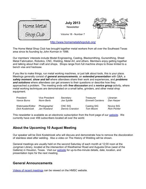
<strong>July</strong> 2013 - <strong>Home</strong> <strong>Metal</strong> <strong>Shop</strong> <strong>Club</strong> Newsletter - V. 18 No. 5Here is the link to Dick’s presentation slides.3
<strong>July</strong> 2013 - <strong>Home</strong> <strong>Metal</strong> <strong>Shop</strong> <strong>Club</strong> Newsletter - V. 18 No. 5Safety MomentAlan May warned members about over pressuring see-through tanks to test for leaks. There is a risk ofexceeding the elastic limit of the tank's material.Vance Burns explained why welding cylinders are hydrostatically tested rather than pneumaticallytested. A failure of a cylinder under hydrostatic testing would leak water, since water, the usual fluid forhydrostatic testing, is for all practical purposes incompressible. A failure of a cylinder under pneumatictesting would lead to catastrophic consequences, since air, the typical medium for pneumatic testing, iscompressible.Show and TellDick Kostelnicek has a face mill cutter with a negative rake. He haddifficulty tightening the bolt that secures the cutter head to a R8 arbor.Dick made a tool having four silver soldered projections on an annealedhex nut socket to facilitate tightening securing bolt (left photo).Joe Williams brought in twotools from his extensivecollection. One was a screwholder with a tapered shaft togrip a screw (right photo).The other was a screw pitch gage with an attached 60 degreecenter gauge (above right photo).Martin Kennedy talked about two projects. The first was an Aloristypetool holder for a new Iscar cut-off tool (left photo). When hemade the holder, he accidentally drilled a hole in the wrong place.He described how he plugged the hole with a threaded rod afterapplying permanent thread locking compound. He then re-drilledand tapped the hole in the correct location. See (www.aloris.com).4
<strong>July</strong> 2013 - <strong>Home</strong> <strong>Metal</strong> <strong>Shop</strong> <strong>Club</strong> Newsletter - V. 18 No. 5The secondproject wasmaking threequick-connect toolholders for theRoyal Quick-Change ToolSystem on hismill. Thedimensions of the tool’s tapered arbor were critical for a tight fit,and were very hard to measure. Martin made a gauge todetermine the geometry of the tool holder, and kept modifying ituntil it exactly fit a commercially made tool holder. He thenmade three tools - a drill chuck holder (upper left), a cut-off sawholder (upper right photo), and a fly cutter (right photo) using thegauge to check dimensions while machining the tools. All threefit accurately the first time, without the need for furthermachining. See (www.royalprod.com).Alan May brought in hismodel engine calledthe 'Farm Boy Hit andMiss 4-Cycle Engine'designed by www.jerryhowell.com.This littleengine runs onacetone, and Alan builtit from the model plans.Alan spared no detail,as one can see fromthe picture. Theengine is designed touse an 'O' ring on thepiston instead ofnormal cast iron pistonrings. Without a load,the Farm Boy will turnbetween 20 to 30revolutions between Hitand Miss firings.5
<strong>July</strong> 2013 - <strong>Home</strong> <strong>Metal</strong> <strong>Shop</strong> <strong>Club</strong> Newsletter - V. 18 No. 5Dan Harper talked about two projects. The first was making a onedegree taper for a driver head under construction. The second wasmaking taller jaws for his vice.Problems and Solutions - Ask the BlacksmithA member said that he had a problem with ascertaining the force exerted by his hydraulicpress. One solution offered was to use a load cell to directly measure the cell’s pressure alongwith its area. Multiplying the pressure by the load cell’s piston area gives the force exerted. Ifan arbor press is employed, then the force is the determined from the force applied to end ofthe handle (moment arm) times the ratio of the handle length divided by the rack gear’s radius.Another member had some tallow tree stumps to remove and was having difficulties making ahomemade stump grinder. He used the body and motor of an unused hand grinder. A cut-offsaw attached to the shaft of the motor proved no match for the tough tallow tree stumps. Themotor would run for about two minutes and then stop. It appears the motor lacked sufficienttorque to cut through the stump. Solutions offered were renting a stump grinder and fillingholes in the stump with nitrogen fertilizer to rot the stump.One member requested ideas on how to clean a welder's leather apron. He did not want tosend the leathers to a dry cleaner because the costs to dry clean would be more that the dealhe got at the garage sale. Cleaning suggestions varied from using soaking in odorless whitegas to using soap and water.Novice SIG ActivitiesRich Pichler and the novice group demonstrated a portable welder and assorted weldingsupplies.Articles6
<strong>July</strong> 2013 - <strong>Home</strong> <strong>Metal</strong> <strong>Shop</strong> <strong>Club</strong> Newsletter - V. 18 No. 5Engraving Tool Drive AssemblyBy J. R. WilliamsThis project started when I was given anold spindle unit from a commercialengraving machine (New Hermes). NowI have a spindle unit with a dull engravingtool and no way to drive the unit. Mymilling machine is capable of around3500 RPM and this is not enough for asmall engraving cutter. The next movewas to devise a way to drive the unit withmy milling machine. The drive’s largepulley started as 5 inch diameter bar andhas a ¾-inch shaft that goes into thecollet holder. The pulley finished out at4.226-inch in diameter and the quill drivepulley on the engraving unit is 0.816-inchdiameter. The result: a spindle speed of18,125 RPM with a mill speed of 3500RPM.The supporting assembly is clamped tothe lower bearing flange on the mill’squill. This flange is about 5/16-inch largerin diameter that the quill. A 1-1/4-inchaluminum cylinder attaches to the upperclamp and to a section of 2-inchaluminum angle. A rectangular block ofaluminum was bored to hold the spindle housing and mounts to the aluminum angle. The engravingspindle unit has an adjustable nose so it can contact the surface of the work to maintain a uniformdepth of cut. On the front side of the spindle block, there is a spring holder that pushes down on thequill assembly. No dimensions are given as the parts will change with different mills and spindle unit.The first operation at driving the spindle was with the smooth side of a small timing belt but there wastoo much vibration. So, the purchase of a small width endless belt was necessary. An “O” ring wastried as a belt but it could not handle the high speed.Machining the large clamp unit was an ordeal. After the clamp unit was machined and the installationprocess started there was a big surprise - it was too big. I had made it one inch too large in diameter.There is a lot of work in the clamp assembly as it has two small flanges that fit over the quill flange foralignment and to prevent it falling off.The spindle unit can be used with the installed nose section to limit the cutter depth or it can be fixed inorder to allow the mill setting to determine the depth of cut.This has been an interesting project.7
<strong>July</strong> 2013 - <strong>Home</strong> <strong>Metal</strong> <strong>Shop</strong> <strong>Club</strong> Newsletter - V. 18 No. 5Repair Your Portable WelderBy Joe SybilleAn inoperative portable welder need not remain so. Remove thecover(s) and turn it on. Exercise caution around live circuits.Listen for strange sounds and be aware of unusual odors. Lookfor obvious problems such as components that appear discoloredor broken. Now, with the power off, use an ohm-meter to checkthe continuity of components such as resistors, diodes, transistors,relays, etc.In my case, I had a Lincoln Weld-Pak 100 welder (left photo) witha feed motor that would not rotate to advance the electrode wire.Connecting 12 volts DC directly to the motor revealed that itworked, so the problem had to be in the electronic circuitry thatdrives the motor. Examining the wires and components on thecircuit board revealed a cracked (open circuited) 2.7 ohm cement(wire wound) resistor and a burned (abnormally high resistance)33K carbon composition resistor (photo below). I replaced thesetwo components, re-installed the printed circuit board, and turnedon the welder. Replacing those components resolved theproblem.Methodical checking of components was the key to resolving mywelder problems. The same process may work for you.8