

Ground fault monitor RCM420 - Bender
Ground fault monitor RCM420 - Bender
Ground fault monitor RCM420 - Bender

Create successful ePaper yourself
Turn your PDF publications into a flip-book with our unique Google optimized e-Paper software.
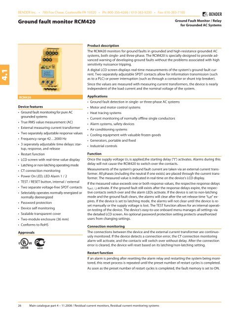
BENDER Inc. • 700 Fox Chase, Coatesville PA 19320 • Ph: 800-356-4266 / 610-383-9200 • Fax: 610-383-7100<strong>Ground</strong> <strong>fault</strong> <strong>monitor</strong> <strong>RCM420</strong><strong>Ground</strong> Fault Monitor / Relayfor <strong>Ground</strong>ed AC Systems4.1Product descriptionThe <strong>RCM420</strong> <strong>monitor</strong>s for ground <strong>fault</strong>s in grounded and high-resistance grounded ACsystems, both single- and three-phase. The <strong>RCM420</strong> is specially designed to provide advancedwarning of developing ground <strong>fault</strong>s without the problems associated with highsensitivity nuissance tripping.A digital LCD screen displays real-time measurements of the system's ground <strong>fault</strong> current.Two separately adjustable SPDT contacts allow for information transmission (suchas to a PLC) or power interruption (such as through a contactor or shunt trip breaker).Since the values are measured with measuring current trans formers, the device is nearlyindependent of the load current and the nominal voltage of the system.<strong>RCM420</strong>Device features• <strong>Ground</strong> <strong>fault</strong> <strong>monitor</strong>ing for pure ACgrounded systems• True RMS value measurement (AC)• External measuring current transformer• Two separately adjustable response values• Frequency range 42…2000 Hz• 3 seperately adjustable time delays: startup,response, and release• Restart function• LCD screen with real-time value display• Latching or non-latching operating mode• CT connection <strong>monitor</strong>ing• Power On LED, LED Alarm 1 / 2• TEST / RESET button, internal / external• Two separate voltage-free SPDT contacts• Selectably operates normally energized ornormally deenergized• Password protection• Device self <strong>monitor</strong>ing• Sealable transparent cover• Two-module enclosure (36 mm)• Conforms to RoHSApprovalsApplications• <strong>Ground</strong> <strong>fault</strong> detection in single- or three-phase AC systems• Motor and motor control systems• Heat tracing systems• Current <strong>monitor</strong>ing of normally offline single conductors• Alarm systems, safety devices• Air conditioning systems• Cooling equipment with valuable frozen goods• Generators, portable and fixed• Industrial controlsFunctionOnce the supply voltage U S is applied,the starting delay ("t") activates. Alarms during thisdelay will not cause the <strong>RCM420</strong> to switch over the contacts.Measurements of the system's ground <strong>fault</strong> current are taken via an external current transformer.All phases (including the neutral if one exists) are placed through the current transformer.The measured value is indicated in real-time on the device's LCD display.If the measured value exceeds one or both response values, the respective response delayst on1 / 2 activate. If the ground <strong>fault</strong> still exists after the response delays expire, the respectivecontacts switch over and the alarm LEDs activate. If the device is set to non-latchingmode and the ground <strong>fault</strong> clears, the alarms will clear after the set release time “t off” expires.If the device is set to latching mode, the alarms will not clear until the device is resetmanually or the supply voltage is lost. The TEST function allows for an internal operationtesting of the device. The device's easy-to-use onboard menu manages all settings viathe detailed LCD screen. An optional password protection setting protects unauthorizedusers from changing settings.Connection <strong>monitor</strong>ingThe connections between the device and the external current transformer are continuously<strong>monitor</strong>ed. If the device detects a connection error, the CT connection <strong>monitor</strong>ingalarm will activate, and the contacts will switch over without delay. After the connectionerror is cleared, the device will reset based on its latching/non-latching setting.Restart functionIf an alarm is pending after resetting the alarm relay and restarting the system being <strong>monitor</strong>ed,this reset process is repeated until the preset number of restart cycles is completed.As soon as the preset number of restart cycles is completed, the <strong>fault</strong> memory is set to ON.26 Main catalogue part 4 – 11.2008 / Residual current <strong>monitor</strong>s, Residual current <strong>monitor</strong>ing systems
Residual current <strong>monitor</strong> <strong>RCM420</strong>Operating and display elementsWiring diagram12 34.14*2156 731 - Power “ON” LED (green): Illuminates when power is receivedto the unit. Flashes when the current transformer connectionalarm is active.2 - Alarm LED “AL1” (yellow): Alarm 1, illuminates when the setres ponse value I Δn1 has been exceeded. Flashes when thecurrent transformer connection alarm is active.3 - Alarm LED “AL2” (yellow): Alarm 2, illuminates when the setresponse value I Δn2 has been exceeded. Flashes when thecurrent transformer connection alarm is active.4 - Multi-functional LCD display5 - TEST button: Activates self-testArrow up key: Scrolls up inside device's menu6 - RESET button: Resets deviceArrow down key: Scrolls down inside device's menu7 - MENU key: Activates device's internal menuEnter key: Confirm change inside device's menuEscape key (held > 1.5 s): Goes back a step inside menu51 - External supply voltage used to power devicea 6 A fuse recommended for internal short circuit protection.2 - Connection to external current transformer. All phases,including the neutral if one exists, are placed through thecurrent transformer.3 - Alarm relay K1: programmable for I Δn1 / I Δn2 / TEST / ERROR4 - Alarm relay K2: programmable for I Δn1 / I Δn2 / TEST / ERROR5 - Combined external TEST and RESET button4* - When shielded cabling is used.Note: Do not route the ground conductor through the measuringcurrent transformer when also routing the power conductors!Main catalogue part 4 – 11.2008 / Residual current <strong>monitor</strong>s, Residual current <strong>monitor</strong>ing systems 27
Residual current <strong>monitor</strong> <strong>RCM420</strong>External measuring current transformersType Inside diameter (mm) Art. No.W20 ø 20 B 9808 0003W35 ø 35 B 9808 0010W60 ø 60 B 9808 0018W120 ø 120 B 9808 0028W210 ø 210 B 9808 0034WR70x175 70 x 175 B 9808 0609WR115x305 115 x 305 B 9808 0610WS20x30 20 x 30 B 9808 0601WS50x80 50 x 80 B 9808 0603WS80x120 80 x 120 B 9808 0606Other measuring current transformer types on request.Dimension diagram XM420Dimensions in mmOpen the front plate cover indirection of arrow!Screw mountingNote: The upper mounting clipmust be ordered separately(see ordering information).4.1AccessoriesTypeArt. No.Mounting clip for enclosure XM420B 9806 0008(1 piece per device)Snap-on mounting for W20… / W35… B 9808 0501Snap-on mounting for W60… B 9808 0502Ordering information: <strong>RCM420</strong> (standard models)TypeResponseFrequencyMeasuring currentSupply voltage US*Art. No.range I Δnrangetransformers<strong>RCM420</strong>-D-1 10 mA…10 A 42…2000 Hz W…, WR…, WS… DC 9.6…94 V / AC 42…460 Hz 16…72 V B 9401 4001<strong>RCM420</strong>-D-2 10 mA…10 A 42…2000 Hz W…, WR…, WS… DC 70…300 V / AC 42…460 Hz 70…300 V B 9401 4002* absolute valuesOrdering information: <strong>RCM420</strong> (ordering guide for all models)R C M 4 2 0 - D M - 21 2Code 1: Contact / analog outputs (optional)Modifier Contact 1 Contact 2Nothing Alarm contact Alarm contact"M" All analog outputs* --"M1C" 0(4)…20 mA Alarm contact"M2C" 0…400 μA Alarm contact"M3C" 0…10 V Alarm contact* selectable between 0(4)...20 mA, 0...400 μA, 0...10 VCode 2: Auxiliary supply voltageModifier Supply voltage U S*"1" DC 9.6…94 V / AC 42…460 Hz 16…72 V"2" DC 70…300 V / AC 42…460 Hz 70…300 V* absolute valuesMain catalogue part 4 – 11.2008 / Residual current <strong>monitor</strong>s, Residual current <strong>monitor</strong>ing systems 29


