- Page 1 and 2: protectionand control
- Page 3 and 4: 2 protection guide Merlin Gerin
- Page 5 and 6: grounding systems (cont.)ungrounded
- Page 7 and 8: grounding systems (cont.)reactance
- Page 9 and 10: 8 protection guide Merlin Gerin
- Page 11 and 12: short-circuit currents (cont.)phase
- Page 13 and 14: short-circuit currents (cont.)equip
- Page 15 and 16: 14 protection guide Merlin Gerin
- Page 17 and 18: discrimination (cont.)time discrimi
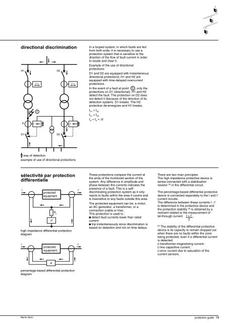
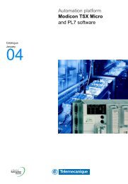
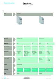
- Page 19: discrimination (cont.)logic selecti
- Page 23 and 24: electrical system protection (cont.
- Page 25 and 26: electrical system protection (cont.
- Page 27 and 28: electrical system protection (cont.
- Page 29 and 30: 28 protection guide Merlin Gerin
- Page 31 and 32: transformer protection (cont.)prote
- Page 33 and 34: transformer protection (cont.)setti
- Page 35 and 36: 34 protection guide Merlin Gerin
- Page 37 and 38: motor protection (cont.)motor prote
- Page 39 and 40: motor protection (cont.)setting inf
- Page 41 and 42: 40 protection guide Merlin Gerin
- Page 43 and 44: AC generator protection (cont.)prot
- Page 45 and 46: AC generator protection (cont.)exam
- Page 47 and 48: 46 protection guide Merlin Gerin
- Page 49 and 50: capacitor protection (cont.)protect
- Page 51 and 52: capacitor protection (cont.)setting
- Page 53 and 54: 52 protection guide Merlin Gerin
- Page 55 and 56: sensors (cont.)CT responsein satura
- Page 57 and 58: sensors (cont.)voltage transformers
- Page 59 and 60: ContentspageRS 485 network 22-wire
- Page 61 and 62: 4-wire bus topologyFor 4-wire conne
- Page 63 and 64: Sepam 1000 + communicationinterface
- Page 65 and 66: CCA 600-29-pin connectors56,4 16The
- Page 67 and 68: CommissioningParameter setting of s
- Page 69 and 70: CommissioningAC or DC power supplyA
- Page 71 and 72:
Connection of “master” stationA
- Page 73 and 74:
Master station in RS 232with ACE 90
- Page 75 and 76:
Connection of “slave” stations
- Page 77 and 78:
Master station in RS 232with ACE 91
- Page 79 and 80:
Extension of the RS 485 network wit
- Page 81 and 82:
TroubleshootingOperating problemsIn
- Page 83 and 84:
Sepam 2000 diagnosis guideContentsp
- Page 85 and 86:
Sepam 2000 diagnosis guide (cont’
- Page 87 and 88:
Sepam 2000 diagnosis guide (cont’
- Page 89 and 90:
Sepam 2000 diagnosis guide (cont’
- Page 91 and 92:
Sepam 2000 diagnosis guide (cont’
- Page 93 and 94:
Sepam 2000 diagnosis guide (cont’
- Page 95 and 96:
Sepam 1000 diagnosis guideAll indic
- Page 97 and 98:
Sepam 1000 diagnosis guide (cont’
- Page 99 and 100:
Sepam 1000 diagnosis guide (cont’
- Page 101 and 102:
TRANSFORMER PROTECTION! Protection
- Page 103 and 104:
TRANSFORMER PROTECTION! Main charac
- Page 105 and 106:
TRANSFORMER PROTECTIONIAAIBBICC! Ma
- Page 107 and 108:
TRANSFORMER PROTECTION100t (s)! I <
- Page 109 and 110:
Overcurrent (inst)Earth fault (inst
- Page 111 and 112:
TRANSFORMER PROTECTIONI ctPeak valu
- Page 113 and 114:
TRANSFORMER PROTECTION! Overcurrent
- Page 115 and 116:
TRANSFORMER PROTECTION! Thermal ove
- Page 117 and 118:
TRANSFORMER PROTECTION! Thermal ove
- Page 119 and 120:
TRANSFORMER PROTECTION! Residual ov
- Page 121 and 122:
IccAIsATRANSFORMER PROTECTIONPhase
- Page 123 and 124:
TRANSFORMER PROTECTIONPhase directi
- Page 125 and 126:
TRANSFORMER PROTECTIONPhase directi
- Page 127 and 128:
TRANSFORMER PROTECTIONDirectional e
- Page 129 and 130:
TRANSFORMER PROTECTIONDirectional e
- Page 131 and 132:
TRANSFORMER PROTECTIONDirectional e
- Page 133 and 134:
TRANSFORMER PROTECTIONDirectional e
- Page 135 and 136:
TRANSFORMER PROTECTION! Restricted
- Page 137 and 138:
TRANSFORMER PROTECTIONUndervoltage
- Page 139 and 140:
TRANSFORMER PROTECTION! Remanent un
- Page 141 and 142:
TRANSFORMER PROTECTIONItIdIh2Ih5IdI
- Page 143 and 144:
idh2TRANSFORMER PROTECTIONArtificia
- Page 145 and 146:
TRANSFORMER PROTECTIONS2000D is sen
- Page 147 and 148:
TRANSFORMER PROTECTIONSimplified ch
- Page 149 and 150:
BUSBAR PROTECTION! Logic discrimina
- Page 151 and 152:
Overcurrent (inst)Earth fault (inst
- Page 153 and 154:
BUSBAR PROTECTION! High impedance d
- Page 155 and 156:
BUSBAR PROTECTION! High impedance d
- Page 157 and 158:
BUSBAR PROTECTIONIncomer! Percentag
- Page 159 and 160:
BUSBAR PROTECTION! Percentage diffe
- Page 161 and 162:
BUSBAR PROTECTION! Rate Of Change O
- Page 163 and 164:
BUSBAR PROTECTION! Rate Of Change O
- Page 165 and 166:
BUSBAR PROTECTION! Synchro-check (2
- Page 167 and 168:
SUBSTATION PROTECTION
- Page 169 and 170:
SUBSTATION PROTECTION! Logic discri
- Page 171 and 172:
SUBSTATION PROTECTION! Overcurrent
- Page 173 and 174:
SUBSTATION PROTECTIONI ctPeak value
- Page 175 and 176:
SUBSTATION PROTECTION! Earth fault
- Page 177 and 178:
SUBSTATION PROTECTIONUndervoltage (
- Page 179 and 180:
SUBSTATION PROTECTION! Overvoltage
- Page 181 and 182:
SUBSTATION PROTECTION! Phase direct
- Page 183 and 184:
IccAIsASUBSTATION PROTECTIONPhase d
- Page 185 and 186:
SUBSTATION PROTECTIONPhase directio
- Page 187 and 188:
SUBSTATION PROTECTIONPhase directio
- Page 189 and 190:
SUBSTATION PROTECTION! Directional
- Page 191 and 192:
SUBSTATION PROTECTIONDirectional ea
- Page 193 and 194:
SUBSTATION PROTECTIONDirectional ea
- Page 195 and 196:
SUBSTATION PROTECTIONDirectional ea
- Page 197 and 198:
SUBSTATION PROTECTIONDirectional ea
- Page 199 and 200:
SUBSTATION PROTECTION! Rate Of Chan
- Page 201 and 202:
RING NETWORK PROTECTION
- Page 203 and 204:
CLOSED RING NETWORK PROTECTIONsourc
- Page 205 and 206:
CAPACITOR PROTECTION! Logic discrim
- Page 207 and 208:
CAPACITOR PROTECTIONOvercurrent (in
- Page 209 and 210:
CAPACITOR PROTECTIONE! Thermal over
- Page 211 and 212:
MOTOR PROTECTION
- Page 213 and 214:
ASYNCHRONOUS MOTOR PROTECTION! MAIN
- Page 215 and 216:
ASYNCHRONOUS MOTOR PROTECTION! Cont
- Page 217 and 218:
ASYNCHRONOUS MOTOR PROTECTIONOvercu
- Page 219 and 220:
ASYNCHRONOUS MOTOR PROTECTIONI ctPe
- Page 221 and 222:
ASYNCHRONOUS MOTOR PROTECTION! Over
- Page 223 and 224:
ASYNCHRONOUS MOTOR PROTECTION! Ther
- Page 225 and 226:
ASYNCHRONOUS MOTOR PROTECTIONt10010
- Page 227 and 228:
ASYNCHRONOUS MOTOR PROTECTION! Ther
- Page 229 and 230:
ASYNCHRONOUS MOTOR PROTECTION! Numb
- Page 231 and 232:
ASYNCHRONOUS MOTOR PROTECTION! Exce
- Page 233 and 234:
ASYNCHRONOUS MOTOR PROTECTION! Exce
- Page 235 and 236:
ASYNCHRONOUS MOTOR PROTECTION! Unde
- Page 237 and 238:
ASYNCHRONOUS MOTOR PROTECTIONPositi
- Page 239 and 240:
ASYNCHRONOUS MOTOR PROTECTIONDirect
- Page 241 and 242:
ASYNCHRONOUS MOTOR PROTECTIONDirect
- Page 243 and 244:
ASYNCHRONOUS MOTOR PROTECTIONDirect
- Page 245 and 246:
ASYNCHRONOUS MOTOR PROTECTION! Moto
- Page 247 and 248:
SYNCHRONOUS MOTOR PROTECTION! Real
- Page 249 and 250:
GENERATOR PROTECTION! Generalities
- Page 251 and 252:
GENERATOR PROTECTION : Single gener
- Page 253 and 254:
GENERATOR PROTECTION : Single block
- Page 255 and 256:
GENERATOR PROTECTIONPhase faults! C
- Page 257 and 258:
GENERATOR PROTECTION67 (inst)! Logi
- Page 259 and 260:
GENERATOR PROTECTIONI ctPeak valueR
- Page 261 and 262:
GENERATOR PROTECTION! Overcurrent (
- Page 263 and 264:
GENERATOR PROTECTION! Earth fault (
- Page 265 and 266:
QGENERATOR PROTECTION : Reverse rea
- Page 267 and 268:
GENERATOR PROTECTIONE! Thermal over
- Page 269 and 270:
GENERATOR PROTECTION! Negative sequ
- Page 271 and 272:
IccAIsAGENERATOR PROTECTIONPhase di
- Page 273 and 274:
GENERATOR PROTECTIONPhase direction
- Page 275 and 276:
GENERATOR PROTECTIONPhase direction
- Page 277 and 278:
GENERATOR PROTECTIONDirectional ear
- Page 279 and 280:
GENERATOR PROTECTIONDirectional ear
- Page 281 and 282:
GENERATOR PROTECTIONDirectional ear
- Page 283 and 284:
GENERATOR PROTECTIONDirectional ear
- Page 285 and 286:
GENERATOR PROTECTION! Undervoltage
- Page 287 and 288:
GENERATOR PROTECTION! Overvoltage (
- Page 289 and 290:
GENERATOR PROTECTION! Restricted ea
- Page 291 and 292:
GENERATOR PROTECTION! Synchro-check
- Page 293:
GENERATOR PROTECTION! Synchro-check