design and fabrication of multimaterial flexible mechanisms with ...
design and fabrication of multimaterial flexible mechanisms with ...
design and fabrication of multimaterial flexible mechanisms with ...

You also want an ePaper? Increase the reach of your titles
YUMPU automatically turns print PDFs into web optimized ePapers that Google loves.
DESIGN AND FABRICATION OF MULTIMATERIALFLEXIBLE MECHANISMS WITH EMBEDDEDCOMPONENTSa dissertationsubmitted to the department <strong>of</strong> mechanical engineering<strong>and</strong> the committee on graduate studies<strong>of</strong> stanford universityin partial fulfillment <strong>of</strong> the requirementsfor the degree <strong>of</strong>doctor <strong>of</strong> philosophyMotohide HatanakaJune 2005
c○ Copyright by Motohide Hatanaka 2005All Rights Reservedii
I certify that I have read this dissertation <strong>and</strong> that, inmy opinion, it is fully adequate in scope <strong>and</strong> quality as adissertation for the degree <strong>of</strong> Doctor <strong>of</strong> Philosophy.Mark R. Cutkosky(Principal Adviser)I certify that I have read this dissertation <strong>and</strong> that, inmy opinion, it is fully adequate in scope <strong>and</strong> quality as adissertation for the degree <strong>of</strong> Doctor <strong>of</strong> Philosophy.Friedrich B. PrinzI certify that I have read this dissertation <strong>and</strong> that, inmy opinion, it is fully adequate in scope <strong>and</strong> quality as adissertation for the degree <strong>of</strong> Doctor <strong>of</strong> Philosophy.Larry J. LeiferI certify that I have read this dissertation <strong>and</strong> that, inmy opinion, it is fully adequate in scope <strong>and</strong> quality as adissertation for the degree <strong>of</strong> Doctor <strong>of</strong> Philosophy.Yotaro Hatamura(Pr<strong>of</strong>essor Emeritus, University <strong>of</strong> Tokyo, Japan)Approved for the University Committee on GraduateStudies.iii
AbstractModern day technology has produced countless artifacts containing advanced functionality.However, unfortunately, it is <strong>of</strong>ten the case that these high-tech equipmentsare fragile. Robustness is <strong>of</strong>ten provided by increased size <strong>and</strong> rigidity, but anotherviable solution is to introduce compliance.Shape deposition manufacturing (SDM) is an already proven method for producingcompliant <strong>mechanisms</strong> <strong>with</strong> advanced functionality. This rapid prototyping method,which is a hybrid <strong>of</strong> machining <strong>and</strong> molding, is well suited for producing robust,simple, <strong>and</strong> integrated mechatronic systems. The special capabilities <strong>of</strong> SDM thathelp the production <strong>of</strong> such systems include its abilities to mold different materialstogether <strong>and</strong> to embed components inside cast material. The technical feasibility hasbeen well demonstrated in a series <strong>of</strong> biomimetic robots that were produced usingSDM. Two areas <strong>of</strong> further improvements in SDM are presented in this dissertation.One is the general organization <strong>and</strong> exploration <strong>of</strong> methods <strong>of</strong> embedding <strong>flexible</strong>components across material boundaries. The other is stiffness modification <strong>of</strong> flexuralhinges by fiber reinforcement.The cross-boundary embedding technology enables local improvements in mechanicalproperties such as stiffness <strong>and</strong> strength or it can introduce other functionalitiessuch as electrical or thermal conductivity or fluid channeling. Fabrication methodswere organized <strong>and</strong> explored first by defining the objective <strong>of</strong> cross-boundary embedding<strong>and</strong> then searching for solutions. Each <strong>of</strong> the SDM process steps involveseither a part material, which will remain in the final product, or a sacrificial material,which is temporary <strong>and</strong> will be removed before product completion. Suchmaterials are added or removed either selectively, i.e. <strong>with</strong> precise geometric control,iv
or in bulk. Consideration <strong>of</strong> <strong>fabrication</strong> processes according to the aforementioned2 × 2 × 2 classification reveals that one selective process is required for a successfulcross-boundary embedding. As a result, four <strong>fabrication</strong> processes were identified. Inaddition, two alternative methods for indirect cross-boundary embedding are indicatedto simplify <strong>fabrication</strong> or to overcome <strong>fabrication</strong> difficulties while maintainingsimilar functionality.Stiffness modification <strong>of</strong> flexures by fiber reinforcement helps overcome some <strong>of</strong>the shortcomings <strong>of</strong> flexures such as low torsional stiffness. It can also realize complexdeformation patterns in simple geometries. The <strong>design</strong> approach is presented along<strong>with</strong> analysis <strong>and</strong> experimental results <strong>and</strong> <strong>fabrication</strong> method. The <strong>design</strong> strategy isto hinder undesired deformation by adding fibers along the lines <strong>of</strong> major tensile strainfor unwanted deformations while avoiding that for desirable deformations. Finiteelement analysis (FEA) was employed for identifying such locations <strong>of</strong> strain <strong>and</strong> als<strong>of</strong>or predicting performance <strong>of</strong> fiber-reinforced structures. Analysis <strong>and</strong> experimentalresults were compared <strong>and</strong> the two matched reasonably well. It showed the feasibility<strong>of</strong> simple FEA as a qualitative performance prediction tool.v
AcknowledgmentsI would like to thank the following people, groups, <strong>and</strong> organizations for their supportduring my studies at Stanford:Pr<strong>of</strong>essor Mark Cutkosky, my advisor, <strong>and</strong> all <strong>of</strong> my colleagues at the StanfordBiomimetics <strong>and</strong> Dextrous Manipulation Lab, especially Jorge, Wes, Sean, JonathanC., Will, Trey, <strong>and</strong> Jonathan K. <strong>with</strong> whom I spent a significant amount <strong>of</strong> timein the lab. Pr<strong>of</strong>essor Fritz Prinz <strong>and</strong> collaborators at Stanford Rapid PrototypingLaboratory, especially Tom, Yu-Chi, Won, Sangkyun, <strong>and</strong> Byongho. Pr<strong>of</strong>essor LarryLeifer <strong>and</strong> members <strong>of</strong> the Stanford Center for Design Research. Pr<strong>of</strong>essor YotaroHatamura, my undergraduate thesis advisor <strong>and</strong> mentor, who is responsible for myaddiction <strong>with</strong> <strong>design</strong>. Research collaborators in <strong>and</strong> out <strong>of</strong> Stanford, especiallyPr<strong>of</strong>essor Bob Twiggs in Stanford AA department. Friends from Ecole Internationalede Genève, International Christian University High School, <strong>and</strong> the University <strong>of</strong>Tokyo... especially Shuya, Yuki, Reiko, Kensuke, Hiraku <strong>and</strong> Kinya <strong>with</strong> whom Ishared similar goals in engineering, <strong>design</strong>, <strong>and</strong>/or post-graduate studies. Friendsfrom Stanford: Bon, KiHong, Fendi from my early Stanford days. Surf buddiesGeorg, Flo, Howe, Christian, Thuy. Friends at Stanford CCRMA, especially Hiroko<strong>and</strong> YiWen. Friends from Summerschool 2002 in Mexico <strong>and</strong> from project TANEin München, especially Fozzy <strong>and</strong> Ingo. My housemates over the years, especiallySakiko, Ida, <strong>and</strong> Karen for providing a nice home when completing this dissertation.The Ericksons, my host family, for being my family in this country. My father,Takazumi, for always giving me the freedom to do what I wanted to do. My mother,Yuiko, for always encouraging me when I faced difficulties. My brother, Taro, forbeing an excellent motivation as a tough rival all my life. My sister, Kayo, for keepingvi
my parents busy at home while I’ve been away.I would also like to thank ONR, NRO, DARPA, <strong>and</strong> NASA for research fundsthat supported my work over the years.vii
ContentsAbstractAcknowledgmentsivvi1 Introduction 11.1 Shape deposition manufacturing as a unique <strong>fabrication</strong> method . . . 21.1.1 Conventional <strong>fabrication</strong> . . . . . . . . . . . . . . . . . . . . . 31.1.2 Rapid prototyping . . . . . . . . . . . . . . . . . . . . . . . . 31.1.3 Photo lithography . . . . . . . . . . . . . . . . . . . . . . . . . 41.1.4 SDM . . . . . . . . . . . . . . . . . . . . . . . . . . . . . . . . 41.2 SDM specialties . . . . . . . . . . . . . . . . . . . . . . . . . . . . . . 51.2.1 Multimaterial component <strong>fabrication</strong> via SDM . . . . . . . . . 51.2.2 Component embedding in SDM . . . . . . . . . . . . . . . . . 71.2.3 Other related works on SDM . . . . . . . . . . . . . . . . . . . 81.3 Motivation . . . . . . . . . . . . . . . . . . . . . . . . . . . . . . . . . 81.3.1 Cross-boundary embedding . . . . . . . . . . . . . . . . . . . 91.3.2 Flexure stiffness modification by fiber reinforcement . . . . . . 91.4 Contributions . . . . . . . . . . . . . . . . . . . . . . . . . . . . . . . 92 Previous work 112.1 Previous work on component embedding . . . . . . . . . . . . . . . . 112.1.1 Previous component embedding work : non-SDM . . . . . . . 112.1.2 Previous component embedding work: SDM . . . . . . . . . . 132.2 Previous work in fiber-reinforced elastomers . . . . . . . . . . . . . . 13viii
2.2.1 Application, modeling, <strong>and</strong> theories . . . . . . . . . . . . . . . 132.2.2 Anisotropic property modification for kinematic functionality 142.3 Modeling <strong>and</strong> analysis for <strong>design</strong> . . . . . . . . . . . . . . . . . . . . 152.4 Fibrous material selection for elastomer reinforcement . . . . . . . . . 163 Cross-boundary embedding <strong>of</strong> <strong>flexible</strong> components 183.1 Introduction . . . . . . . . . . . . . . . . . . . . . . . . . . . . . . . . 193.2 Fabrication method <strong>and</strong> nomenclature . . . . . . . . . . . . . . . . . 203.2.1 Materials <strong>and</strong> manufacturing methods . . . . . . . . . . . . . 213.2.2 Nomenclature . . . . . . . . . . . . . . . . . . . . . . . . . . . 213.3 Partial <strong>and</strong> cross-boundary embedding challenges . . . . . . . . . . . 233.3.1 Fixturing challenges for <strong>flexible</strong> components . . . . . . . . . . 233.3.2 Material deposition <strong>and</strong> removal challenges . . . . . . . . . . . 233.3.3 Stress concentration considerations . . . . . . . . . . . . . . . 253.4 solutions . . . . . . . . . . . . . . . . . . . . . . . . . . . . . . . . . . 253.4.1 Flexible component fixturing solutions . . . . . . . . . . . . . 263.4.2 Material deposition <strong>and</strong> removal solutions . . . . . . . . . . . 293.4.3 Alternative solutions . . . . . . . . . . . . . . . . . . . . . . . 443.4.4 Process selection guideline . . . . . . . . . . . . . . . . . . . . 503.5 Conclusions . . . . . . . . . . . . . . . . . . . . . . . . . . . . . . . . 503.6 Future directions . . . . . . . . . . . . . . . . . . . . . . . . . . . . . 533.6.1 Vertical cross-boundary embedding . . . . . . . . . . . . . . . 533.6.2 Suspending fixture for embedding rigid components . . . . . . 544 Stiffness modification <strong>of</strong> flexures by fiber reinforcement 554.1 Motivation . . . . . . . . . . . . . . . . . . . . . . . . . . . . . . . . . 554.2 Design guideline . . . . . . . . . . . . . . . . . . . . . . . . . . . . . . 584.3 Finite element analysis for <strong>design</strong> . . . . . . . . . . . . . . . . . . . . 604.3.1 FEA method . . . . . . . . . . . . . . . . . . . . . . . . . . . 604.3.2 Analysis configurations <strong>and</strong> results . . . . . . . . . . . . . . . 674.3.3 Analysis conclusion . . . . . . . . . . . . . . . . . . . . . . . . 884.4 Fabrication method . . . . . . . . . . . . . . . . . . . . . . . . . . . . 92ix
4.5 Stiffness testing . . . . . . . . . . . . . . . . . . . . . . . . . . . . . . 944.5.1 Test method . . . . . . . . . . . . . . . . . . . . . . . . . . . . 944.5.2 Test results . . . . . . . . . . . . . . . . . . . . . . . . . . . . 984.5.3 Error quantification . . . . . . . . . . . . . . . . . . . . . . . . 1044.5.4 Stiffness test conclusion . . . . . . . . . . . . . . . . . . . . . 1104.6 Strength testing . . . . . . . . . . . . . . . . . . . . . . . . . . . . . . 1104.7 Chapter conclusion . . . . . . . . . . . . . . . . . . . . . . . . . . . . 1154.8 Future directions . . . . . . . . . . . . . . . . . . . . . . . . . . . . . 1164.8.1 Improving the state <strong>of</strong> the art . . . . . . . . . . . . . . . . . . 1164.8.2 Discovering the unknown . . . . . . . . . . . . . . . . . . . . . 1164.8.3 Further applications . . . . . . . . . . . . . . . . . . . . . . . 1175 Conclusion 1195.1 Summary . . . . . . . . . . . . . . . . . . . . . . . . . . . . . . . . . 1195.1.1 Developments in <strong>fabrication</strong> . . . . . . . . . . . . . . . . . . . 1195.1.2 Developments in <strong>design</strong> . . . . . . . . . . . . . . . . . . . . . . 1205.1.3 Application . . . . . . . . . . . . . . . . . . . . . . . . . . . . 1205.2 Beyond SDM . . . . . . . . . . . . . . . . . . . . . . . . . . . . . . . 121Bibliography 121x
List <strong>of</strong> Tables3.1 Design <strong>and</strong> material guidelines for cross boundary embedding . . . . 413.2 Pros <strong>and</strong> cons <strong>of</strong> alternative methods . . . . . . . . . . . . . . . . . . 493.3 Process favorability assessment table . . . . . . . . . . . . . . . . . . 504.1 Strength test results . . . . . . . . . . . . . . . . . . . . . . . . . . . 111xi
List <strong>of</strong> Figures1.1 SDM process cycle . . . . . . . . . . . . . . . . . . . . . . . . . . . . 61.2 SDM robot . . . . . . . . . . . . . . . . . . . . . . . . . . . . . . . . 71.3 SDM leg <strong>with</strong> embedded components . . . . . . . . . . . . . . . . . . 83.1 Crossboundary embedding objective . . . . . . . . . . . . . . . . . . . 203.2 Nomenclature . . . . . . . . . . . . . . . . . . . . . . . . . . . . . . . 223.3 Pre-encapsulation process example illustration . . . . . . . . . . . . . 283.4 Suspending fixture method . . . . . . . . . . . . . . . . . . . . . . . . 303.5 Process flowchart for the four main methods for partial <strong>and</strong> crossboundaryembedding . . . . . . . . . . . . . . . . . . . . . . . . . . . 323.6 Selective material deposition . . . . . . . . . . . . . . . . . . . . . . . 343.7 Selective sacrificial material deposition . . . . . . . . . . . . . . . . . 353.8 String gimbal <strong>fabrication</strong> process . . . . . . . . . . . . . . . . . . . . 363.9 String gimbal photo . . . . . . . . . . . . . . . . . . . . . . . . . . . . 373.10 Selective sacrificial material removal . . . . . . . . . . . . . . . . . . . 383.11 Spring joint <strong>fabrication</strong> process . . . . . . . . . . . . . . . . . . . . . 403.12 Spring joint photo . . . . . . . . . . . . . . . . . . . . . . . . . . . . . 413.13 Photolithographical cross-boundary embedding process . . . . . . . . 423.14 Photolithographed product photo . . . . . . . . . . . . . . . . . . . . 433.15 Pre-encapsulation . . . . . . . . . . . . . . . . . . . . . . . . . . . . . 453.16 Three types <strong>of</strong> linkages . . . . . . . . . . . . . . . . . . . . . . . . . . 463.17 Pseudo-boundary formation . . . . . . . . . . . . . . . . . . . . . . . 483.18 Process selection flowchart . . . . . . . . . . . . . . . . . . . . . . . . 513.19 Process selection flowchart for direct cross-boundary embedding . . . 52xii
4.1 Coordinate system definition . . . . . . . . . . . . . . . . . . . . . . . 564.2 Load, deformation, major strain, <strong>and</strong> fiber location . . . . . . . . . . 614.3 Principal X strain . . . . . . . . . . . . . . . . . . . . . . . . . . . . . 624.4 Principal Y strain . . . . . . . . . . . . . . . . . . . . . . . . . . . . . 634.5 Principal Z strain . . . . . . . . . . . . . . . . . . . . . . . . . . . . . 644.6 FEA setup . . . . . . . . . . . . . . . . . . . . . . . . . . . . . . . . . 664.7 control FEA results . . . . . . . . . . . . . . . . . . . . . . . . . . . . 704.8 a01 FEA results . . . . . . . . . . . . . . . . . . . . . . . . . . . . . . 714.9 a02 FEA results . . . . . . . . . . . . . . . . . . . . . . . . . . . . . . 724.10 a03 FEA results . . . . . . . . . . . . . . . . . . . . . . . . . . . . . . 734.11 a04 FEA results . . . . . . . . . . . . . . . . . . . . . . . . . . . . . . 754.12 a05 FEA results . . . . . . . . . . . . . . . . . . . . . . . . . . . . . . 764.13 a06 FEA results . . . . . . . . . . . . . . . . . . . . . . . . . . . . . . 774.14 a09 FEA results . . . . . . . . . . . . . . . . . . . . . . . . . . . . . . 794.15 a11 FEA results . . . . . . . . . . . . . . . . . . . . . . . . . . . . . . 804.16 a12 FEA results . . . . . . . . . . . . . . . . . . . . . . . . . . . . . . 814.17 a16 FEA results . . . . . . . . . . . . . . . . . . . . . . . . . . . . . . 824.18 a19 FEA results . . . . . . . . . . . . . . . . . . . . . . . . . . . . . . 844.19 a21 FEA results . . . . . . . . . . . . . . . . . . . . . . . . . . . . . . 854.20 a22 FEA results . . . . . . . . . . . . . . . . . . . . . . . . . . . . . . 864.21 a23 FEA results . . . . . . . . . . . . . . . . . . . . . . . . . . . . . . 874.22 a24 FEA results . . . . . . . . . . . . . . . . . . . . . . . . . . . . . . 894.23 a25 FEA results . . . . . . . . . . . . . . . . . . . . . . . . . . . . . . 904.24 b05 FEA results . . . . . . . . . . . . . . . . . . . . . . . . . . . . . . 914.25 Relative stiffenings in Y bending <strong>and</strong> Z torsion . . . . . . . . . . . . . 934.26 Fabrication sequence . . . . . . . . . . . . . . . . . . . . . . . . . . . 954.27 Prototype photo . . . . . . . . . . . . . . . . . . . . . . . . . . . . . . 964.28 Comparison <strong>of</strong> FEA <strong>and</strong> test results for the control piece . . . . . . . 1004.29 Comparison <strong>of</strong> FEA <strong>and</strong> test results for a01 . . . . . . . . . . . . . . 1014.30 Comparison <strong>of</strong> FEA <strong>and</strong> test results for a02 . . . . . . . . . . . . . . 1034.31 Comparison <strong>of</strong> FEA <strong>and</strong> test results for a05 . . . . . . . . . . . . . . 105xiii
4.32 Comparison <strong>of</strong> FEA <strong>and</strong> test results for a12 . . . . . . . . . . . . . . 1064.33 Comparison <strong>of</strong> FEA <strong>and</strong> test results for a19 . . . . . . . . . . . . . . 1074.34 Comparison <strong>of</strong> FEA <strong>and</strong> test results for a21 . . . . . . . . . . . . . . 1084.35 Photo broken control piece . . . . . . . . . . . . . . . . . . . . . . . . 1124.36 Photo broken a01 . . . . . . . . . . . . . . . . . . . . . . . . . . . . . 1124.37 Photo broken a02 . . . . . . . . . . . . . . . . . . . . . . . . . . . . . 1134.38 Photo broken a05 . . . . . . . . . . . . . . . . . . . . . . . . . . . . . 1134.39 Photo broken a06 . . . . . . . . . . . . . . . . . . . . . . . . . . . . . 114xiv
Chapter 1IntroductionJuu yoku gou wo seisu (flexibility overcomes sturdiness).-Japanese proverb.Laptop computers, digital cameras, <strong>and</strong> robots are just some <strong>of</strong> the gadgets thatrepresent the latest advancement in mechatronics. They are equipped <strong>with</strong> the fastestprocessors, the highest resolution imaging, or the smartest learning capabilities <strong>and</strong>hence share the glorious image <strong>of</strong> cutting edge technology. However, they also sharea common negative property... fragility. The finest mechatronic systems have alwaysbeen fragile. You may remember the yellow rugged sports-line Sony Walkmans fromthe 1980’s or the bulky shock-resistant Casio G-shock wristwatches from the 1990’s.Robustness, or its imagery, have <strong>of</strong>ten been provided by strengthening structures byenlargement or addition <strong>of</strong> protective gear. Now think <strong>of</strong> the monstrous sport utilityvehicles that are nothing but harmful both for humans <strong>and</strong> for the environment.The other option for providing robustness to complex systems is to simplify, integrate,<strong>and</strong> introduce flexibility. There are literally countless examples <strong>of</strong> such elegantsolutions in nature, including sometimes not-so-favored animals like cockroaches <strong>and</strong>geckoes, to which human technology has long long ways to go. However impossiblethey may be to reproduce artificially, they still serve as excellent inspirations.Shape deposition manufacturing (SDM) has already proven to be a valid method1
2for realizing such simplicity, integrity, <strong>and</strong> flexibility in advanced mechatronic systems.It is a rapid prototyping method, originally developed at Carnegie Mellon University(Merz, 1994) (Merz et al., 1994) (Prinz <strong>and</strong> Weiss, 1994), that can producecomplex geometries <strong>with</strong> multiple materials <strong>and</strong> embedded components. The processconsists <strong>of</strong> repetitive cycles <strong>of</strong> molding <strong>and</strong> machining. Its <strong>multimaterial</strong> molding <strong>and</strong>shaping capability enables complex functionality to be realized in simple <strong>and</strong> robustintegrated <strong>flexible</strong> <strong>mechanisms</strong>. There are two key technologies involved here. Oneis the ability to deposit or remove varying materials selectively to produce complex<strong>multimaterial</strong> geometries (Weiss et al., 1997). The other is the ability to embed premanufactureddiscrete elements such as small parts <strong>and</strong> fibers during the <strong>fabrication</strong>process. This provides local improvements in properties such as tensile strength, stiffness,<strong>and</strong> thermal or electrical conductivity or enables fluid channeling. Both <strong>of</strong> thesefeatures are further explored in this thesis, focusing on the manufacturing processplanning needed to achieve <strong>multimaterial</strong> prototypes <strong>and</strong> on the <strong>design</strong> method forstiffness modification <strong>of</strong> flexures.1.1 Shape deposition manufacturing as a unique<strong>fabrication</strong> methodHardware <strong>fabrication</strong> typically consists <strong>of</strong> material deposition, deformation, <strong>and</strong>/orremoval <strong>and</strong> assembly. Let us leave deformation <strong>and</strong> assembly aside <strong>and</strong> focus thediscussion on material deposition <strong>and</strong> removal. Conventional <strong>fabrication</strong> primarilyinvolve selective (=controlled) material removal <strong>and</strong> bulk (=uncontrolled) deposition.On the other h<strong>and</strong>, rapid prototyping is primarily selective material deposition. Shapedeposition manufacturing is closer to conventional <strong>fabrication</strong> methods in that itprimarily involves selective material removal <strong>and</strong> bulk deposition. However, it is morelike rapid prototyping in that complex artifacts can be produced relatively easily <strong>and</strong>quickly.
31.1.1 Conventional <strong>fabrication</strong>One may think <strong>of</strong> several different processes for conventional <strong>fabrication</strong>. Let usconsider machining <strong>and</strong> molding, which represent selective material removal <strong>and</strong> bulkmaterial deposition. There are other processes like stamping, rolling, welding, <strong>and</strong>fastening, but these are deformation <strong>and</strong> assembly methods which we have decidedto set aside for this research.There are four elements to a machining setup. The work piece, tool, fixture, <strong>and</strong>source <strong>of</strong> power. You can think <strong>of</strong> an analogy <strong>of</strong> peeling an apple <strong>with</strong> a knife. Theapple is the work piece, knife is your tool, the h<strong>and</strong> holding the apple is the fixture,<strong>and</strong> your upper body as a whole provides power. The human h<strong>and</strong> is a very versatilefixturing device which allows the person to peel other vegetables <strong>and</strong> fruits <strong>with</strong> thesame setup. However, in industrial machining, the lack <strong>of</strong> versatile fixturing has keptmachining from becoming a major method <strong>of</strong> rapid prototyping (Bloomenthal et al.,2001). Instead, machining in mass production <strong>of</strong>ten rely on custom fixtures. While itis not versatile geometrically, machining is applicable to a wide variety <strong>of</strong> materials.Another benefit <strong>of</strong> machining is its high precision.Molding is almost the exact opposite <strong>of</strong> machining in that it is a bulk (=uncontrolled)deposition process. A molding specialist may argue that the process is verymuch controlled in terms <strong>of</strong> how fast <strong>and</strong> where the material flows. However, thedeposition is largely uncontrolled in that the final geometry <strong>of</strong> the deposited materialis determined by the mold geometry rather than the deposition process. A wide variety<strong>of</strong> materials can be molded including those that cannot be machined because <strong>of</strong>,for example, low stiffness. Mold <strong>fabrication</strong> can <strong>of</strong>ten be too costly for small volumeproduction, but the cost benefit is significant when it comes to large volume <strong>fabrication</strong>in which the custom mold can be used repetitively. The dimensional precision isrelatively poor.1.1.2 Rapid prototypingThere are numerous rapid-prototyping methods available. These include stereo lithography(Jacobs, 1992), selective sintering (Deckard, 1988) (Nutt, 1991), fuse deposition
4modeling (Stratasys, 1991), 3D printing (Sachs et al., 1992) <strong>and</strong> laminated objectmanufacturing (Feygin <strong>and</strong> Hsieh, 1991). These methods all share a common property.They are all categorized as layered manufacturing in which materials are addedin layers selectively in locations where needed. This approach eliminates the needfor custom fixturing or custom mold <strong>fabrication</strong> as desired in conventional machining<strong>and</strong> that provides the high geometric versatility. However, each <strong>of</strong> the methods <strong>of</strong>tenrequire process-specific materials <strong>and</strong> hence the available material options are usuallylimited. These processes can usually produce prototypes <strong>with</strong> reasonably high precisionat a reasonable speed <strong>and</strong> cost, but the economic benefits quickly decline formass production. For these reasons, rapid prototyping processes are <strong>of</strong>ten used to createnon-functional geometrical models or they are post-processed <strong>with</strong> conventionalmachining to produce functional prototypes.1.1.3 Photo lithographyMicro <strong>fabrication</strong> techniques exemplified by photolithographic MEMS/IC <strong>fabrication</strong>processes involve bulk deposition <strong>and</strong> bulk removal procedures as well as bulk chemical<strong>and</strong> thermal reactions that are interfered by masks that are created via photochemicalreactions. The mask interferences make the bulk processes effectively selective intheir outcome. Photolithography is another kind <strong>of</strong> layered manufacturing which isrelatively versatile but has material constraints <strong>and</strong> is also costly <strong>and</strong> time consumingespecially when producing thick objects. Geometric resolution can be very high ifthickness is limited. This process is in fact very similar to SDM in terms <strong>of</strong> processplanning although the specific methods involved are different. (Madou, 2002) is agood reference on micro <strong>fabrication</strong>.1.1.4 Shape deposition manufacturing (SDM)SDM is basically a combination <strong>of</strong> machining <strong>and</strong> molding which takes place in repetitivecycles. (Please see figure 1.1.) The mold <strong>and</strong> the part material are machinedusing the same method, typically a CNC mill. Both the part <strong>and</strong> mold material, also
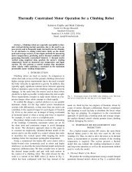
5referred to as sacrificial material, can be deposited as needed. During part machining,the mold serves as a custom fixture for the work piece. This provides geometricversatility unmet in conventional machining processes while providing the same dimensionalprecision <strong>and</strong> also accommodating s<strong>of</strong>t unmachinable materials that needto be molded. It is sometimes considered a layered manufacturing process but it isfundamentally different from previously mentioned rapid prototyping methods. Whilethe rapid prototyping methods build parts strictly in planar layers <strong>with</strong> even thickness,SDM-built layers generally vary in thickness <strong>and</strong> <strong>of</strong>ten intersect <strong>with</strong> each other.These properties specific to SDM allow the process to produce intricate functionalparts <strong>with</strong> complex geometry <strong>and</strong> material combination. The main drawback to thisprocess is its time-consuming serial process which is mainly attributed to materialdeposition.1.2 SDM specialtiesThe very nature <strong>of</strong> SDM as a hybrid <strong>fabrication</strong> method allows it to do things that areotherwise difficult or impossible. These include <strong>multimaterial</strong> part <strong>fabrication</strong> <strong>and</strong>component embedding. Such specialties have helped establish <strong>design</strong> <strong>of</strong> <strong>mechanisms</strong><strong>and</strong> systems that are distinctive to SDM.1.2.1 Multimaterial component <strong>fabrication</strong> via SDMOne <strong>of</strong> the properties that make SDM interesting is the repetitive material addition.Different materials can be deposited to compose monolithic <strong>multimaterial</strong> componentswhich are functionally much more versatile than single material hardware. One <strong>of</strong>the best proven applications <strong>of</strong> <strong>multimaterial</strong> SDM components is that in biomimeticrobot legs as seen in figure 1.2 (Clark et al., 2001a) (Cham et al., 2002). Compliant<strong>multimaterial</strong> monolithic legs consisting <strong>of</strong> rigid <strong>and</strong> s<strong>of</strong>t polyurethane are a simple<strong>and</strong> robust solution to realize desired kinematic, stiffness, <strong>and</strong> damping propertiesall in one. Consequently, <strong>mechanisms</strong> <strong>with</strong> custom <strong>design</strong>ed compliant joints, e.g.
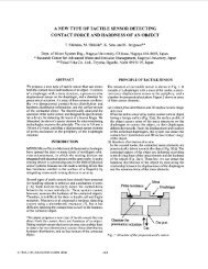
6Deposit (part)ShapeShapeDeposit (sacrificial)EmbedSupport SacrificialMaterialPart Part Embedded Embedded ComponentMaterial ComponentFigure 1.1: SDM process cycle involving material addition <strong>and</strong> removal <strong>and</strong> componentembedding
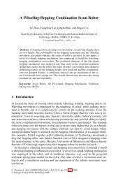
7Figure 1.2: SDM robot featuring embedded components <strong>and</strong> <strong>multimaterial</strong> legsflexures, have been identified as a specialty <strong>of</strong> SDM for its functional versatility supportedby relative ease <strong>of</strong> <strong>design</strong> <strong>and</strong> manufacture. Naturally, further exploration <strong>of</strong>SDM capabilities around compliant joints became an obvious area <strong>of</strong> challenge.1.2.2 Component embedding in SDMAnother SDM specialty is component embedding. When cavities are machined formaterial deposition, other things can also be placed inside. Since materials are addedin several discrete steps, unlike the usually uninterrupted addition in other rapidprototyping, the process interruption also provides a good opportunity for componentsto be inserted in the cavities. One application <strong>of</strong> component embedding is structuralstiffening or strengthening. Another is the embedding <strong>of</strong> functional components thatcannot or rather not be produced by SDM. These include mechanical componentslike joints <strong>and</strong> electric or electronic components ranging from circuitry, actuators, tosensors as seen in figures 1.2 <strong>and</strong> 1.3 (Cham et al., 1999) (Bailey et al., 2000) (Li et al.,2000) (Park, 2002)(Park et al., 2003). The research presented in this dissertation deals
8Figure 1.3: SDM leg <strong>with</strong> embedded components<strong>with</strong> both <strong>of</strong> the SDM specialty areas <strong>of</strong> compliant joints <strong>and</strong> component embedding.1.2.3 Other related works on SDMThere are several variations <strong>of</strong> SDM including those that use metals, polymers, <strong>and</strong>ceramics (Li et al., 1999) (Kietzman, 1998) (Cooper, 1999). Here, the discussion isprimarily on polymer SDM. Multimaterial part <strong>design</strong> for SDM has been studied theoretically<strong>and</strong> so is the manufacturing process planning (Rajagopalan <strong>and</strong> Cutkosky,1998) (Rajagopalan <strong>and</strong> Cutkosky, 1999) (Rajagopalan et al., 2000) (Binnard <strong>and</strong>Cutkosky, 1998) (Binnard, 1999) (Clark et al., 2001b). Discrete joints such as pinjoints have been both fabricated via SDM <strong>and</strong> embedded (Cham et al., 1999) (Parket al., 2003) (Stefanini et al., 2003). Compliant materials dynamics have been modeled<strong>and</strong> used in dynamic simulation to <strong>design</strong> <strong>and</strong> tune SDM fabricated robots (Xuet al., 2000) (Clark et al., 2004).1.3 MotivationApplication <strong>of</strong> SDM in mechatronic systems such as the previously mentioned robotshas created desires <strong>and</strong> needs to further develop its special capabilities. One is crossboundaryembedding <strong>of</strong> components which enables <strong>fabrication</strong> <strong>of</strong> integrated systems.Another is fiber reinforcement <strong>of</strong> flexures which overcomes some <strong>of</strong> the strength <strong>and</strong>
9stiffness limitations <strong>of</strong> flexures.1.3.1 Cross-boundary embeddingSDM applications in robots <strong>and</strong> other mechatronic systems have inspired desiresto embed components across material boundaries. Initial needs included exposure <strong>of</strong>electrical <strong>and</strong> pneumatic connectors <strong>and</strong> partial embedding <strong>of</strong> mechanical componentssuch as joints <strong>and</strong> springs(Cham et al., 1999). Newer needs include wiring across<strong>multimaterial</strong> compliant joints for electrical power supply <strong>and</strong> signal transfer, similarneeds in fluid systems for fluid channeling, <strong>and</strong> mechanical boundary crossing forstructural improvement.1.3.2 Flexure strength <strong>and</strong> stiffness modification by fiber reinforcementAs SDM robot <strong>design</strong>s were refined <strong>and</strong> simulation techniques were improved to determineflexure properties for better performance, <strong>design</strong> <strong>and</strong> <strong>fabrication</strong> technologyhad to keep up <strong>with</strong> the dem<strong>and</strong>. The challenge began <strong>with</strong> strength <strong>and</strong> flexibilitytrade<strong>of</strong>f when strength concerns arose as flexures were made thinner for increasedflexibility. There had also always been a dem<strong>and</strong> to increase a flexure’s stiffnessesfor secondary bending <strong>and</strong> twisting <strong>with</strong>out compromising the primary bending flexibility.More advanced needs were identified in having direction-dependent stiffnessspecifications, for example in a robot leg hip joint that can bend easier backward thanforward.1.4 ContributionsThe cross-boundary embedding work helps enable SDM <strong>fabrication</strong> <strong>of</strong> robust integratedmechanical systems. Fabrication process options were theoretically organized,explored <strong>and</strong> also experimented. The organized process options, along <strong>with</strong> someinitial application examples, provide the starting point for further exploration <strong>and</strong>refinement <strong>of</strong> cross-boundary embedding techniques.
10The flexure strength <strong>and</strong> stiffness modification work allows better realization<strong>of</strong> flexure <strong>design</strong> specifications <strong>with</strong>in dimensional constraints <strong>and</strong> limited materialchoice while maintaining <strong>design</strong> <strong>and</strong> <strong>fabrication</strong> simplicity. It also broadened the potentialapplication areas for flexures by overcoming their disadvantages. Furthermore,it provides a starting point for related applications such as flex sensor development<strong>and</strong> through-flexure wiring <strong>design</strong>.
Chapter 2Previous WorkIn order to prepare for cross-boundary embedding <strong>and</strong> fiber reinforcement <strong>of</strong> flexures,related works both in <strong>and</strong> outside SDM were studied. Component embedding workhas been demonstrated mainly in mass production <strong>and</strong> SDM. On the other h<strong>and</strong>,there are difficulties encountered in other rapid prototyping methods. Fiber reinforcementhas been long practiced by humans in various areas, mostly for structuralstrengthening. Some <strong>of</strong> the composite structures have also been modeled <strong>and</strong> studied.There have also been applications <strong>of</strong> anisotropic fiber stiffening for producing actuators.Finally, modeling <strong>and</strong> analysis methods for elastomer structures were studiedto aid the <strong>design</strong> <strong>of</strong> fiber-reinforced flexures.2.1 Previous work on component embedding2.1.1 Previous component embedding work: Non-SDMAlthough SDM is arguably the rapid prototyping process that most invites componentinsertion, due to its alternating additional <strong>and</strong> removal processes <strong>and</strong> comparativelysmall number <strong>of</strong> process layers, the problem <strong>of</strong> embedding components has also beenaddressed for other rapid prototyping processes. In discussing approaches for creatingprototypes containing discrete parts <strong>of</strong> a dissimilar material, it is useful to distinguish11
12between component insertion <strong>and</strong> component embedding. In the former case componentsare inserted into a cavity inside part material after the surrounding part is builtwhereas the immediate surrounding part material is cast after component placementin component embedding. Kataria et al. have developed methods for inserting componentsin stereo lithographed structures (Kataria <strong>and</strong> Rosen, 2000). DeLaurentiset al. have produced a robotic vehicle <strong>with</strong> inserted components also using stereolithography (Mavroidis et al., 2001) (DeLaurentis et al., 2002). These works mentionlimitations related to laser shadowing <strong>and</strong> obstruction <strong>of</strong> the material addition dueto the strictly planar layered nature <strong>of</strong> the <strong>fabrication</strong> method. This poses numerousconstraints on what can be inserted <strong>and</strong> when. Besides, the components are simplyinserted into a cavity that is left out during <strong>fabrication</strong>. Hence, there will be noadhesion <strong>of</strong> the encasing polymer to the inserted components unlike <strong>with</strong> embeddedcomponents in which polymer is cast <strong>and</strong> cured directly around them. For this reason,inserted components may have limited support from the encasing polymer comparedto embedded components.Component embedding has been implemented earlier in mass production. Insertmolding is common in large volume injection molding <strong>of</strong> thermoplastics <strong>and</strong> thermoplasticelastomers (Digiantonio, 1992) (Digiantonio, 2005). For example, many cableconnectors for electronic appliances have molded insulation housing over the metalconductors. An in-line skate wheel consists <strong>of</strong> inserted rigid core material <strong>and</strong> moldedhigher-friction tire material. (Please note the difference in the use <strong>of</strong> the word insertin this paragraph <strong>and</strong> the one before. Insertion in the previous paragraph refers tothat <strong>with</strong> respect to the polymeric part that is being produced. In this paragraph,it refers to the insertion <strong>of</strong> the component into the injection mold.) Since it is nota layered manufacturing, the part material can conform <strong>and</strong> bond to the insertedcomponent surface as it is injected into the mold. Two-shot molding <strong>of</strong> differentpolymers, as <strong>of</strong>ten seen in toothbrushes <strong>with</strong> hard <strong>and</strong> s<strong>of</strong>t material, is also a similarprocess. Large volume production also justifies greater time <strong>and</strong> monetary investmenton creating customized equipment for insert molding or two-shot molding. That isyet another factor that enabled the implementation <strong>of</strong> component embedding in massmanufacturing.
132.1.2 Previous component embedding work: SDMSDM’s high compatibility <strong>with</strong> component embedding has led to numerous implementationsup to date. Despite the fact that SDM is <strong>of</strong>ten categorized as layeredmanufacturing, it is notably different from other layered manufacturing methods.Ordinary layered manufacturing involves sequential stacking <strong>of</strong> fine strictly planargeometries which only grow in one direction. On the other h<strong>and</strong>, in SDM, materialcan also be added in levels lower than the top <strong>of</strong> the previously cast layer. The individuallayer thickness can also be much larger. These differences provide adequatephysical space <strong>and</strong> process planning freedom for component insertion. Furthermore,adding material immediately adjacent to inserted components is easy in SDM becausematerials are usually added in bulk <strong>and</strong> they naturally fill up any empty volume. Thisis <strong>of</strong>ten more challenging or even impossible for other layered manufacturing involvingselective material addition because <strong>of</strong> process obstruction. These properties <strong>of</strong>thicker <strong>and</strong> sometimes intersecting material layers added in bulk facilitate componentembedding in SDM. In effect, the process is much more like insert molding. (Itindeed is insert molding. The difference is that SDM is open molding whereas insertmolding is injection molding.) In addition, component insertion is also possible ifdesired. Examples <strong>of</strong> previous works are indicated in the previous chapter.2.2 Previous work in fiber-reinforced elastomers2.2.1 Application, modeling, <strong>and</strong> theoriesFiber reinforcement <strong>of</strong> materials has long been practiced in various fields. Wood is anaturally composite material. One <strong>of</strong> the very early human applications include reinforcement<strong>of</strong> earthen adobe <strong>with</strong> fibrous plant materials such as straw which datesback as far as 7000 B.C. (McHenry, 1988). More modern applications are in the fields<strong>of</strong> fiber-reinforced polymers as <strong>of</strong>ten seen in the aero-astro <strong>and</strong> racing industry forconstructing lightweight structures. Applications in fiber-reinforced elastomers includerubber tires <strong>and</strong> hydraulic tubings <strong>with</strong> embedded strengthening cords. (Wake
14<strong>and</strong> Wootton, 1982) covers the basics <strong>of</strong> textile-reinforcement <strong>of</strong> elastomers in practicalmanner. Tire properties have been studied actively since the 1960’s by manyinvestigators including (Clark, 1963b), (Clark, 1963a), (Clark, 1964), (Gough, 1968),(Akasaka, 1959), <strong>and</strong> (Biderman et al., 1963). Coated fabric properties have beenstudied by (Akasaka <strong>and</strong> Yoshida, 1972), (Alley <strong>and</strong> Fairslon, 1972), (Reinhardt,1976), (Skelton, 1971), <strong>and</strong> (Stubbs <strong>and</strong> Thomas, 1984). Chou et al. have modeled<strong>flexible</strong> composites that undergo large deformations. (Chou <strong>and</strong> Takahashi, 1987)Luo <strong>and</strong> Mitra et al., along <strong>with</strong> Chou, have studied <strong>flexible</strong> composites experimentally(Luo <strong>and</strong> Mitra, 1995) (Mitra <strong>and</strong> Luo, 1995) (Mitra <strong>and</strong> Luo, 1994a) (Mitra<strong>and</strong> Luo, 1994b) (Luo <strong>and</strong> Chou, 1990). Peel <strong>and</strong> Jensen et al. have also workedon the modeling <strong>flexible</strong> composites <strong>and</strong> developed <strong>fabrication</strong> methods (Peel et al.,1998) (Peel <strong>and</strong> Jensen, 2000). (Chou, 1992) is a good background reading for thefield <strong>of</strong> <strong>flexible</strong> composites.Please note the various terminologies used for referring to the general area <strong>of</strong>fiber or fabric reinforced elastomers. Flexible composites, coated fabrics, cord-rubbercomposites, <strong>and</strong> cord-reinforced rubber are some <strong>of</strong> the useful keywords for searchingfor literature about the subject.2.2.2 anisotropic property modification for kinematic functionalityGaylord invented <strong>and</strong> patented the McKibben actuator in 1958, which is a compositestructure <strong>of</strong> elastomer bladder contained <strong>with</strong>in braided fibers (Gaylord, 1958). Here,the two materials are separate from each other. Suzumori et al. have produced nearcylindricalsilicone rubber actuators <strong>with</strong> embedded fibers, circumferentially wrappedaround, that are pressure-activated to bend in different directions incorporating itsanisotropic material properties (Tanaka et al., 1991). Various mechanical systemssuch as walking robots, robotic h<strong>and</strong>s <strong>and</strong> grippers have been produced using thisactuator(Suzumori, 1996). However, the group has moved on to <strong>design</strong>ing similaractuators from a single material due to the difficulty <strong>of</strong> miniaturization <strong>of</strong> the compositestructure (Suzumori et al., 1996) (Takagi <strong>and</strong> Suzumori, 1996). Dohta et al.
15have produced a very similar <strong>flexible</strong> bending actuator, composed <strong>of</strong> silicone rubber,circumferentially wrapped reinforcement fibers, <strong>and</strong> a sheet <strong>of</strong> plastic also for reinforcement(Dohta et al., 2000). Tanaka et al. have also produced a similar actuator<strong>with</strong> fibers used in circumferential wrapping <strong>and</strong> longitudinal reinforcement (Tanaka,1993) (Tanaka et al., 1996). Here, the fibers are adhered to the rubber tube surface.2.3 Modeling <strong>and</strong> analysis for <strong>design</strong>In this thesis research, finite element analysis (FEA) was employed as the tool foranalyzing <strong>design</strong> options for fiber-reinforced flexures. Popular FEA s<strong>of</strong>tware for elastomersinclude ABAQUS, ANSYS, <strong>and</strong> MARC (ABAQUS, 2005) (ANSYS, 2005b)(MSCs<strong>of</strong>tware, 2005). The analysis involves the modeling <strong>of</strong> fibers <strong>and</strong> elastomeras analysis elements <strong>and</strong> integrating them into a single stiffness matrix. Fibers orstring elements can be effectively modeled as linear elements which only resist tensileload. On the other h<strong>and</strong>, elastomer modeling is rather delicate <strong>and</strong> complex. Mostresearch publications indicate that it is very difficult to simulate large deformation<strong>of</strong> elastomers (Lloyd-Lucas, 1999) (Ramsay, 1999) (Turner et al., 1999). Hyperelasticmaterial properties are commonly represented using the Mooney-Rivlin model or theOgden model (Rivlin <strong>and</strong> Saunders, 1951) (Adkins <strong>and</strong> Rivlin, 1952) (Adkins <strong>and</strong>Rivlin, 1955) (Ogden, 1982). These models are capable <strong>of</strong> h<strong>and</strong>ling large strains.For example, the Ogden model can h<strong>and</strong>le strains <strong>of</strong> up to 700% (ANSYS, 2005a).There are other hyperelastic material models such as Arruda-Boyce <strong>and</strong> Gent whichcan h<strong>and</strong>le strains <strong>of</strong> up to 300% <strong>and</strong> Neo-Hookean which is only applicable to smallstrains <strong>of</strong> up to 20 − 30% (Arruda <strong>and</strong> Boyce, 1993). Some others such as the polynomial<strong>and</strong> Yeoh models have varying strain level applicability depending on the number<strong>of</strong> parameters employed, just like the Mooney-Rivlin <strong>and</strong> Ogden models (Yeoh,1993). Both the Mooney-Rivlin <strong>and</strong> Ogden models require involved experimentationfor accurately determining the material properties that would lead to reliable analysisresults (Cadge <strong>and</strong> Prior, 1999) (Daley <strong>and</strong> Mays, 1999) (Gough et al., 1999)(Johannknecht et al., 1999). There have been efforts to simplify the material modelsbut these methods are still not mature enough (Shariff <strong>and</strong> Stalker, 1999) (Williams
16et al., 1999). On a side note, material testing is commercially available at costs fromaround $1500 for determining elastomer material properties(AxelProducts, 2000).FEA <strong>of</strong> structure <strong>with</strong> linear reinforcing elements was first demonstrated by (Ngo<strong>and</strong> Scordelis, 1967) for steel reinforced concrete. Coupling <strong>of</strong> fibers <strong>and</strong> elastomersin FEA was first demonstrated in tire simulation by (Watanabe <strong>and</strong> Kaldjian, 1983).Multiple cords were represented as one cord in the FEA model. The coincidentnodes <strong>of</strong> the elements were fixed <strong>with</strong> respect to each other to emulate the effect <strong>of</strong>interfacial bonding between the two. This approach <strong>of</strong> coupling coincident nodes wasdirectly applicable for the analysis <strong>of</strong> fiber-stiffened flexures dealt in this dissertation,even better than for the application in the original publication, because there wereonly finite number <strong>of</strong> fibers in the structure <strong>and</strong> each one <strong>of</strong> them could be includedin the model <strong>with</strong>out simplification by unification <strong>of</strong> multiple fibers. An alternativemethod exists for facilitating modeling <strong>of</strong> composite structures <strong>with</strong> arbitrary location<strong>and</strong> orientation <strong>of</strong> reinforcing elements. (Helnwein et al., 1993) However, the fiberorientations <strong>of</strong> interest were relatively small in variety for this dissertation researchsuch that the previously mentioned simpler method was adequate.Lists <strong>of</strong> literature on the finite element analysis <strong>and</strong> simulation <strong>of</strong> rubber <strong>and</strong>rubber-like materials are available in (Mackerle, 1998) <strong>and</strong> (Mackerle, 2004).2.4 Fibrous material selection for elastomer reinforcementThere are four major criteria for fiber material selection;• lengthwise stiffness,• flexibility in other directions,• strain resistance,• fatigue life,• strength,
17• bonding.The material is largely responsible for the stiffness while geometry also takessignificant role in the other properties. The finer the fibers are, the more <strong>flexible</strong> thebundle <strong>of</strong> fibers will be for equal total cross-sectional area because <strong>of</strong> slippage allowedbetween the fibers. This may also reduce maximum stress in fibers to improve strainresistance <strong>and</strong> fatigue life, especially in bending. Strength is also improved in abundle <strong>of</strong> finer fibers by inhibiting crack propagation. Bonding strength is closelyrelated to surface area, hence finer fibers also help improve this property. Polyester<strong>and</strong> cotton were the readily available materials that exhibited favorable properties.Cotton showed good bonding while moderate in stiffness <strong>and</strong> strength. Polyesterproved to be better at stiffness <strong>and</strong> strength but had limitations in bonding. As aresult, cotton or cotton/polyester blend were used. More information on this topic isavailable in (Wake <strong>and</strong> Wootton, 1982) (Gupta, 1998) (Gupta, 2001).
Chapter 3Cross-boundary embedding <strong>of</strong><strong>flexible</strong> componentsAs mentioned in Chapter 1 <strong>and</strong> 2, an important advantage <strong>of</strong> SDM <strong>with</strong> respectto other rapid prototyping processes is that it is relatively easy to embed components.In comparison <strong>with</strong> commercial layered manufacturing processes such as fuseddeposition modeling <strong>and</strong> stereo-lithography, SDM has a relatively small number <strong>of</strong>cycles, which generally correspond to transitions between upward- <strong>and</strong> downwardfacing part surfaces (<strong>with</strong> respect to the growth direction) or to changes in the partmaterial. The breaks between cycles create a natural point at which discrete partscan be added. Many examples <strong>of</strong> multi-material parts, including parts <strong>with</strong> embeddedcomponents, have been created <strong>and</strong> the process planning for such parts has beendescribed in previous work (Cham et al., 1999) (Binnard, 1999). However, a number<strong>of</strong> unsolved problems remain. Foremost among these are the problems associated<strong>with</strong> embedding components that traverse material boundaries, especially when embedding<strong>flexible</strong> components. The treatment <strong>of</strong> <strong>flexible</strong> elements that cross materialboundaries in SDM is covered in this chapter.18
193.1 IntroductionThere are several common reasons for embedding <strong>flexible</strong> elements in multi-materialparts. One common application <strong>of</strong> fibers is to alter the strength or stiffness <strong>of</strong> a part.Fiber-reinforced materials are common both in nature <strong>and</strong> in man-made productsranging from golf clubs to fiberglass boats to automobile tires. In these examples,fibers are used that have a considerably higher specific strength or stiffness thanthe surrounding material. In other applications, <strong>flexible</strong> elements such as wires orfiber optic str<strong>and</strong>s may be embedded to transmit power <strong>and</strong>/or signal through thepart. Similarly, hydraulic <strong>and</strong> pneumatic tubes may be embedded <strong>with</strong>in a part.In each <strong>of</strong> these applications, it may be desired to have the fibers, tubes or wirescontinue uninterrupted across transitions from one material region to another. Thiswould enable the production <strong>of</strong> a functionally integrated joint which can transfernot only force <strong>and</strong> displacement but also information, energy, <strong>and</strong> material. Thework described in this chapter has led to four basic methods to accommodate suchcross-boundary <strong>flexible</strong> embedded elements. In addition, two alterative methods aredescribed that essentially emulate the functionality <strong>of</strong> cross-boundary embedding.The challenges associated <strong>with</strong> cross-boundary embedding are primarily:• Precisely defining the location <strong>and</strong> orientation <strong>of</strong> the embedded componentduring the <strong>fabrication</strong> process.• Selectively adding, removing, or otherwise processing material around the embeddedcomponents <strong>with</strong>out damaging them or being hindered by them.• Preventing stress concentrations at material boundaries that could lead to earlyfailure.In the following section these issues are discussed in the context <strong>of</strong> a simple abstractexample <strong>of</strong> an embedded <strong>flexible</strong> component that straddles the boundary betweentwo different part materials as shown in Figure 3.1. The requirements for thefinished product are as listed below. The criteria consist <strong>of</strong> geometric requirements,interfacial bonding requirements, <strong>and</strong> functional requirements.
20Material BFlexible componentMaterial AFigure 3.1: Crossboundary embedding objective1. Embedded component crosses the material boundary.2. Location <strong>and</strong> shape <strong>of</strong> the embedded component are precisely defined.3. Inter-material boundary geometry is precisely defined.4. Individual part material geometry is precisely defined.5. Secure material bonding is established at all interfaces; between the embeddedcomponent <strong>and</strong> the part materials <strong>and</strong> between the two part materials.6. The embedded component is functional, i.e. it meets functional requirementsfor strength <strong>and</strong> stiffness <strong>and</strong> fatigue life <strong>and</strong> maintains any additional functionalitiessuch as the ability to transfer signal, energy, or material.7. The encasing part materials are functional, i.e. their functionality is not compromisedby the addition <strong>of</strong> the <strong>flexible</strong> component or by the processes used tocreate the part.3.2 Fabrication method <strong>and</strong> nomenclatureThe <strong>fabrication</strong> method <strong>and</strong> nomenclature are explained in this section as basic backgroundinformation for the underst<strong>and</strong>ing <strong>of</strong> the work.
213.2.1 Materials <strong>and</strong> manufacturing methodsIn Shape Deposition Manufacturing (SDM), various materials can be deposited, <strong>and</strong>also removed, to obtain the desired part. When materials are selected prioritizingtheir functionality in the finished product, they may not necessarily have desirableproperties for <strong>fabrication</strong>. In order to overcome limitations in <strong>fabrication</strong> due to materialselection, temporary materials that are better suited for <strong>fabrication</strong> are sometimesincorporated into the process to facilitate production. These materials, called sacrificialmaterials, only serve to facilitate the production <strong>and</strong> they do not remain in thefinished product. On the other h<strong>and</strong>, the materials that remain in the finished productto help realize its functionality are referred to as part materials. In the examplesthat follow, combinations <strong>of</strong> stiff polymers <strong>and</strong> <strong>flexible</strong> elastomers are employed forcreating the parts, <strong>and</strong> waxes or uncured polymers as the sacrificial support materials.Flexible components included fibers, fabrics, electrical wires <strong>and</strong> <strong>flexible</strong> printedcircuits. CNC machining <strong>and</strong> a hot water jet were employed for selective removal <strong>of</strong>sacrificial materials; solvents were employed for bulk removal.3.2.2 NomenclatureIn the following discussions <strong>and</strong> examples, a series <strong>of</strong> schematic diagrams are used formanufacturing process illustration. The diagrams are all overhead views <strong>of</strong> a part inprocess. In other words, machining tool access <strong>and</strong> material deposition both occurin the orientation normal to the plane <strong>of</strong> the page. Figure 3.2 is a diagram for colorscheme explanation.For generality we further assume that one <strong>of</strong> the part materials, B, is possibly as<strong>of</strong>t material for which controlled material addition or removal is impractical. Thus,material B can only be added or removed in bulk.Glossary <strong>of</strong> components <strong>and</strong> materials:• Flexible component: A highly deformable part that improves properties <strong>of</strong> oradds functionality to the product. It may contribute to structural improvements(e.g. strengthening or stiffening) <strong>and</strong>/or energy, motion, material, <strong>and</strong>/or signal
22Material BMaterial ACavityDepositedSacrificialFlexiblecomponentSacrificialFigure 3.2: Generic in-process example <strong>with</strong> embedded <strong>flexible</strong> fiberstransfer. Typical examples include fibers, fabric, electric wire, <strong>and</strong> pneumatictubing.• Part material: Deposited material that constitutes the final product. Part materialsare selected prioritizing their properties in the final form rather than their<strong>fabrication</strong> properties. Typical part materials include polymers <strong>and</strong> elastomerssuch as polyurethane, epoxy, <strong>and</strong> silicone <strong>with</strong> varying material properties. Inthe examples employed in this chapter, materials A <strong>and</strong> B are part materials.Of these two materials, material A is assumed to be a stiff polymer that ismachinable <strong>and</strong> material B is a <strong>flexible</strong> elastomer that cannot be machined.• Sacrificial material: Temporary materials used to aide <strong>fabrication</strong>. Part materialsmay have properties that are not ideal for <strong>fabrication</strong> since they arechosen based on their functionality in the finished product. Sacrificial materialsthat do not remain in the finished product are selected based on their propertiesthat facilitate <strong>fabrication</strong>. These include the ability to be (1) deposited incontrolled geometry, (2) removed in controlled geometry, (3) easily deposited<strong>with</strong>out damaging the <strong>flexible</strong> component or part materials, <strong>and</strong> (4) easily <strong>and</strong>cleanly removed when no longer needed. Typical sacrificial materials includewaxes <strong>with</strong> various melting temperatures <strong>and</strong> stiffnesses as well as solid soap.
233.3 Partial <strong>and</strong> cross-boundary embedding challengesAs previously mentioned, the three main difficulties associated <strong>with</strong> creating parts<strong>with</strong> embedded <strong>flexible</strong> components were fixturing the <strong>flexible</strong> members, achievinggood control <strong>of</strong> the geometry <strong>of</strong> part materials in the vicinity <strong>of</strong> the <strong>flexible</strong> elements,<strong>and</strong> avoiding stress concentrations. These difficulties are explained in the remainder<strong>of</strong> this section.3.3.1 Fixturing challenges for <strong>flexible</strong> componentsComponents need to be properly located inside the mold upon embedding. Sometimes,parts are directly placed inside an empty mold. Component location can bedefined using matching features on the mold. At other times, components are placedin a partially filled cavity. The bottom <strong>of</strong> the cavity would already be filled <strong>with</strong>part material <strong>with</strong> machined features that matched the component to be embedded.Another method is to fabricate a custom harnessing fixture for the component to useas a support when placing it inside a mold, either empty or partially filled. In all<strong>of</strong> the above cases, the component can obtain additional fixturing support by usingadhesives <strong>of</strong>ten in the form <strong>of</strong>, but not limited to, fluids. These methods are generallyeffective for rigid components. However, <strong>flexible</strong> components such as electrical wiresor reinforcement fibers <strong>and</strong> fabrics <strong>of</strong>ten require other means <strong>of</strong> fixturing to achievedesired locating accuracy. In addition, <strong>flexible</strong> components, which cannot supporttheir own shapes require some means for defining the shape. Several alternate methodshave been developed.3.3.2 Material deposition <strong>and</strong> removal challengesTo satisfy the previously defined requirements, any combination <strong>of</strong> controlled materialdeposition <strong>and</strong> removal may be used. For example, in the case <strong>of</strong> fused depositionmodeling (FDM) the part materials are deployed precisely to the desired shape; inthe case <strong>of</strong> shape deposition manufacturing (SDM) controlled material removal or
24shaping is used to create the desired shape. These processes will be referred to asselective material addition <strong>and</strong> removal, respectively, in the following discussion. Thechallenge in each case is (1) not to be hindered by the <strong>flexible</strong> material (i.e. to haveaccess to all regions desired) <strong>and</strong> (2) to avoid damaging the <strong>flexible</strong> elements as aside-effect <strong>of</strong> the material deposition, removal or curing process.A typical problem is to prevent castable materials (i.e., bulk material addition)from infiltrating regions where they are not desired. When <strong>flexible</strong> fibers pass throughthe boundary <strong>of</strong> a region, sealing can be especially difficult. On the other h<strong>and</strong>,removing material around a <strong>flexible</strong> component can lead to problems because the<strong>flexible</strong> element is unable to support itself as it becomes released <strong>and</strong> this may hinderprecise material removal or increase the risk <strong>of</strong> component damage.Where selective material addition or removal is impractical in the vicinity <strong>of</strong> <strong>flexible</strong>elements, the alternatives are bulk material addition or removal. For example,these include casting a liquid polymer into a cavity or removing an entire region <strong>of</strong>sacrificial material by melting it or washing it away <strong>with</strong> solvent. A variation on thisprocess is to combine SDM <strong>with</strong> photolithography in which a mask <strong>and</strong> UV light areused to define a geometric pattern, followed by bulk material removal <strong>with</strong> solvent.Examples <strong>of</strong> these methods are presented in the next section. However, in this casethere is the problem that the fibers may shield or shadow the material underneath.Similar interference problems have been identified by other researchers (Kataria <strong>and</strong>Rosen, 2000) (DeLaurentis et al., 2002).Glossary <strong>of</strong> processes:• Selective deposition: Controlled material addition such that the material isdeposited only to <strong>design</strong>ated locations to form a defined geometry. Fused depositionmanufacturing (FDM) is an example <strong>of</strong> selective deposition.• Bulk deposition: Uncontrolled material addition such that the material is freeto fill all available volume. Molding is an example <strong>of</strong> bulk deposition.• Selective removal: Controlled material removal such that the material is removedonly from <strong>design</strong>ated locations to leave behind a defined geometry. Machiningis an example <strong>of</strong> selective removal.
25• Bulk removal: Uncontrolled material removal such that all <strong>of</strong> the material <strong>of</strong>the same kind will be removed. Chemical etching <strong>and</strong> melting are examples <strong>of</strong>bulk removal.3.3.3 Stress concentration considerationsStress concentration is one <strong>of</strong> the most important factors to be considered when<strong>design</strong>ing structures that deform or bear cyclic loads. A stiff material may crack; as<strong>of</strong>t material may tear; delamination may occur at a material interface. An embeddedcomponent may also break when the surrounding matrix deforms.Sharp-edged concave geometries are generally undesirable, both on the exterior<strong>of</strong> the part <strong>and</strong> on interior boundaries between dissimilar materials. Stress concentrationsalso occur where there is an abrupt change in the Young’s moduli. Theobvious countermeasure is to avoid having material boundaries at locations wherehigh stresses are expected. In a smaller scale, inter-material bonding strength canalso be strengthened by selecting materials or material combinations <strong>with</strong> appropriatechemical properties <strong>and</strong> by adding geometric interlocking features or simply byincreasing the interfacial surface area. In addition, microscopic defects on materialsurfaces - especially for s<strong>of</strong>t materials that undergo large strains - should be avoided.For example, it is known that selective material removal for s<strong>of</strong>t materials will leadto surface cracks <strong>and</strong> poor fatigue life (Kietzman, 1998). However, by modifying theprocess plan, the s<strong>of</strong>t material (generic material B) can be cast into a smooth cavitythat establishes its shape, hence eliminating the need for material removal. Examples<strong>of</strong> linkages <strong>with</strong> flexures that have survived over 1 million cycles are presented in thenext section.3.4 SolutionsSolutions for the fixturing problem are mentioned followed by solutions for the generalprocess planning. The process planning solutions include both real cross-boundary
26embedding solutions <strong>and</strong> alternative solutions that can provide similar effects. Selectionguidelines for the various methods are also provided.3.4.1 Flexible component fixturing solutionsTwo new methods have been developed for fixturing <strong>flexible</strong> components. Here, theobjective was to locate <strong>flexible</strong> components <strong>with</strong> high accuracy in a defined shape forembedding in cast material. The <strong>flexible</strong> components are generally not stiff enoughto hold themselves in proper position when they are left <strong>with</strong>out support. Hence,previous methods <strong>of</strong> direct placement inside empty or partially filled mold cavitiesare not applicable. Another problem, which is also encountered in direct placement<strong>of</strong> <strong>flexible</strong> components, is displacement by floating. Light <strong>flexible</strong> components suchas threads <strong>and</strong> fabrics may easily float out <strong>of</strong> the mold cavity, especially duringthe degassing process for air bubble removal immediately after the material castingbecause <strong>of</strong> the vigorous bubbling. Generally, it would also not be appropriate touse a permanent rigid harness for supporting the component since it would hinderthe flexibility <strong>of</strong> the component <strong>and</strong> the finished product. In some initial attempts,fluid adhesives were used to temporarily fixture reinforcing fabric to the bottom <strong>of</strong> themold. Relatively thick cyanoacrylate adhesive was employed so as to localize adhesiveinfiltration in the fabric which would lead to its stiffening. This is a simple <strong>and</strong> validmethod when the positioning accuracy requirement is not very tight <strong>and</strong> the fabricdoes not need to be in tension. However, it is a rather unreliable skill-dependentmethod <strong>and</strong> hence performance consistency cannot be expected. The two methodsto follow are intended to overcome these problems <strong>and</strong> limitations.Pre-encapsulationOne method is to pre-encapsulate (pre-embed) the <strong>flexible</strong> component in a polymer.It is a preparatory procedure for the <strong>flexible</strong> component which is otherwise unfit forcross-boundary embedding processes. By having a layer <strong>of</strong> another material encasingit, it can have sufficient rigidity for keeping its shape <strong>and</strong> also enough density toprevent displacement by flotation. Even then, some sort <strong>of</strong> fixation is still required
27for the pre-encapsulation process. However, the advantage in performing the preencapsulation<strong>of</strong>f-line as opposed to direct in-situ embedding is that more elaboratefixtures can be used because <strong>of</strong> less spatial limitations during the process <strong>and</strong> alsobecause the fixture can be removed from the component before its incorporation intothe mechanism in production.The best way to define the geometry <strong>of</strong> a <strong>flexible</strong> component is to apply tension.Naturally, straight forms are the simplest to produce when tension is used. For example,fiber-reinforced elastomer strips can be produced by holding fibers in tensionin a shallow mold cavity supported by anchors at both ends <strong>and</strong> then casting thematerial into the mold. The process is shown schematically in figure 3.3. Moldingprovides a significantly better dimensional accuracy compared to polymer impregnationin open space or vacuum bagging, <strong>and</strong> this is helpful in the component h<strong>and</strong>lingwhen integrating it to the final mechanism. The increased size, rigidity, <strong>and</strong> betterdefined geometry would also make the component easier to fixture.Curved geometries can also be produced in a similar fashion by running fibersin tension in a curved cavity <strong>and</strong> relying on the cavity inner walls for the curves.Another way to fixture fibers in a curved geometry is to first prepare a straightstrip as previously mentioned <strong>and</strong> to fixture it in curved geometry in later stages <strong>of</strong><strong>fabrication</strong>. When the pre-encapsulated component is to be re-embedded as in thiscase, rib-like features either on the <strong>flexible</strong> material or the rigid surrounding are usefulfor positioning <strong>and</strong> supporting. The ribs behave like the custom harnesses used forrigid component embedding. One can also pre-embed a <strong>flexible</strong> component <strong>with</strong>outfixture by using a tightly made mold that will fit the component inside <strong>with</strong> sufficientlocating accuracy.The surrounding material can also serve as a protective layer for preventing undesiredmaterial infiltration or chemical reactions that influence functionality or bondingproperties. Examples <strong>of</strong> these applications will be discussed later along <strong>with</strong> detaileddescription <strong>of</strong> the process options. The extra layer can also be a bonding agent interlinkingthe <strong>flexible</strong> component <strong>and</strong> the surrounding part material if the two cannotbond well directly. In short, the benefits <strong>of</strong> pre-encapsulation extend beyond solvingfixturing problems.
28Anchor pinsString alignment nutPrepare mold <strong>and</strong> insert fixtures. Here,string alignment nuts <strong>and</strong> anchor pinsare used on both sides.StringsSet string in tension. Typically, longerflexural elements are made <strong>and</strong> cutinto appropriate sizes. However, stringstend to float in the uncured polymer<strong>and</strong> be misplaced when they are too long.Fill mold <strong>with</strong> polymer. Extract theresulting product from mold. Removethe end fixtures. Cut the product intodesired lengths <strong>and</strong> use in other products.Figure 3.3: Pre-encapsulation process example illustration
29Suspending fixture methodAnother method is to create a custom harness for the <strong>flexible</strong> component <strong>and</strong> suspendit into the mold cavity. The process cartoon is shown in figure 3.4. The harness wouldtypically secure the <strong>flexible</strong> component in two or more locations. These multiplesecuring parts would be in one rigid piece until the component is fully embedded.And then they would be separated, for example by machining the top part <strong>of</strong>f, toallow relative motion <strong>of</strong> the pieces. Initially, the securing parts are held together t<strong>of</strong>acilitate preparation <strong>of</strong> the geometry. For example, preparing fabrics or fibers to beembedded in tension is much easier when the securing anchor pieces are fixed <strong>with</strong>respect to each other instead <strong>of</strong> being free. In addition, positioning one structure ina mold is much simpler <strong>and</strong> <strong>of</strong>ten reliable than having to position multiple securingpieces. An example <strong>of</strong> this method is shown in the following chapter.The first method <strong>of</strong> pre-encapsulation is useful for relatively simple geometries <strong>and</strong>it can be applied in small sizes as well. The second method <strong>of</strong> fixture suspension isable to achieve more complex geometries, but fixture <strong>design</strong> <strong>and</strong> preparation may betroublesome. The first method would generally be recommended whenever possible,especially for large volume manufacturing, because <strong>of</strong> the complexity involved inperforming the second method.3.4.2 Material deposition <strong>and</strong> removal solutionsThis section describes several process options for creating multi-material parts <strong>with</strong>embedded <strong>flexible</strong> components that overcome difficulties described in the previoussection. The options are illustrated <strong>with</strong> examples <strong>of</strong> <strong>mechanisms</strong> actually created<strong>and</strong> their accompanying process plans.The process options consist <strong>of</strong> combinations <strong>of</strong> material deposition <strong>and</strong> removal,both <strong>of</strong> which can be either selective (=controlled) or bulk (=uncontrolled). Selectivematerial deposition is the process <strong>of</strong> depositing material specifically at <strong>design</strong>atedlocations. Fused deposition manufacturing is an example <strong>of</strong> selective material deposition.Bulk material deposition, on the other h<strong>and</strong>, allows the material to fill anyempty volume <strong>with</strong>out geometric control <strong>and</strong> it is exemplified by molding processes.
30Machine cavities for flexure <strong>and</strong>for anchor alignment pinsalignment pinssupport blockstringsInsert anchor assemblyanchor blocksFill cavity <strong>with</strong> s<strong>of</strong>t materialShave <strong>of</strong>f unnecessary support structureExtract piece from moldFigure 3.4: Suspending fixture method
31Selective material removal takes material away specifically from <strong>design</strong>ated locations.Machining is an example <strong>of</strong> selective material removal. In contrast, bulk material removaltakes away all materials for which the process is applicable <strong>with</strong>out geometriccontrol. Chemical etching <strong>and</strong> melting by heat are examples <strong>of</strong> bulk material removal.Each <strong>of</strong> the process options involves one step <strong>of</strong> selective material addition orselective material removal. The various process sequences are illustrated schematicallyin Figure 3.5 <strong>and</strong> are understood to represent partial process plans or plan fragments.In each case, it is assumed that the process starts <strong>with</strong> creating temporary or sacrificialfixtures <strong>and</strong> inserting the <strong>flexible</strong> material into them. In the documentation to follow,processes are named after the selective process employed.Selective material depositionThe most straightforward approach to achieving the configuration in Figure 3.1 is toselectively deposit either material A or material B so as to create a defined boundarybetween them while encapsulating the <strong>flexible</strong> component. This approach is labeledas sequence I in Figure 3.5 <strong>and</strong> the manufacturing steps are depicted in Figure 3.6.Let us go through the process step by step following Figure 3.6. (1) The molddefines the outer geometry <strong>of</strong> the product. The fixtures define the location <strong>and</strong> shape<strong>of</strong> the embedded <strong>flexible</strong> component. They have to remain there until the <strong>flexible</strong>component is securely embedded. (2) The <strong>flexible</strong> component is held in place by thefixtures. The fixture must be able to hold the <strong>flexible</strong> component securely. Securingoptions include press fit, tying, bolt fastening, <strong>and</strong> adhesive application among others.When the component’s limited size, strength or stiffness inhibits secure fixturing,it can be pre-encapsulated in a material that can improve these properties <strong>with</strong>outhindering the functionality. Depending on the fixture <strong>design</strong>, it may be more appropriateto set the <strong>flexible</strong> component in the fixturing structure before inserting themin the mold. (I-3) Material A is selectively deposited into its <strong>design</strong>ated location.This process defines the inter-material boundary geometry <strong>and</strong> is also responsible forestablishing material bonding <strong>with</strong> the <strong>flexible</strong> component. Selective material depositionlike FDM <strong>and</strong> stereo lithography usually require access in the proximity <strong>of</strong> thedeposition location, physical or optical, <strong>and</strong> that can result in interference problems
32(1) Create mold <strong>and</strong> fixture(2) Place <strong>flexible</strong> component(I)(II)(III)(IV)(I-3) Selectively depositpart material A(II-3) Bulk depositpart material A(III-3) Selectively depositsacrificial material(IV-3) Bulk depositsacrificial material(I-4) Bulk depositpart material B(II-4) Selectively removepart material A(III-4) Bulk depositpart material A(IV-4) Selectively removesacrificial material(II-5) Bulk depositpart material B(III-5) Bulk removesacrificial material(IV-5) Bulk depositpart material A(III-6) Bulk depositpart material B(IV-6) Bulk removesacrificial material(IV-7) Bulk depositpart material BRemove fixtureFill fixture cavitiesExtract from moldFigure 3.5: Process chart for the four main methods for partial <strong>and</strong> cross-boundaryembedding: (I) selective material deposition, (II) selective material removal, (III)selective deposition <strong>of</strong> sacrificial material, (IV) selective removal <strong>of</strong> sacrificial material.
3412I-3I-4Create mold <strong>and</strong> fixturePlace <strong>flexible</strong> componentSelectively deposit part material ABulk deposit part material BFinishReleaseFigure 3.6: Selective material deposition (Process I, Fig.3.5 ) for creating a twomaterialpart <strong>with</strong> embedded <strong>flexible</strong> elements.
35III-3III-4III-5Selectively deposit sacrificialmaterialBulk deposit part material ABulk remove sacrificial material.Proceed to bulk deposition <strong>of</strong> B.Figure 3.7: Selective sacrificial material deposition (Process III, Fig. 3.5)remaining on the <strong>flexible</strong> component which might degrade the bonding properties orthe component functionality. This is especially challenging for fibrous componentswhich wick the sacrificial material, <strong>and</strong> a valid solution is, again, to pre-encapsulatethe component before depositing the sacrificial material. The removal process canusually be a bulk removal process that takes away all <strong>of</strong> the selectively deposited sacrificialmaterial by geometrically uncontrolled means such as melting <strong>and</strong> dissolving.However, the fixture must either remain or be replaceable to locate <strong>and</strong> shape theliberated portion <strong>of</strong> the <strong>flexible</strong> component. The bulk removal process is <strong>of</strong>ten facilitatedby temporarily extracting the entire part from the base mold. However, oneneeds a reliable means <strong>of</strong> placing the part back into a mold <strong>with</strong> reliable positioningaccuracy.A technique that can be used to enhance the control <strong>with</strong> which either part orsacrificial material is added, is to temporarily create narrow shapes such as channelsso that added material is kept in place by capillary action while still in the liquidstate. This is the approach used for the string-suspended gimbals as shown in Figure3.8<strong>and</strong> Figure 3.9. The <strong>flexible</strong> fibers in this case are φ1.0[mm] diameter strings<strong>of</strong> cotton yarn. A mold is first created in sacrificial material (wax) <strong>and</strong> the fibersare stretched <strong>and</strong> held in place. Small amounts <strong>of</strong> additional sacrificial material are
37Figure 3.9: Finished mechanism <strong>with</strong> string-suspended gimbals supporting upper <strong>and</strong>lower plates.part material is illustrated as process II in Figure 3.5. When working <strong>with</strong> embedded<strong>flexible</strong> components, however, selective removal <strong>of</strong> sacrificial material was morecommonly employed (process IV in Figure 3.5, modified steps in Figure 3.10.) tocreate a shaped cavity into which part material can be introduced by bulk deposition<strong>with</strong>out damaging <strong>flexible</strong> materials. The required considerations for the twoprocesses are very similar. When the first material is added in bulk in step (II-3)or (IV-3), the material must be chosen such that they can be cleanly removed bythe selective removal process to follow so that neither the bonding properties or thefunctionality are influenced. Again, a fibrous component would be challenging <strong>and</strong>pre-encapsulation is a good solution to overcome the problem. In figure 3.10, process(IV-4) is separated into two parts. The first step represents a rough selective removalprocess which may be fast but have the risk <strong>of</strong> damaging the inserted component.The second step represents a possibly slower but also gentler removal process for thesafety <strong>of</strong> the <strong>flexible</strong> component. An example would be the combination <strong>of</strong> machining<strong>and</strong> focused hot water jet used to remove wax.Selective removal <strong>of</strong> sacrificial material was employed in building the spring-loadedflexural hinge shown in Figure 3.11. The <strong>flexible</strong> insert in this example is a coil spring
38IV-3IV-4IV-5Bulk deposit sacrificialmaterialSelectively remove sacrificialmaterial (rough)Selectively remove sacrificialmaterial (fine)Bulk deposit part material A.Proceed to bulk removal <strong>of</strong>sacrificial <strong>and</strong> bulk deposit B.Figure 3.10: Selective sacrificial material removal (Process IV, Fig. 3.5) : initialselective removal <strong>with</strong> a conventional process such as CNC machining provides asmooth surface finish over most <strong>of</strong> the interface region; residual sacrificial material onthe <strong>flexible</strong> elements is removed <strong>with</strong> a hot water jet or other process that does notaffect fibers.
39that is anchored in solid polymer at each end. The spring was first completely encasedin sacrificial wax <strong>and</strong> then its ends were exposed by selectively removing wax. Theremaining wax in the center protected the spring when solid polymer (material A)was cast around it. The completed product is shown in Figure 3.12.PhotolithographyFor delicate fibers, it may be difficult to remove sacrificial materials selectively <strong>with</strong>outcausing damage. A useful variation in such cases is to employ a photosensitivematerial that is selectively exposed <strong>and</strong> then removed chemically. This method wasused to create another flexural hinge <strong>with</strong> embedded fibers <strong>and</strong> fine electrical wires,following the process shown in Figure 3.13. This is a variation <strong>of</strong> the selective removal<strong>of</strong> part material in which the selective removal process is decomposed into two steps<strong>of</strong> (1) a non-physical photo-chemical selective material property change <strong>and</strong> (2) bulkremoval <strong>of</strong> the photo-chemically unaltered material.A photo-curable epoxy, SU-8 was employed as the rigid part material. Bundles <strong>of</strong>threads <strong>and</strong> wires were placed in a sacrificial mold, encapsulated in SU-8 <strong>and</strong> bakedat low temperature to drive <strong>of</strong>f the solvents, following the st<strong>and</strong>ard procedure forthick layers <strong>of</strong> SU-8 (SU-8, 2001). A mask was then positioned to block UV lightfrom the region <strong>of</strong> the flexure. The sample was exposed to UV light <strong>and</strong> a solventwas applied to remove the unexposed SU-8. A s<strong>of</strong>t solicone was then cast into theflexure region. After curing, the part was released from the sacrificial mold. An earlyfinished prototype is shown in Figure 3.14. Subsequent steps for a part using thisapproach would be to machine the upper surface <strong>of</strong> the hard SU-8 material <strong>and</strong> thencontinue <strong>with</strong> additional SDM cycles to create more featuresSummary <strong>of</strong> <strong>design</strong> <strong>and</strong> material selection guidelinesThe <strong>design</strong> <strong>and</strong> material selection guidelines for the four major methods <strong>of</strong> crossboundaryembedding are summarized in table 3.1.
40Machine mold in support material <strong>and</strong> place coil spring inside . Then bulkdepositwax to protect the spring from being embedded in plastic.Release the wax-encased spring from the mold <strong>and</strong> selectively remove wax from itsends to expose sections to be embedded in plastic. Replace in new mold.Bulk-deposit part material A in mold cavity <strong>and</strong> machine mold cavity for theflexure in the part material <strong>and</strong> mold. Insert reinforcement fabric in slot.Bulk-deposit s<strong>of</strong>t material B to encapsulate fabric. Extract part from mold <strong>and</strong>bulk-remove protective wax from coil spring by melting.Figure 3.11: Process steps for creating a durable spring-loaded hinge <strong>with</strong> a combination<strong>of</strong> hard <strong>and</strong> s<strong>of</strong>t polymers <strong>and</strong> a fabric-reinforced flexure
41Figure 3.12: Photograph <strong>of</strong> the finished spring-loaded hinge <strong>with</strong> fabric-reinforcedflexureSelective DepositionDesign: Create geometry to provide clear access for deposition tool. Create moldfeatures to facilitate control <strong>of</strong> material (e.g. by capillary action).Material: Use mold/part material combination <strong>with</strong> good wetting in corners <strong>and</strong>narrow passages. Deposit material <strong>with</strong> moderate viscosity <strong>and</strong> fast solidification tominimize reflow.Selective RemovalDesign: Create geometry to provide clear access for removal tool. Provide space <strong>and</strong>routes for waste material removal.Material: Use mold/part material combination <strong>with</strong> large difference in meltingtemperature or resistance to chemical, solvent or abrasive removal.Table 3.1: Design <strong>and</strong> material guidelines for cross boundary embedding
42Machine mold in support material <strong>and</strong> place <strong>flexible</strong> insert.Bulk add photocurable polymer (SU-8)Position photomask over flexure region <strong>and</strong> expose in collimated UV light.Bake <strong>and</strong> use solvent to remove the unexposed polymer.Bulk-add <strong>flexible</strong> polymer (material B)<strong>and</strong> extract component from support material.Figure 3.13: Process steps for creating a fiber-reinforced flexure <strong>with</strong> hard (SU-8) <strong>and</strong>s<strong>of</strong>t (silicone) materials.
43SU-8 (photocurable polymer)Embedded electrical wireS<strong>of</strong>t Silicone20mmFigure 3.14: Finished flexure fabricated from SU-8 <strong>and</strong> <strong>flexible</strong> silicone. (Source: S.Bailey, Stanford CDR)
443.4.3 Alternative solutionsThe alternative solutions are methods that emulate the effects <strong>of</strong> cross-boundaryembedding <strong>with</strong>out actually doing so. The solutions help overcome manufacturingconstraints that unable the implementation <strong>of</strong> the four methods previously discussed.They can also simplify the <strong>fabrication</strong> process by reducing the number <strong>of</strong> steps <strong>and</strong>by eliminating high-risk processes. There are two methods; pre-encapsulation <strong>and</strong>pseudo-boundary formation.Pre-encapsulationWe have already seen pre-encapsulation mentioned as a solution for various problemsidentified above <strong>and</strong> in fixturing. Just to refresh your memory, it is a preparatoryprocedure so that a <strong>flexible</strong> component incapable <strong>of</strong> direct exposure to the crossboundaryembedding methods can go through the processes. The main purposes<strong>of</strong> pre-encapsulation are (1) to add sufficient rigidity, size, strength, density, <strong>and</strong>or geometric definition to the <strong>flexible</strong> component to enable secure fixturing, (2) topre-infiltrate fibrous materials to prevent unwanted part or sacrificial material infiltrationthat would degrade its bonding or functional properties, <strong>and</strong> (3) to coat<strong>and</strong> treat material surface to improve bonding. Another significant advantage aboutthis method is that the material can provide a buffer zone to prevent damage to theembedded component during selective removal <strong>of</strong> adjacent part material, for exampleby machining. The prepared component can be put through any one <strong>of</strong> the fourpreviously-mentioned methods <strong>of</strong> cross-boundary embedding. An example <strong>of</strong> the procedureis shown schematically in Figure 3.15 for the case <strong>of</strong> implementing selectiveremoval <strong>of</strong> part material after pre-encapsulation.Pseudo-boundary formationAnother option is to make a structure such that there is a thin layer <strong>of</strong> one <strong>of</strong> thepart materials between the <strong>flexible</strong> component <strong>and</strong> the other part material. The<strong>flexible</strong> component is encased <strong>with</strong>in one material but the functional performance <strong>of</strong>
45V-1V-2V-3V-4Create a tight mold for <strong>flexible</strong>componentPlace <strong>flexible</strong> componentBulk deposit encapsulatingmaterialExtract from mold. Incorporateinto another process.Figure 3.15: Pre-encapsulation <strong>of</strong> the <strong>flexible</strong> insert in a thin shell <strong>of</strong> s<strong>of</strong>t part material,followed by selective removal <strong>of</strong> part material. This facilitates the fixation <strong>of</strong> highly<strong>flexible</strong> material <strong>with</strong> low geometrical definition. Basically, pre-encapsulation is to beused only when the <strong>flexible</strong> insert is too difficult to fixture or too sensitive to some <strong>of</strong>the selective processes. It is a preparation step for such delicate inserts which is tobe avoided if possible in order to reduce work.
46Figure 3.16: Linkages for extending piston stroke length in a legged robot. Left:original version <strong>with</strong> fasteners, pins <strong>and</strong> bearings has thirty one components in additionto the piston. Middle: an early fabricated protoype <strong>with</strong> hard links <strong>and</strong> thickflexures <strong>of</strong> s<strong>of</strong>t material. Right: improved linkage <strong>with</strong> hard links <strong>and</strong> thin but toughfabric-reinforced flexures encased in s<strong>of</strong>t material.the product can be very similar to that made <strong>with</strong> cross-boundary embedding <strong>of</strong> preencapsulatedcomponent. Since the embedded component does not really go across amaterial boundary, we refer to this as the pseudo-boundary formation method. Anexample <strong>of</strong> a product <strong>of</strong> this method is shown in figure 3.16.The rightmost linkage in Figure 3.16 consists <strong>of</strong> fabric-reinforced flexures thatconnect links <strong>of</strong> hard material. The linkage is a single element that replaces a pantograph<strong>with</strong> 31 assembled components, shown at left. Versions <strong>of</strong> the fabric-reinforcedlinkage have undergone a million actuation cycles <strong>with</strong>out failure.This method is applicable when one <strong>of</strong> the two part materials is appropriate asthe pre-encapsulation material. Then, you would want to simplify the <strong>fabrication</strong>process <strong>of</strong> cross-boundary embedding <strong>of</strong> pre-encapsulated component by unifying thetwo material casting processes <strong>of</strong> the same material.The benefits <strong>of</strong> the pseudoboundaryformation method include process simplification, as was just mentioned,
47<strong>and</strong> risk elimination <strong>of</strong> <strong>flexible</strong> component damage. It also helps overcome problems<strong>of</strong> undesired material infiltration concern <strong>and</strong> weak bonding between the <strong>flexible</strong> component<strong>and</strong> one <strong>of</strong> the part materials. These effects are very similar to those <strong>of</strong> preencapsulation.However, unlike pre-encapsulation, this process requires the <strong>flexible</strong>component to capable <strong>of</strong> being fixtured. When fixturing is not possible, one may simplyresort to the combination <strong>of</strong> pre-encapsulation <strong>and</strong> one <strong>of</strong> the four cross-boundaryembedding methods or else apply pseudo-boundary formation for embedding the preencapsulatedcomponent.The approach is illustrated in Figure 3.17, <strong>and</strong> it follows the same sequence asused to create the fabric-reinforced hinge in Figure 3.11. The fabric is encased entirelyin s<strong>of</strong>t material, including where it is nominally surrounded by hard material.This approach also helps to avoid failure <strong>of</strong> the <strong>flexible</strong> member at the original hardmaterial/s<strong>of</strong>t material interface because the s<strong>of</strong>t material helps to distribute loads.Functionally, the modified <strong>design</strong> in Figure 3.17 is very similar to the original specificationin Figure 3.1. The stiffness <strong>of</strong> the hard material region is not seriouslycompromised if the thin inclusion <strong>of</strong> s<strong>of</strong>t material is hydrostatically incompressible(e.g. silicone rubber or polyurethane <strong>with</strong> a Poisson’s ratio <strong>of</strong> 0.5) because it cannotbulge or contract laterally, being restrained by the hard material above <strong>and</strong> below.Why choose these alternative methods?The two alternative methods <strong>of</strong> embedding <strong>flexible</strong> components <strong>of</strong>fer advantages <strong>and</strong>disadvantages as indicated in table 3.2. Pseudo-boundary formation is easier <strong>and</strong>safer than real cross-boundary embedding. It also reduces stress concentration on the<strong>flexible</strong> insert <strong>and</strong> helps overcome infiltration <strong>and</strong> bonding issues as previously mentioned.Hence, this process is the most favorable as long as the potential reduction inanchoring strength is acceptable. Pre-encapsulation, on the other h<strong>and</strong>, is a preparatoryprocess which adds extra labor prior to performing one <strong>of</strong> the four methods <strong>of</strong>cross-boundary embedding. Therefore, you would generally want to avoid this processif it is not required. Most <strong>of</strong> the benefits <strong>of</strong> pre-encapsulation can also be gainedby pseudo-boundary formation except for the preparation <strong>of</strong> <strong>flexible</strong> components thatcannot be fixtured. Hence, in essence, pre-encapsulation is to be employed only when
48VI-1VI-2VI-3VI-4VI-5Create moldBulk deposit part material ACreate mold <strong>and</strong> fixturePlace <strong>flexible</strong> componentBulk deposit part material BFinishFigure 3.17: Pseudo-boundary formation. The insert is placed only after the firstmaterial is cast.
49Pseudo-boundary formation Pre-encapsulationAdvantageso Requires no selective additiveor removal processes-Is easy to perform-No risk <strong>of</strong> insert damageo Relatively low number <strong>of</strong> stepso Reduces stress concentrationon inserto Controlled geometryo Eases fixturing by:-increasing stiffness-providing predefined geometry.o Lowers risk <strong>of</strong> insert damageo Reduces stress concentrationon insertDisadvantageso No direct anchoring, hencepossibly weaker anchoringstrength <strong>of</strong> insert.o Weaker anchoring strength <strong>of</strong> inserto Relatively large number <strong>of</strong> stepso Requires selective removal ordeposition processTable 3.2: Advantages <strong>and</strong> disadvantages <strong>of</strong> alternative methods compared to directcross-boundary embedding.the <strong>flexible</strong> component cannot be fixtured. However, pre-encapsulation might be lesslabor-intensive when the pre-encapsulation can be carried out <strong>with</strong> relative ease. Forexample, if it is possible to prepare a long strip <strong>of</strong> the <strong>flexible</strong> component which canbe cut into segments <strong>and</strong> used in multiple products, then this might be more efficientin terms <strong>of</strong> <strong>fabrication</strong> compared to pseudo-boundary formation which requires the<strong>flexible</strong> component to be fixtured for each <strong>and</strong> every one <strong>of</strong> the products.An exceptional case is when the second casting <strong>of</strong> part material can be eliminatedbecause the pre-encapsulating material from step V-3 in Figure 3.15 serves as thesecond part material. Then this process becomes virtually equivalent to pseudoboundaryformation, also in advantages <strong>and</strong> disadvantages <strong>with</strong> the added benefit <strong>of</strong>overcoming fixturing difficulties, except that the material casting order is reversed.
50SelectiveDeposit <strong>of</strong>Part Material(I)SelectiveRemoval <strong>of</strong>Part Material(II)SelectiveDeposit <strong>of</strong>SacrificialMaterial (III)SelectiveRemoval <strong>of</strong>SacrificialMaterial (IV)Number <strong>of</strong> process stepsTime for tooling + curingInsert damage risk=most favorable ,=least favorableTable 3.3: Process favorability3.4.4 Process selection guidelineThe decision making procedure for process selection is depicted as a flowchart in figure3.18.The selection process for specifying a direct cross-boundary embedding method isshown in figure 3.19.This particular flowchart is made <strong>with</strong> process preference order (I)Selective deposition<strong>of</strong> part material, (II)Selective removal <strong>of</strong> part material, (III)Selective deposition<strong>of</strong> sacrificial material, (IV)Selective removal <strong>of</strong> sacrificial material. The order <strong>of</strong> preferencecan differ depending on what is important. Preference rating for three differentcriteria are shown as an example in table 3.3.3.5 ConclusionsSeveral methods <strong>of</strong> cross-boundary embedding were developed <strong>and</strong> tested. Three majordifficulties were identified: fixturing the insert, selectively adding, removing orotherwise processing material around the <strong>flexible</strong> insert <strong>with</strong>out damaging or being
51STARTDesign / Re<strong>design</strong>Direct boundarycrossing is desirableYesStress concentration atboundary is acceptableYesConsider direct crossboundaryembeddingFlexible componentcan be fixturedYesMaterials can bedeposited or removed<strong>with</strong>out infiltration,residue, or bondingproblemsYesMaterials can beselectively depositedor removed <strong>with</strong>out Nodamaging or beinghindered by theembedded componentYesProceed to processselection flowchartfor direct crossboundaryembedding (I-IV)NoNoNoNoConsider pseudoboundaryformationFlexible componentcan be fixturedYesIndividual fixturing<strong>with</strong> pseudo-boundaryformation is easierthan batch <strong>fabrication</strong><strong>with</strong> pre-encapsulationYesPerform pseudoboundaryformation(VI)NoNoRepeat the process<strong>with</strong> the encapsulatedcomponent as theembedding partPerform preencapsulation(V)NoThe encapsulatingmaterial eliminatesthe need to depositone <strong>of</strong> the twopart materialsYesComplete <strong>with</strong>one more materialENDENDENDFigure 3.18: Process selection flowchart
52Design / Re<strong>design</strong>Selective deposition <strong>of</strong> material A in volume A possibleYesBulk deposition <strong>of</strong> material B possibleNoNoYesSelective material deposition (I)Selective removal <strong>of</strong> material A from volume B is possibleYesBulk deposition <strong>of</strong> materials A&B possibleNoNoYesSelective material removal (II)Selective deposition <strong>of</strong> sacrificial material in volume B is possibleYesBulk deposition <strong>of</strong> materials A&B possibleNoNoYesSelective deposition <strong>of</strong> sacrificial material (III)Selective removal <strong>of</strong> sacrificial material from volume A is possibleYesBulk deposition <strong>of</strong> materials A,B, <strong>and</strong> sacrificial possibleNoYesSelective removal <strong>of</strong> sacrificial material (IV)NoFigure 3.19: Process selection flowchart for direct cross-boundary embedding
53obstructed by it, <strong>and</strong> avoiding stress concentration, especially at the material boundary.Accordingly, pre-encapsulation <strong>and</strong> suspending fixture methods were developedfor insert fixturing. Methods <strong>of</strong> selective addition <strong>and</strong> removal <strong>of</strong> part material <strong>and</strong>sacrificial material were identified in terms <strong>of</strong> general process planning. Where conventionalmaterial addition or removal cannot prevent damage to embedded <strong>flexible</strong>components, an alternative is to combine photolithography <strong>with</strong> bulk material removal.In other cases, some alteration <strong>of</strong> the original specification can greatly simplifythe process plan <strong>with</strong>out significantly affecting functional properties, sometimeseven improving them. Guidelines for <strong>design</strong> <strong>and</strong> process selection have also beenestablished to help <strong>design</strong>ers.The variety <strong>of</strong> methods allows us to perform cross-boundary embedding <strong>of</strong> <strong>flexible</strong>components in multi-material parts. However, some <strong>of</strong> the processes still requirerefinement. Reduction <strong>of</strong> manual labor in fixturing the components is a major area<strong>of</strong> future work.3.6 Future directionsThe developed techniques lead to further developments <strong>and</strong> applications. One is thevertical cross-boundary embedding. Another is the application <strong>of</strong> the suspendingfixture method for rigid component embedding.3.6.1 Vertical cross-boundary embeddingThough the embedded components crossed boundaries sideways in the examples,it is also possible to apply the methods so that components can cross boundariesvertically in the part growth direction. Such work has already been demonstrated forrigid components. For example, shrink wrap tubing <strong>and</strong> pneumatic tubing have beenused as sacrificial material that can be selectively removed from partially embeddedscrews <strong>and</strong> pneumatic tube fittings.
54Vertical cross-boundary embedding <strong>of</strong> <strong>flexible</strong> components would be more challengingespecially in terms <strong>of</strong> fixturing. One option would be to use a custom sacrificialfixture as in the suspending fixture method but in a different orientation.That would also have to be successfully combined <strong>with</strong> one <strong>of</strong> the cross-boundaryembedding methods.3.6.2 Suspending fixture for embedding rigid componentsUse <strong>of</strong> suspending fixture for embedding rigid components may reduce labor, time,<strong>and</strong> material use by simplifying the process. Other fixturing options are bottomsupport <strong>with</strong> mold material, bottom support <strong>with</strong> part material, <strong>and</strong> non-suspendingcustom fixture. The first option requires no further simplification. The second methodrequires the part material to be cast in two separate steps, requiring more time <strong>and</strong>labor, <strong>and</strong> it also consumes extra time <strong>and</strong> material by having to machine the cavityfor component placement. Both the suspending <strong>and</strong> non-suspending custom fixturingmethods can be simpler than the previous method since it only requires single materialcasting. Of course, extra effort is needed for creating the fixtures, so the trade<strong>of</strong>fs inlabor, time, <strong>and</strong> material consumption must be evaluated <strong>and</strong> compared. There wouldbe differences even between the suspending <strong>and</strong> the non-suspending fixtures <strong>and</strong> theymust be well considered. For example, it might be better to use a suspending fixtureif the component is to be embedded far above the bottom <strong>of</strong> the mold. Conversely,the non-suspending fixture might be better when the component is to be located farbelow the top <strong>of</strong> the mold.
Chapter 4Stiffness modification <strong>of</strong> flexures byfiber reinforcement4.1 MotivationAs indicated in the previous chapter, flexural joint strength can be improved byembedding fabrics. In other words, anisotropic material strength modification wassuccessfully demonstrated. This naturally leads to the idea <strong>of</strong> anisotropic stiffnessmodification.When <strong>design</strong>ing a flexural hinge that is primarily intended for a single degree<strong>of</strong> freedom bending, the <strong>design</strong>er may <strong>of</strong>ten wrongly assume that the hinge wouldnot deflect in other directions.However, such joints almost always contain extradegrees <strong>of</strong> freedom in unwanted directions unless properly constrained. One optionis to add mechanical stops that would prevent such motions. Another is to stiffenup those degrees <strong>of</strong> freedom by modifying flexure geometry, for example by widening.Unfortunately, these options increase the joint mass <strong>and</strong> dimensions relative to theoriginal flexure <strong>and</strong> are <strong>of</strong>ten undesirable.Moreover, torsional stiffness is closelycoupled <strong>with</strong> the major bending stiffness <strong>and</strong> there is a tight limitation as to howmuch stiffer it can be made <strong>with</strong>out influencing it. Theoretical bending <strong>and</strong> torsionalstiffnesses <strong>of</strong> a beam <strong>with</strong> width=b <strong>and</strong> height=h (b > h) for small deflections areproportional to their respective moments <strong>of</strong> sections; I xx = bh31255for pitch or the primary
56Y: secondary bending axiss<strong>of</strong>t flexureZ: torsion axisX : primary bending axisrigid linksFigure 4.1: Coordinate system definition for the flexural joint.bending axis, I yy = b3 hbh3for yaw or the secondary bending axis, <strong>and</strong> K = (1−0.58 h)12 3 bfor torsion. (Please refer to (Ashby, 1999) or (Roark, 1989) for the theoretical stiffnessformulae.) According to these formulae, for example, a flexure that is originally twiceas wide as the thickness can only increase its torsional stiffness by about 40% bychanging its dimensions while keeping the major bending stiffness constant. Hence,another solution that would enable flexure property modification <strong>with</strong>out size orweight change was sought.For the sake <strong>of</strong> argument, let us first define a coordinate system for a flexuralhinge as indicated in Figure 4.1. (X-axis: width, Y-axis: thickness, Z-axis: length)The primary degree <strong>of</strong> freedom for the joint is bending about the X-axis, i.e. pitch.The common unwanted but <strong>of</strong>ten experienced degrees <strong>of</strong> freedom are bending <strong>and</strong>torsion about the Y- <strong>and</strong> Z-axes, i.e. yaw <strong>and</strong> roll, respectively.
57Let us assume the flexure to have a simple rectangular block shape. This simplegeometry, sometimes also referred to as 2.5D geometry because <strong>of</strong> its extruded shape,is the simplest to produce using SDM. When <strong>design</strong>ing a flexure for a particular application,there would be functional specifications <strong>of</strong> bending or torsional stiffnessesabout each <strong>of</strong> the three axes. Strength <strong>and</strong> durability are also important <strong>and</strong> dampingfor motion in the primary degree <strong>of</strong> freedom may also be specified in some applications.In order to satisfy these numerous specifications (seven in this example), a<strong>design</strong>er basically has only four parameters; width, thickness, length, <strong>and</strong> materialchoice. Although materials are available in various stiffnesses, strength, durability,<strong>and</strong> damping properties, they are not independent <strong>of</strong> each other <strong>and</strong> the number <strong>of</strong><strong>design</strong> parameters is still limited to fulfill the functional needs. (Relationships amongmaterial properties are studied <strong>and</strong> visually organized by Ashby (Ashby, 1999).) Furthermore,realistic size limitations <strong>of</strong>ten pose additional constraints. Therefore more<strong>design</strong> parameters need to be introduced for meeting the functional specifications <strong>and</strong>implementation <strong>of</strong> another material is an effective solution. Here, fibers are highlyeffective as an alternative for overcoming this problem because they exhibit highlyanisotropic mechanical properties, stiff <strong>and</strong> strong in tension <strong>and</strong> highly compliant inall other directions. Material properties <strong>of</strong> a flexure can be selectively modified usingfibers to satisfy functional specifications which could otherwise not be met.Prevention <strong>of</strong> non-primary bending <strong>and</strong> torsion are not the only motivations forthis work. The technology can be applied to producing <strong>mechanisms</strong> that exhibitcomplex kinematics <strong>with</strong> simple construction. For example, one may want the kneejoint <strong>of</strong> a robot to be <strong>flexible</strong> in one direction <strong>and</strong> stiff in the other (Kim et al., 2004),(Clark et al., 2004). A thumb joint that both bends <strong>and</strong> twists when loaded in onedirection may be ideal for a robotic h<strong>and</strong>. Such asymmetric or complex propertiescan also be realized by adding extra features or by modifying the flexure geometry.However, such solutions <strong>of</strong>ten add to the complexities <strong>of</strong> both the <strong>fabrication</strong> process<strong>and</strong> the finished product which are to be avoided whenever possible. Again, flexures<strong>with</strong> fiber-modified anisotropic properties would provide a simple <strong>and</strong> elegant solution.Such flexural joints <strong>with</strong> ideal properties may also replace conventional discrete
58joints where contamination due to debris or lubrication is undesirable. The contaminationproblem is common in space <strong>and</strong> surgical applications. Any contamination inspace may affect the performance <strong>of</strong> sensitive equipment such as cameras <strong>and</strong> solarcells on satellites <strong>and</strong> robots. Microscopic debris from artificial knee or hip joints caninduce self-destruction <strong>of</strong> the surrounding bone known as osteolysis posing limitationsto long-term use. Conventional flexures had strength <strong>and</strong>/or stiffness limitations thatprevented replacement <strong>of</strong> discrete joints. However, the fiber reinforcement technologymay enable flexures to be employed for these applications.4.2 Design processThe basic <strong>design</strong> process is as follows:1. Define desirable <strong>and</strong> undesirable modes <strong>of</strong> deformation in relation <strong>with</strong> loading.2. Identify location <strong>and</strong> orientation <strong>of</strong> major extensive strain for each <strong>of</strong> the deformationpatterns.3. Place fibers along the lines <strong>of</strong> major extensive strain <strong>of</strong> undesirable mode(s) <strong>of</strong>deformation to stiffen, while avoiding them for the desirable mode(s) <strong>of</strong> strainto maintain flexibility.4. (Optional) Use finite element analysis to verify the behavior.Figure 4.2 shows the force application <strong>and</strong> deformation patterns for bending aboutthe X- <strong>and</strong> Y-axes <strong>and</strong> torsion about the Z-axis (pitch, yaw, <strong>and</strong> roll). The principalextensive strain vectors are also represented as cones accompanied below by the fiberlocations which would be most effective for stiffening up the structure against eachloading pattern. Figures 4.3, 4.4, <strong>and</strong> 4.5 are larger images <strong>of</strong> the strain vector plotsshown <strong>with</strong> typical deformation. The deformation plot on the second row <strong>of</strong> figure 4.2<strong>and</strong> the data for strain vector plots were obtained from finite element analysis results<strong>of</strong> a flexure model <strong>with</strong>out fiber reinforcement. The details <strong>of</strong> the analysis setup aredescribed in the following section.
59The suggested fiber configurations shown in the bottom row <strong>of</strong> figure 4.2 are notneutral, that is, they will also influence deformations under other loading patterns. Infact, they even induce bending or twisting which would otherwise not have been there.They are also direction dependent in that they would not have the same influence onloading in the opposite direction.Symmetric fiber configurations lead to symmetric properties. In order to eliminatedirection dependency, fibers are to be located symmetrically about the plane <strong>of</strong>symmetry <strong>of</strong> the two opposing loading patterns. In case <strong>of</strong> bending about the X-axis(pitching) for which the loads are parallel to the Y-axis, the XZ plane is the plane <strong>of</strong>symmetry. In case <strong>of</strong> bending about the Y-axis (yaw) for which the loads are parallelto the X-axis, the YZ plane is the plane <strong>of</strong> symmetry. In case <strong>of</strong> torsion about theZ-axis (roll) for which the loads are parallel to the Y-axis, the XZ plane is the plane<strong>of</strong> symmetry. The torque can also be applied as loads parallel to the X-axis <strong>and</strong> hencethe YZ plane is also valid as the plane <strong>of</strong> symmetry.Similarly, introduction <strong>of</strong> unintended bending or torsion due to asymmetric fiberplacement can be relieved as follows. For loading intended for bending about theX-axis (pitching) to result in deformation in no other directions, the fibers are tobe placed symmetrically about the YZ plane. Likewise, the fiber configuration mustbe symmetric about the XZ plane for loading intended for bending about the Y-axis(yaw) to exhibit no secondary bending or twisting. In order to eliminate secondarybending when applying torque about the Z-axis (roll), the fiber configuration mustbe symmetric about the Z-axis.On the other h<strong>and</strong>, asymmetric fiber configuration would be useful for constructing<strong>mechanisms</strong> that exhibit asymmetric or complex kinematics. For example, the roboticapplications <strong>of</strong> directional knee joint <strong>and</strong> thumb joint that bends <strong>and</strong> twists undersingle loading would be achievable using this technique. Such kinematics would beachievable by intentionally introducing asymmetry into the fiber configuration.Again, the basic ideas in <strong>design</strong> is to inhibit unwanted extensive strain by embeddingfibers along the lines <strong>of</strong> major stretching while allowing desirable extension.Symmetry or asymmetry in fiber configurations leads to symmetry or asymmetry, respectively,in the performance properties. These guidelines are employed collectively
60for the generation <strong>of</strong> fiber configurations analyzed in FEA.4.3 Finite Element Analysis for <strong>design</strong>Finite element analysis (FEA) setup is described <strong>and</strong> then results are shown forseventeen different fiber configurations. Each <strong>of</strong> the results are presented <strong>with</strong> fiberconfiguration diagram, stiffness plots, <strong>and</strong> graphics. The analysis results are comparedacross the configurations for further underst<strong>and</strong>ing.4.3.1 FEA methodFEA was carried out to examine various fiber configurations for <strong>design</strong> optimization.The flexure was modeled <strong>with</strong> dimensions 6[mm] width, 3[mm] thickness, <strong>and</strong> 6[mm]length <strong>and</strong> was meshed into 8 × 8 × 8 evenly divided elements. The elastomer wasrepresented as a simple linear elastic material <strong>with</strong> a Young’s modulus <strong>of</strong> 6[MPa]<strong>and</strong> Poisson’s ratio 0.499. The Young’s modulus was measured by performing alinear elongation test on a 3[mm] × 3[mm] × 120[mm] polyurethane test specimen.The material used was IE 90A from Innovative Polymers. The Poisson’s ratio wasinitially chosen to represent material incompressibility typical in elastomers, <strong>and</strong> thiswas later verified by experimentation.Because the primary purpose for using FEA was in identifying locations for fiberreinforcement, accurate prediction <strong>of</strong> stress <strong>and</strong> strain was <strong>of</strong> lower priority. Consequently,the elastomer was approximated <strong>with</strong> simple linear elastic elements ratherthan <strong>with</strong> non-linear hyper-elastic elements using the Mooney-Rivlin or Ogden materialmodels to avoid the cost <strong>and</strong> trouble involved in employing the complex models.The main shortcoming <strong>of</strong> this approach is the inaccuracy in the prediction <strong>of</strong> deformedgeometry <strong>and</strong> associated stress <strong>and</strong> strain. As a result, quantitative prediction <strong>of</strong> stiffnesswould be inaccurate <strong>and</strong> errors in predicting stress distribution would influence,for example, <strong>design</strong> optimization efforts to improve stress-induced failures. However,the simplified model can still provide information needed for determining fiber configuration<strong>and</strong> verify performance qualitatively. The fiber configuration is determined
Figure 4.2: Each column illustrates the force application, typical deformation, principalextensive strain, <strong>and</strong> fiber location for stiffening for bending about the X- <strong>and</strong>Y-axes <strong>and</strong> torsion about the Z-axis(pitch, yaw, <strong>and</strong> roll).61
Figure 4.3: The cones in the lower plot indicate the orientation <strong>and</strong> size <strong>of</strong> the localfirst principal extensive strain in the flexure when bent about the X-axis as shown inthe upper plot62
Figure 4.4: The cones in the lower plot indicate the orientation <strong>and</strong> size <strong>of</strong> the localfirst principal extensive strain in the flexure when bent about the Y-axis as shown inthe upper plot63
Figure 4.5: The cones in the lower plot indicate the orientation <strong>and</strong> size <strong>of</strong> the localfirst principal extensive strain in the flexure when twisted about the Z-axis as shownin the upper plot64
65based on the strain condition at the very beginning <strong>of</strong> deformation because the fibersare to be placed to prevent the deformation from the beginning, <strong>and</strong> the analysisresults are quite accurate for small deformations even <strong>with</strong> the simplified model, asis indicated later in section 4.5.3 Error quantification. Consequently, strain informationfor large deformation is not needed for initial conceptual <strong>design</strong> purposes. Thesimplified model cannot accurately predict resulting large deformations for plain orfiber-reinforced flexures, but qualitative influence <strong>of</strong> fiber reinforcement can still beclearly observed in the results.Fibers were represented as tension-only elements <strong>with</strong> Young’s modulus <strong>of</strong> 3700[MPa]<strong>and</strong> cross sectional area 0.1[mm 2 ], effectively representing the polyester-cotton blendthread employed in prototyping (Singer button-carpet thread. 70% Polyester, 30%cotton blend). Reasoning for choosing a polyester-cotton blend is to combine thestiffness <strong>and</strong> strength <strong>of</strong> polyester <strong>with</strong> good material bonding <strong>of</strong> cotton. The stiffnesswas obtained by performing tensile test on the fiber. (There is one exceptionto this stiffness setting in which it is doubled in configuration b05.) Fiber elementsstretched from one end <strong>of</strong> the flexure to the other, <strong>and</strong> they were divided into eightequal segments. Any coincident nodes <strong>of</strong> the elastomer <strong>and</strong> fibers were coupled sothat there would be no relative motion between them. This emulates the effect <strong>of</strong>interfacial bonding between the two materials.One end plane <strong>of</strong> the flexure was fixed in all degrees <strong>of</strong> freedom. The other end wasattached to a rigid block <strong>with</strong> same dimensions but a much higher Young’s modulus<strong>of</strong> 200[GPa] <strong>and</strong> Poisson’s ratio <strong>of</strong> 0.3. The rigid block was incorporated to constrainthe geometry <strong>of</strong> the end <strong>of</strong> the flexure <strong>and</strong> also to serve as force application mediumfor the structure.Flexure deformations under three or six loads in different orientations were analyzedfor symmetric <strong>and</strong> asymmetric structures, respectively, containing differentfiber configurations. Please see Figure 4.6 for the illustration <strong>of</strong> the FEA setup.For bending about the X-axis (pitch), 1/36[MPa] pressure was applied evenly onthe top (+Y) surface <strong>of</strong> the force application block to effectively produce 6[Nmm] <strong>of</strong>torque about the center <strong>of</strong> the flexure. For bending about the Y-axis (yaw), 1/6[MPa]pressure was applied evenly on the -X side surface <strong>of</strong> the force application block to
66S<strong>of</strong>t polyurethane flexureString anchorsStiff polyurethane endsElastomer flexure representedas 8x8x8 linear elastic elements<strong>with</strong> Young's modulus E=6[MPa]<strong>and</strong> Poisson's ratio 0.4996 mmF IX E D3mm6mmRigid end-block formoment application <strong>with</strong>Young's modulus=200[GPa]<strong>and</strong> Poisson's ratio 0.36mmString elements onlyresist tension at 370[N/100%]stiffness. Each string has eightsegments, the ends <strong>of</strong> which arefixed to coincident nodes <strong>of</strong> elastomer.Figure 4.6: Finite element analysis setup. The top diagram illustrates the flexuregeometry. The respective FEA model is shown below.
67effectively produce 18[Nmm] <strong>of</strong> torque about the center <strong>of</strong> the flexure. For torsionabout the Z-axis (roll), 1/6[MPa] pressure was applied evenly on the -X half <strong>of</strong> thetop surface <strong>and</strong> the +X half <strong>of</strong> the bottom surface <strong>of</strong> the force application block toeffectively produce 9[Nmm] <strong>of</strong> torque about the center <strong>of</strong> the flexure. Negative loadswere applied similarly in respective symmetry for each <strong>of</strong> the three types. The loadsizes were chosen to be small enough to enable reasonable analysis <strong>with</strong> the linearelastic element models in FEA, which are not so capable <strong>of</strong> performing large deformations,yet large enough to observe differences visually from resulting plots. Theloads were applied gradually in multiple steps, typically around ten, automaticallydivided by the analysis s<strong>of</strong>tware to account for the geometric nonlinearity due to largedeformation.Angular displacements <strong>of</strong> the FEA models were defined as follows. Angular displacementabout the X-axis (pitch) was defined as the angle between the horizontalplane (XZ plane) <strong>and</strong> the vector normal to the deflecting end face. Similarly, angulardisplacement about the Y-axis (yaw) was defined as the angle between the verticalplane (YZ plane) <strong>and</strong> the vector normal to the deflecting end face. Roll was definedas the angular displacement <strong>of</strong> the end face about an axis normal to itself measuredfrom the orientation in which its bottom edge would be horizontal <strong>with</strong> same pitch<strong>and</strong> yaw angles. In each case, clockwise rotation about the respective axis, lookingaway from the origin to its positive direction, is considered positive.The s<strong>of</strong>tware used for the analysis is ANSYS 7.0.4.3.2 Analysis configurations <strong>and</strong> resultsDesign intentions <strong>and</strong> analysis results for various configurations are indicated one byone. The figures include a diagram to show the fiber configuration, plots <strong>of</strong> absolutestiffnesses <strong>and</strong> relative stiffnesses <strong>with</strong> respect to the control piece which has no fibers,<strong>and</strong> graphics <strong>of</strong> deformed shapes in isometric view.The stiffness plots contain either three or six axes, depending on the symmetryor asymmetry <strong>of</strong> fiber configuration. They are labeled rotX(pitch), rotY(yaw),
68rotZ(roll), rot-X(pitch), rot-Y(yaw), <strong>and</strong> rot-Z(roll) to represent the rotational stiffnessesabout the respective axes. The plot axes are ordered to agree <strong>with</strong> those inthe isometric view. The stiffness data for the control piece is plotted in the middle<strong>with</strong> dashed lines as reference. Naturally, the relative stiffness plot <strong>of</strong> the controlpiece forms an equilateral triangle. The absolute stiffness plot is especially informativefor knowing the ratio <strong>of</strong> the rotational stiffnesses in different directions. In atriangular plot, the sharper a corner is, the stiffer the respective deformation is <strong>with</strong>respect to the others. Conversely, a blunt corner indicates relative flexibility. Onemust pay attention to the values <strong>and</strong> rather than the angles for interpreting similarinformation from the hexagonal plots. The relative stiffness plot is more informativefor underst<strong>and</strong>ing the effects <strong>of</strong> fiber embedding. The numbers show the stiffeningeffect referenced on the control piece. In a triangular plot, if a corner is sharper thananother the respective stiffness has been stiffened up more than the other, <strong>and</strong> viceversa. For example, for stiffening up the Y(yaw) <strong>and</strong> Z(roll) compliances <strong>with</strong>outinterfering <strong>with</strong> the X(pitch) compliance, the Y(yaw) <strong>and</strong> Z(roll) relative stiffnessvalues must be large while leaving X(pitch) close to one as much as possible. Theresulting triangle would have sharp corners for Y(yaw) <strong>and</strong> Z(roll) <strong>and</strong> blunt cornerfor X(roll). Again, one must pay attention to the values <strong>and</strong> not angles for hexagonalplots.Please note that the configuration numbering has no particular meaning. Theywere numbered in order as different configuration ideas were generated. As some <strong>of</strong>them were never analyzed, these numbers are missing in the listing to follow. Themain reasons for their omission are (i) close similarity <strong>with</strong> other configurations suchthat the performance could be reasonably foreseen or (ii) apparent insignificance oruselessness <strong>of</strong> functionality.Control piecePlease see figure 4.7. The control piece has no fibers <strong>and</strong> is used as the referencefor comparing the behavior <strong>of</strong> all other configurations. The analysis indicated Xbending (pitch) stiffness <strong>and</strong> Z torsional (roll) stiffness to be approximately the same<strong>and</strong> Y bending (yaw) stiffness to be roughly four times larger than the other two.
69The stiffness ratio between pitch <strong>and</strong> yaw is consistent <strong>with</strong> the theory <strong>of</strong> linearelastic beam bending in which the bending stiffness is proportional to the cube <strong>of</strong> thethickness <strong>and</strong> linearly proportional <strong>with</strong> the width.a01Please see figure 4.8. The a01 configuration has fibers running parallel along thelength <strong>of</strong> the flexure in the mid horizontal plane, i.e. the XZ plane. This was intendedto have no influence on the X bending (pitch) stiffness while adding significant stiffnessfor Y bending (yaw) as well as some for Z torsion (roll). This is a symmetricalconfiguration hence only three loads were analyzed. The fibers also strengthen theflexure for lengthwise stretch loading along the Z-axis.a02Please see figure 4.9. The a02 configuration is similar to that <strong>of</strong> a01 except that thefibers are placed in the top (+Y) face <strong>of</strong> the flexure. This makes the +X bending(pitching) stiffer while -X bending is kept just as <strong>flexible</strong> as it was in the control piece.Tendency to include some -X bending also show in deformations under Y bending(yaw) <strong>and</strong> Z torsion (roll) loads. (Please note that -X bending involves displacementtoward the +Y direction. Bends <strong>and</strong> torsion are named according to the axis <strong>of</strong>angular displacement rather than the loading or displacement direction.)a03Please see figure 4.10. A03 contains two fibers running diagonally in the mid horizontalplane. It has hardly any influence on the X <strong>and</strong> Z stiffnesses. It has slightinfluence for the Y stiffness since the fiber orientation is close to that <strong>of</strong> the localfirst principal extensive strains. Please refer back to the strain vector plot in figure4.4. However, the magnitudes <strong>of</strong> the strains are yet too small for the fibers to have asignificant influence.
70rotY1.201.001.14rotY7.006.000.800.600.400.20control5.004.003.002.001.001.00control: no strings0.000.000.290.281.00 1.00rotZcontrol absolute stiffness [Nmm/deg]rotXrotZcontrol relative stiffnessrotXYZXFigure 4.7: Control piece (no fibers) FEA results
71rotY5.004.004.20rotY7653.002.001.00controla0143213.67no stringsconfig a010.000.37 0.301.2701.06rotZa01 absolute stiffness [Nmm/deg]rotXrotZa01 relative stiffnessrotXYZXFigure 4.8: Configuration a01 FEA results
72rot Y5.00rot Y74.006rot -X3.002.002.36rot -Zrot -X5432.07rot -Z0.281.000.000.341.002101.18rot Z0.342.361.19controla02a02 absolute stiffness[Nmm/deg]rot Xrot Z1.182.074.23rot Xno stringsconfig a02rot -Yrot -Ya02 relative stiffness-XY-ZZ-YXFigure 4.9: Configuration a02 FEA results
73rotY5.004.003.00rotY76542.001.001.31controla033211.15no stringsconfig a030.000.300.291.0201.02rotZa03 absolute stiffness [Nmm/deg]rotXrotZa03 relative stiffnessrotXYZXFigure 4.10: Configuration a03 FEA results
74a04Please see figure 4.11. A04 has diagonal fibers in the top <strong>and</strong> bottom horizontal planes.The influence on the Y bending stiffness is about the same as in a03. However, theinfluences on X bending <strong>and</strong> Z torsion are significant. For X bending, the fibersrun at 45deg angle <strong>with</strong> respect to the direction <strong>of</strong> major extensive strain. For Ztorsion, the fibers run along the direction <strong>of</strong> major strain on the top <strong>and</strong> bottomsurfaces. However, the strains in these faces are not as large as the strains on the sidefaces. Consequently, diagonal reinforcement on the side faces as in a05 exhibit largerstiffening against Z torsion.a05Please see figure 4.12. A05 has the side faces reinforced diagonally. In essence, it isequivalent to swapping the X- <strong>and</strong> Y-axes in a04. Consequently, the relative stiffeningpattern for a05 indicate similar tendency to a04 <strong>with</strong> X- <strong>and</strong> Y-axes interchanged.Relative stiffening is larger for both <strong>of</strong> the axes in a05. The reason for this might bethat the fibers are oriented at a smaller angle <strong>with</strong> respect to the major strains ina05 compared to a04 (only 26.6 ◦ as opposed to 45 ◦ ). As mentioned in the commentsfor a04, the Z torsion stiffening effect is more significant in a05.a06Please see figure 4.13. A06 has four fibers running diagonally through the center <strong>of</strong>the flexure block. Since they do not coincide <strong>with</strong> any <strong>of</strong> the major strain directionsfor any <strong>of</strong> the deformations, the stiffening effect is also generally small. As a result,this turns out to be a rather useless configuration from the applications st<strong>and</strong>point.a09Please see figure 4.14. A09 is a configuration based on the a05, attempting to stiffenup the Y bending <strong>and</strong> Z torsion compliances further while maintaining X bending<strong>flexible</strong>. However, the reinforcements in the inner body do not help stiffen up the Y<strong>and</strong> Z since they undergo much less strain than the outer fibers. On the other h<strong>and</strong>,
75rotY5.004.003.00rotY76542.001.001.33controla043211.16no stringsconfig a040.001.04 0.9203.56 3.27rotZa04 absolute stiffness [Nmm/deg]rotXrotZa04 relative stiffnessrotXYZXFigure 4.11: Configuration a04 FEA results
76rotY5.004.003.004.49rotY76543.932.001.00controla05321no stringsa051.250.000.354.2701.23rotZa05 absolute stiffness [Nmm/deg]rotXrotZa05 relative stiffnessrotXYZXFigure 4.12: Configuration a05 FEA results
77rotY5.004.003.00rotY76542.001.001.35controla063211.18no stringsconfig a060.000.30 0.3701.04 1.31rotZa06 absolute stiffness [Nmm/deg]rotXrotZa06 relative stiffnessrotXYZXFigure 4.13: Configuration a06 FEA results
78the fibers evenly shared load for X bending <strong>and</strong> stiffened up the structure for thisdeformation.a11Please see figure 4.15. A11 is a configuration to verify the insignificance <strong>of</strong> the innerfibers in a09 that made no contributions in stiffening up the Y bending <strong>and</strong> Z torsioncompliances relative to a05. The stiffening effects are smaller in a11 than in a05 forboth <strong>of</strong> the loading conditions. However, unexpectedly, the X bending is stiffenedmore in a11 than in a05 even though intuitively they would be expected to be approximatelythe same given the similar strain conditions <strong>of</strong> the planes in which thefibers are embedded. This would be an interesting subject for further investigation.a12Please see figure 4.16. A12 is a subset <strong>of</strong> a05 <strong>with</strong> directionality in Z torsion. Itis stiff against +Z torsion <strong>and</strong> <strong>flexible</strong> for -Z torsion. For X <strong>and</strong> Y bending, italso exhibits some tendency to twist in the -Z direction. As was also seen in a02,directional preference between two opposing loads (-Z over +Z in this case) shows upin deformations under other loads to include the preferred.a16Please see figure 4.17. A16 has fibers running lengthwise along two corners whichoppose each other diagonally across the flexure. This configuration exhibits moderatestiffening in all three directions. In addition, it shows some extra bending <strong>and</strong> torsiondue to its asymmetry.a19Please see figure 4.18. A19 is an evolution <strong>of</strong> a05 by partial hybridization <strong>with</strong> a01,attempting to further stiffen the Y bending <strong>and</strong> Z torsion while keeping X bending<strong>flexible</strong>. The addition <strong>of</strong> horizontal side fibers increased Y bending stiffness <strong>with</strong> respectto a05 but left Z torsion stiffness unaffected. This is underst<strong>and</strong>able considering
79rotY5.004.003.004.49rotY76543.932.0031.00controla0921no stringsconfig a091.250.000.394.2701.37rotZa09 absolute stiffness [Nmm/deg]rotXrotZa09 relative stiffnessrotXYZXFigure 4.14: Configuration a09 FEA results
80rotY5.00rotY74.00653.002.001.002.17controla1143211.90no stringsconfig a110.000.56 0.371.9101.33rotZa11 absolute stiffness [Nmm/deg]rotXrotZa11 relative stiffnessrotXYZXFigure 4.15: Configuration a11 FEA results
81rot Y5.00rot Y74.0065rot -X3.002.002.17rot -Zrot -X431.90rot -Zrot Z1.250.301.000.002.170.290.30controla12rot Xa12 absolute stiffness[Nmm/deg]rot Z4.271.062101.901.001.06controlconfig a12rot Xa12 relative stiffnessrot -Yrot -Y-XY-ZZ-YXFigure 4.16: Configuration a12 FEA results
82rot Y5.00rot Y74.0065rot -X3.002.001.000.52 0.400.002.35rot -Zrot -X1.85432102.051.38rot -Z0.400.521.391.85rot Z2.17rot -Ycontrola16rot Xa16 absolute stiffness[Nmm/deg]rot Z1.90rot -Ycontrolconfig a16rot Xa16 relative stiffness-XY-ZZ-YXFigure 4.17: Configuration a16 FEA results
83the significant Y stiffening <strong>and</strong> relatively small Z stiffening in a01. This configurationappears to be the best solution among all <strong>of</strong> the analyzed configurations for stiffeningthe Y <strong>and</strong> Z compliances while maintaining X <strong>flexible</strong>. When more tensile strengtheningis desired, additional horizontal fibers in the mid horizontal plane would help.The resulting configuration would be a complete hybrid <strong>of</strong> a01 <strong>and</strong> a05.a21Please see figure 4.19. A21 is a single-sided version <strong>of</strong> the a19. X bends gain sometorsion due to the asymmetric configuration. The influence on +Y bending stiffnessis completely removed <strong>with</strong> relative stiffness back to 1. The -Y bending stiffness is thesame as in a19. Z torsion stiffness is significantly lower than in a19. This is becausethe axis <strong>of</strong> rotation is maintained in the center in a19 while it is moved closer to thefibers in a21. In a19, fibers on both sides <strong>of</strong> the flexure can contribute evenly whilein a21 the fibers contribute less. For this reason, the a21 configuration would resultin smaller torsional stiffness than a19 even if the fibers were twice as stiff.a22Please see figure 4.20. A22 is a single-sided configuration similar to a21. The fibersincrease Y bending stiffness in one direction <strong>and</strong> also in both X bending directions.Tendency to yaw in +Y direction is observable in X bendings <strong>and</strong> Z torsions due tothe asymmetry.a23Please see figure 4.21. A23 is a partially asymmetric configuration that exhibits slightasymmetry in X bending, strong stiffening effects against Y bending, <strong>and</strong> moderatestiffening against Z torsion.a24Please see figure 4.22. A24 is yet another partially asymmetric configuration. Xbendings exhibit slight direction dependency while both Y bendings <strong>and</strong> Z torsion
84rotY5.004.003.004.82rotY76544.212.001.00controla19321no stringsconfig a191.250.000.354.2701.23rotZa19 absolute stiffness [Nmm/deg]rotXrotZa19 relative stiffnessrotXYZXFigure 4.18: Configuration a19 FEA results
85rot Y5.00rot Y74.0065rot -X0.303.002.001.001.140.49rot -Zrot -X1.0843211.001.69rot -Z0.000.49 0.301.6901.08rot Z4.82controla21rot Xa21 absolute stiffness[Nmm/deg]rot Z4.22controlconfig a21rot Xrot -Yrot -Ya21 relative stiffness-XY-ZZ-YXFigure 4.19: Configuration a21 FEA results
86rot Y5.00rot Y74.0065rot -X0.523.002.001.001.140.34rot -Zrot -X1.8543211.001.15rot -Z0.0000.340.521.151.85rot Z4.94rot -Ycontrola22rot Xa22 absolute stiffness[Nmm/deg]rot Z4.32rot -Ycontrolconfig a22rot Xa22 relative stiffness-XY-ZZ-YXFigure 4.20: Configuration a22 FEA results
87rot Y5.00rot Y7rot -X4.003.002.004.30rot -Zrot -X65433.76rot -Z0.341.000.601.22212.060.000.60 0.302.0601.08rot Zrot -Y4.30controla23rot Xa23 absolute stiffness[Nmm/deg]rot Z3.76rot -Ycontrolconfig a23rot Xa23 relative stiffness-XY-ZZ-YXFigure 4.21: Configuration a23 FEA results
88contain complex deformations.a25Please see figure 4.23. A25 is a 90 ◦ rotated version <strong>of</strong> a24 in which the X- <strong>and</strong> Y-axes are interchanged. The results are similar in that Y bendings show directiondependency <strong>and</strong> X bendings <strong>and</strong> Z torsions involve complex deformations.b05Please see figure 4.24. The b05 configuration is identical to that <strong>of</strong> a05. However,the fiber stiffness is doubled. All other conditions, including the flexure materialstiffness, are exactly the same as in a05. The stiffnesses in Y <strong>and</strong> Z only increasedby less than 10%relative to a05. This suggests that the positioning <strong>of</strong> the fibers ismore influential than their stiffness in changing the structural properties. It would beinteresting to determine, in general, at what stiffness the reinforcement fibers begin toshow significant influence on the mechanical properties <strong>of</strong> the structure. Performinga sensitivity analysis <strong>of</strong> the structural properties compared to fiber stiffness is needed.There are theoretical limits as to how much anisotropic structural stiffening can bedone. This is because fibers only interfere <strong>with</strong> stretching <strong>and</strong> not compression.4.3.3 Analysis conclusionThe analysis results suggest the validity <strong>of</strong> the <strong>design</strong> strategy to stiffen up by placingfibers along the lines <strong>of</strong> major strain. For stiffening the X bending (pitch), fibers areto be oriented lengthwise in the top <strong>and</strong> bottom planes. It is least interfering <strong>with</strong>other two rotational degrees <strong>of</strong> freedom to have the fiber run in the middle <strong>of</strong> thefaces. For stiffening the Y bending (yaw), fibers are to be oriented lengthwise in theside planes. Again, it is least interfering <strong>with</strong> other two rotational degrees <strong>of</strong> freedomto have the fiber run in the middle <strong>of</strong> the faces. For stiffening the Z torsion (roll),fibers are to be oriented diagonally in the side planes. However, this influences theY bending stiffness inevitably. Asymmetric configurations evoke direction-dependentproperties <strong>and</strong> complex deformations. For quick reference <strong>of</strong> stiffening effects by fiber
89rot Y5.00rot Y74.0065rot -X0.343.002.001.002.170.49rot -Zrot -X1.2043211.901.69rot -Z0.0000.490.291.691.04rot Z2.17controla24rot Xa24 absolute stiffness[Nmm/deg]rot Z1.90controlconfig a24rot Xrot -Yrot -Ya24 relative stiffness-XY-ZZ-YXFigure 4.22: Configuration a24 FEA results
90rot Y5.00rot Y74.0065rot -X3.002.001.320.401.000.41rot -Zrot -X1.4343211.161.41rot -Z0.000rot Z0.411.140.40controla25rot Xa25 absolute stiffness[Nmm/deg]rot Z1.41 1.431.00controlconfig a25rot Xrot -Yrot -Ya25 relative stiffness-XY-ZZ-YXFigure 4.23: Configuration a25 FEA results
91The strings are configuredas in a05 <strong>with</strong> the stiffnessdoubled.rotY5.004.003.004.91rotY76544.292.001.00controlb05321no stringsconfig b051.350.000.354.6301.24rotZb05 absolute stiffness [Nmm/deg]rotXrotZb05 relative stiffnessrotXYZXFigure 4.24: Configuration b05 FEA results
92reinforcement, a selected number <strong>of</strong> configurations are plotted for the stiffening <strong>of</strong> Ybending <strong>and</strong> Z torsion stiffnesses relative to a control piece in figure 4.25.4.4 Fabrication methodThe fiber-stiffened flexures were fabricated by Shape Deposition Manufacturing (SDM)using custom-built suspending fixtures for the fibers as indicated in the previous chapter.The fixtures had two anchor blocks, <strong>with</strong> 3 × 5φ0.8[mm]holes in each <strong>with</strong> thecenters 1.0[mm] <strong>and</strong> 1.2[mm] apart in the horizontal <strong>and</strong> vertical directions respectively,held together at the top <strong>with</strong> a support block. Cotton/polyester blend threadwas strung in tension between the two anchor blocks, <strong>and</strong> the resulting structurewas suspended in a mold cavity to be embedded <strong>with</strong>in a flexure between two rigidpolyurethane (Innovative polymers IE-72DC) end pieces. The support block had positioningpins which were matched into corresponding holes on the wax mold. Flexiblepolyurethane (Innovative polymers IE-90A) was cast into the cavity to form the fiberstiffenedflexure. The manufacturing sequence is illustrated in figure 4.26. Figure 4.27is a photograph <strong>of</strong> the anchor assembly <strong>and</strong> a completed flexure.The external dimensions <strong>of</strong> the flexure are the same as in the FEA model. However,the locations <strong>of</strong> the fiber ends are not exactly the same. This is partially becausethe fiber holes in the anchor blocks have finite dimensions <strong>and</strong> also because fibers havefinite thickness. The most significant outcome <strong>of</strong> these deviations is that the fiber endlocations on the outside are all some fractions <strong>of</strong> a millimeter inside the edges. TheFEA analysis has shown that fibers are more influential as they are further away fromthe center. That suggests that the fibers in the prototypes may exhibit less dramaticeffects on the performance, <strong>and</strong> they did.There were also several sources <strong>of</strong> quality inconsistency in the prototypes. Luckily,these problems were identified in early stages <strong>of</strong> prototyping such that later modelswere fabricated <strong>with</strong> the greatest possible care to minimize the faulty effects. Fibertension could not be reliably consistent even <strong>with</strong>in one assembly, far less acrossdifferent samples. One <strong>of</strong> the reasons for this inconsistency in tension was the insufficientstiffness <strong>of</strong> the fiber anchor assembly. The cantilevered anchor blocks deflect
93a05a19a11a06a01ControlFigure 4.25: Relative stiffenings in Y bending <strong>and</strong> Z torsion
94inwards under fiber tension, <strong>and</strong> the magnitude <strong>of</strong> deflection is larger at the tips. Thedeflection <strong>of</strong> the fiber anchor blocks is due to their own material flexibility as wellas that <strong>of</strong> the top support block. The anchor assembly was <strong>design</strong>ed such that theanchor blocks would be forced back into their straight position upon insertion into themold, <strong>and</strong> this led to extra tension in the bottom fibers, furthest away from the topsupport block. It would not have been a problem if fibers were free to slide to evenout the tension, but there was too much friction for that. Because these problemswere identified before the production <strong>of</strong> the final test pieces, the final production wasdone <strong>with</strong> the utmost care to minimize inconsistency. The most noteworthy <strong>of</strong> thecountermeasures is the use <strong>of</strong> a separation block, i.e. a spacer, to prevent the anchorblocks from being pulled toward each other. The resulting prototypes exhibited reasonableconsistency among each individual samples such that the collected data gavemeaningful insights as discussed in the following section. However, a significant improvement<strong>of</strong> the process would be necessary for producing reliable hardware for realapplications. A solution to the tension consistency problem might be to use stifferfibers that are virtually inextensible such that they can be strung <strong>with</strong>out applyingmuch tension.4.5 Stiffness testing4.5.1 Test methodX <strong>and</strong> Y bending angles were measured <strong>with</strong> a protractor <strong>with</strong> 5 ◦ resolution. Sampleswere warmed up immediately before experiments by manually flexing them severaltimes about the axis <strong>of</strong> interest. They were then loaded by hanging 100[g] <strong>and</strong> 200[g]weights on the unsupported end <strong>of</strong> the sample, 15[mm] away from the middle <strong>of</strong> theflexure, producing 14.7[Nmm] <strong>and</strong> 29.4[Nmm] <strong>of</strong> torque, respectively. The supportedend was tilted such that the loaded end would be horizontal. The angle between thetwo end blocks was measured after 30[s] to allow the deformation to have reasonablystabilized. Loading for samples <strong>with</strong> asymmetrical fiber configurations that exhibitcomplex deformations were adjusted such that the <strong>of</strong>fset twisting <strong>and</strong>/or bending were
95Machine mold cavity for rigid endsFill cavity <strong>with</strong> hard materialMachine cavities for flexure <strong>and</strong>for anchor alignment pinsalignment pinssupport blockstringsInsert anchor assemblyanchor blocksFill cavity <strong>with</strong> s<strong>of</strong>t material <strong>and</strong>shave <strong>of</strong>f unnecessary support structureExtract piece from moldFigure 4.26: Fabrication sequence <strong>of</strong> a fiber-reinforced flexural joint using the suspendingfixture method
Figure 4.27: Anchor assembly placed upside down <strong>and</strong> a completed flexure96
97largely prevented to simplify measurement. This made the results appear slightlystiffer than they really are.Z torsion was also measured using a protractor but <strong>with</strong> approximately 2 ◦ resolution.The samples were also warmed up by manual twisting immediately before theexperiments. A torque application apparatus <strong>and</strong> a vise were used for the experimentalong <strong>with</strong> 700[g] weight that was hung <strong>with</strong> a fiber around a φ6.35[mm] diameter axleproducing 21.8[Nmm] <strong>of</strong> torque. Again, the flexure was left to deform for 30[s] beforemeasurement. The experimental apparatus prevented <strong>of</strong>fset deformations. This mayalso have made the results appear slightly stiffer than they really are.Deflection measurements were made on two to four samples per configuration<strong>and</strong> averaged. The results were used to calculate single stiffness values per loading.This linearization is not necessarily correct for representing the properties <strong>of</strong> a nonlinearmaterial. However, it was considered adequate for the purpose <strong>of</strong> observing thequalitative performance <strong>of</strong> the structures.The warm up <strong>and</strong> the time lag between loading <strong>and</strong> measurement are essentialin obtaining consistent data for measuring a highly damped elastomer like the s<strong>of</strong>tpolyurethane used here. Most importantly, the initial deformation cycles will minimizeerrors due to Mullins effect, the rapid material property change that occursduring the initial cycles <strong>of</strong> deformation(Mullins, 1969). As an alternative to waitingfor deformation stabilization, one can also measure deformation change over a certaintime period. Even then, warm up or good temperature monitoring would be desirableas suggested by (Lloyd-Lucas, 1999).The flexures go under larger deformation than in the FEA analysis. The deformationshad to be kept small in FEA for the analysis s<strong>of</strong>tware to be able to solve. Onthe other h<strong>and</strong>, larger deformations were preferred for the experiments for obtainingsufficient measurement resolution. For future improvement, FEA should be able toh<strong>and</strong>le larger deformations if hyper-elastic material models are employed in the analysisinstead <strong>of</strong> linear elastic material models. The X <strong>and</strong> Y bending measurementwould benefit from a higher resolution measurement equipment <strong>of</strong>, for example, upto 1 ◦ . However, it would not be <strong>of</strong> great use to increase the resolution much furtherunless test sample production quality control is improved.
984.5.2 Test resultsTest results are shown <strong>with</strong> a fiber configuration schematic at the top <strong>and</strong> absolute<strong>and</strong> relative stiffness plots <strong>of</strong> both the FEA results (middle) <strong>and</strong> test results (bottom).The FEA rotational stiffness plots are labeled rotX, rotY, rotZ, rot-X, rot-Y, rot-Z.The experimental rotational stiffness plots are labeled KrX, KrY, KrZ, KrnX, KrnY,KrnZ for the same properties. The n’s here represent negative directions. The dataare to be interpreted mainly by comparing the FEA <strong>and</strong> test results by looking at theplots. Below are some guides to data interpretation. Some information is repeatedfrom the FEA section as reminder.The individual FEA predicted values <strong>and</strong> test data for absolute stiffnesses sometimesmatch. The suspected reasons for their matching or mismatching are discussedalong <strong>with</strong> the data for the control piece. The main reason for the disagreement is theuse <strong>of</strong> linear elastic model in FEA based on a linearized simple stretching test which isan oversimplification <strong>of</strong> the hyperelastic nonlinear material. This also means matchingresults may well be mere coincidences. However, as you will soon see, qualitativeperformance predictions reasonably match experimental results.Symmetry <strong>of</strong> triangles or hexagons in the absolute value plots indicate the similarity<strong>of</strong> stiffness ratios <strong>of</strong> X versus Y versus Z stiffnesses in the FEA model <strong>and</strong> the testspecimen. In a triangular plot, if a corner is sharper, that degree <strong>of</strong> freedom is stifferrelative to the others. Conversely, a blunt corner indicates relative flexibility. Theshape <strong>and</strong> size <strong>of</strong> these triangles or hexagons are important in real application. However,the relative stiffness plots are more meaningful for underst<strong>and</strong>ing the stiffeningeffects <strong>of</strong> fiber embedding.The relative stiffening effects can be assessed <strong>and</strong> compared as follows. The individualvalues indicate how much the structure has stiffened for each <strong>of</strong> the degrees <strong>of</strong>freedom relative to the control piece plotted inside <strong>with</strong> dashed lines as an equilateraltriangle or hexagon. For example, when we want to stiffen up the Y <strong>and</strong> Z complianceswhile maintaining X <strong>flexible</strong>, we want large Y <strong>and</strong> Z values <strong>and</strong> small X value.In other words, we want sharp corners for Y <strong>and</strong> Z <strong>and</strong> a blunt corner for X for thetriangle plot. The symmetry <strong>of</strong> the triangle or hexagon plots indicates similarity inthe relative stiffening effects between the analysis <strong>and</strong> reality.
99Control piecePlease see figure 4.28. The measured Z torsion stiffness for the control piece matchthat <strong>of</strong> the FEA. However, the X <strong>and</strong> Y bending stiffness are approximately half<strong>of</strong> the predicted values. The main reason for the disagreement is the use <strong>of</strong> linearelastic model in FEA based on a linearized simple stretching test which is an oversimplification<strong>of</strong> the hyperelastic nonlinear material. The Z stiffness may have beenwell predicted since torsional loading mainly imposes extensive stress while bendingimposes both extensive <strong>and</strong> compressive stresses. Hence, using a multilinear materialmodel in the FEA <strong>with</strong> compressive deformation test data may improve thesimulation accuracy.a01Please see figure 4.29. The near-symmetry <strong>of</strong> the triangles in relative stiffness plotsindicate similar tendencies in stiffening effects, i.e. small X stiffening, modest Zstiffening, <strong>and</strong> significant Y stiffening. Please note that the X stiffness has beenenhanced much more than predicted on FEA. This probably owes to the fact thatfibers have finite bending stiffness <strong>and</strong> also finite thickness which may add furtherto the bending stiffness. In addition, the mechanical properties <strong>of</strong> an elastomerinfiltratedfiber have not been properly characterized. Such information may helpimprove the analysis.a02Please see figure 4.30. There are two possible ways <strong>of</strong> interpreting the data. Bylooking at the relative stiffness plots, one might identify the similar inclination anglesbetween Y <strong>and</strong> -Z axes <strong>and</strong> -Y <strong>and</strong> Z axes in both the FEA <strong>and</strong> experiment plots.Although both Y <strong>and</strong> Z have stiffened much more than predicted, this could suggestthat the +X stiffening was the irregular one which did not stiffen as much assumingthat it should have stiffened further along <strong>with</strong> the Y <strong>and</strong> Z values. In other words,there was something largely mismatching between the FEA <strong>and</strong> prototyping regardingthe +X stiffness. The -X can be ignored since its values are very close to unity in
100rotY1.201.000.800.600.400.201.14AnalysiscontrolrotY7.006.005.004.003.002.001.001.00control: no strings0.000.000.290.281.00 1.00rotZcontrol absolute stiffness [Nmm/deg]0.25AbsoluteKrY1.201.000.800.600.400.200.000.540.14rotX rotZExperimentcontrolcontrol relative stiffnessY1.00RelativeKrY7.006.005.004.003.002.001.000.001.001.00controlrotXKrZcontrol absolute stiffnessexperiment [Nmm/deg]KrXKrZKrXcontrol relative stiffness experimentFigure 4.28: Comparison <strong>of</strong> FEA <strong>and</strong> test results for the control pieceZX
101rotY5.00rotY74.003.002.001.004.20controla01Analysis6543213.67no stringsconfig a010.000.37 0.301.2701.06rotZa01 absolute stiffness [Nmm/deg]AbsoluteKrY5.004.003.002.002.16rotXrotZExperimenta01 relative stiffnessRelativeKrY7.006.005.004.003.003.97rotX0.421.000.000.18controla011.712.001.000.001.23controla01KrZa01 absolute stiffnessexperiment [Nmm/deg]KrXKrZa01 relative stiffnessexperimentKrXFigure 4.29: Comparison <strong>of</strong> FEA <strong>and</strong> test results for a01
102both plots. The alternative interpretation is the exact opposite <strong>of</strong> this, that is to sayX is the regular one <strong>and</strong> Y <strong>and</strong> Z are the irregular. Something caused the Y <strong>and</strong> Zto stiffen up much further than the analysis prediction due to discrepancies betweenFEA modeling <strong>and</strong> prototyping.Thorough observation <strong>and</strong> consideration <strong>of</strong> data <strong>and</strong> analysis <strong>and</strong> prototypingconditions for all <strong>of</strong> the tested configurations suggest that the first reasoning betterdescribes the reality. Y <strong>and</strong> Z relative stiffening primarily owing to fibers runninglengthwise in the side planes show somewhat larger values than predicted. This maybe partly explained by the undervalued stiffness <strong>of</strong> the fibers in FEA both in stretching<strong>and</strong> bending but the truth is unclear. However, this is considered a relatively minorerror in the larger scope <strong>of</strong> the problem. The same goes for the slightly larger stiffeningeffect <strong>of</strong> X stiffness by the side diagonal fibers. X stiffening by top surface lengthwiserunningfibers <strong>and</strong> Z stiffening by side plane diagonal fibers both indicate smallervalues than the FEA prediction. This may be because <strong>of</strong> the inward <strong>of</strong>fset positioning<strong>of</strong> the fiber ends at the anchor blocks as discussed in the <strong>fabrication</strong> section. Theamount <strong>of</strong> <strong>of</strong>fset <strong>of</strong> the anchor points from the side <strong>and</strong> top <strong>and</strong> bottom faces are aboutthe same. However, the relative <strong>of</strong>fset compared to the thickness is much larger thanthat compared to the width. Hence, the height wise <strong>of</strong>fsetting diminished the X <strong>and</strong>Z stiffening while the widthwise <strong>of</strong>fsetting did not diminish Y stiffening. Anotherobservation made among the plots was that the Y stiffening owing to the diagonalfibers in the side planes, for example in a05, is more influential than predicted. Thiscould well be explained by the reduction <strong>of</strong> angles <strong>of</strong> the fibers. The fibers are closeto the lengthwise orientation, which is more ideal for preventing Y deformation <strong>and</strong>less ideal for preventing Z deformation.These observations will be pointed out configuration by configuration in the subsequentcomments.a05Please see figure 4.31. The diagonal fibers in the side planes contribute to more-thanpredictedenhancement <strong>of</strong> the Y stiffness <strong>and</strong> less-than-predicted stiffening for Z. Thishas previously been explained as the influence <strong>of</strong> height wise <strong>of</strong>fsetting <strong>of</strong> fiber end
103rot Y5.00rot Y74.006rot -X3.002.002.36rot -Zrot -X5432.07rot -Zrot Z0.280.341.000.002.360.341.19controla02a02 absolute stiffness[Nmm/deg]Analysisrot Xrot Z1.001.182102.071.184.23rot Xno stringsconfig a02rot -YKry5.004.00AbsoluteRelativerot -YKry7.006.005.00a02 relative stiffnessKrnxKrz0.150.523.002.001.000.001.961.960.480.49controla02KrnzKrxKrnxExperimentKrz1.072.124.003.002.001.000.003.613.611.973.39controla02KrnzKrxKrnya02 absolute stiffnessexperiment [Nmm/deg]Krnya02 relative stiffnessexperimentFigure 4.30: Comparison <strong>of</strong> FEA <strong>and</strong> test results for a02
104locations.a12Please see figure 4.32. Again, the Y stiffness is enhanced further <strong>and</strong> Z stiffness isincreased less than predicted by side-plane diagonal fibers.a19Please see figure 4.33. The same tendencies follow from a05 <strong>and</strong> a12. The middlefibers in the side planes also successfully add to the Y stiffening.a21Please see figure 4.34. Results are similar to a19.4.5.3 Error quantificationSome follow up experiments <strong>and</strong> analyses were done to quantify the sources <strong>of</strong> errorin stiffness prediction using FEA.Experiments for X bending under various loads revealed nonlinearity, showinglower stiffnesses at larger deflections. The X-bending results for the non-reinforcedcontrol piece indicate +100% difference between the experimental data 0.14[Nmm/deg]measured at around 100 ◦ deflection <strong>and</strong> the analysis data 0.28[Nmm/deg] at 21 ◦ . Thelarge difference is due to the nonlinearity which cannot be properly represented <strong>with</strong>FEA using a simple linear elastic material model. However, the analysis result is veryclose to the interpolated experimental stiffness at 21 ◦ , 0.25[Nmm/deg]. Here, theerror is only +12%. This suggests that bending stiffness analysis error on FEA canbe reasonably small, i.e. 10% or so, at limited deflections <strong>of</strong> up to about 20 ◦ whencompared to experimental results at equal deflection. On the other h<strong>and</strong>, simplifiedanalyses for larger deflections result in errors as large as +100% since the stiffnessremains basically constant in the FEA which does not reflect reality. Application<strong>of</strong> proper nonlinear material model <strong>and</strong> consideration for nonlinear geometric effectsshould improve the results. Although loads were applied in multiple steps to account
105rotY5.004.003.004.49AnalysisrotY76543.932.001.00controla05321no stringsa051.250.000.354.2701.23rotZa05 absolute stiffness [Nmm/deg]rotXrotZa05 relative stiffnessrotXAbsoluteRelativeKrY5.00KrY7.00KrZ0.704.003.002.001.000.002.940.21a05 absolute stiffnessexperiment [Nmm/deg]controla05ExperimentKrXKrZ2.876.005.004.003.002.001.000.005.42a05 relative stiffnessexperiment1.43controla05KrXFigure 4.31: Comparison <strong>of</strong> FEA <strong>and</strong> test results for a05
106rot Y5.00rot Y74.0065rot -X3.002.002.17rot -Zrot -X431.90rot -Zrot Z1.250.301.000.002.170.290.30controla12rot Xa12 absolute stiffness[Nmm/deg]Analysisrot Z4.271.062101.901.001.06controlconfig a12rot Xa12 relative stiffnessrot -YKry5.00AbsoluteRelativerot -YKry7.004.006.005.00KrnxKrz0.213.002.001.000.000.731.961.960.340.20controla12Krnz KrnxExperimentKrxKrz2.961.454.003.002.001.000.003.613.611.371.36controla12KrnzKrxa12 absolute stiffnessKrny experiment [Nmm/deg]Krnya12 relative stiffnessexperimentFigure 4.32: Comparison <strong>of</strong> FEA <strong>and</strong> test results for a12
107rotY5.004.003.004.82AnalysisrotY76544.212.001.00controla19321no stringsconfig a191.250.000.354.2701.23rotZa19 absolute stiffness [Nmm/deg]rotXrotZa19 relative stiffnessrotXAbsoluteRelativeKrY5.004.003.002.003.43ExperimentKrY7.006.005.004.003.006.32KrZ0.701.000.000.23a19 absolute stiffnessexperiment [Nmm/deg]controla19KrXKrZ2.87Y2.001.000.00a19 relative stiffnessexperiment1.57controla19KrXFigure 4.33: Comparison <strong>of</strong> FEA <strong>and</strong> test results for a19ZX
108rot Y5.00rot Y74.0065rot -X0.303.002.001.000.001.140.490.49 0.30rot -Zrot -XAnalysis1.081.69432101.001.691.08rot -Zrot Z4.82controla21rot Xa21 absolute stiffness[Nmm/deg]rot Z4.22controlconfig a21rot Xrot -YKry5.004.00AbsoluteRelativerot -Yrot Y765a21 relative stiffnessKrnx0.193.002.001.000.000.650.400.42 0.19Krnzrot -XExperiment1.081.69432101.001.691.08rot -ZKrzKrxrot Zrot X2.94Krnycontrola21a21 absolute stiffnessexperiment [Nmm/deg]4.22rot -Ycontrolconfig a21a21 relative stiffnessFigure 4.34: Comparison <strong>of</strong> FEA <strong>and</strong> test results for a21
109for the geometric nonlinearity, that may not have been enough. Adaptive remeshingmight be an effective method for improvement. The situation for Y bending islikely to be very similar to that for X bending since they undergo the same kind <strong>of</strong>deformation.On the other h<strong>and</strong>, the experimental results for the torsional stiffness about theZ axis remained largely constant up to around 90 ◦ . The FEA results also indicatedconstant stiffness over a wide range. This enabled the FEA to provide a reasonableestimation <strong>of</strong> the torsional stiffness even though the experiment <strong>and</strong> analysis weredone at different angles, 90 ◦ <strong>and</strong> 30 ◦ respectively. The error was only +16% <strong>and</strong> thismay even simply be due to the inaccuracy <strong>of</strong> the Young’s modulus.Since the elastomer model is most reliable for Z torsion, errors due to fiber positioning<strong>and</strong> fiber properties were quantified based on torsional deformation. Configurationa05 was selected for the purpose. The experimental <strong>and</strong> analytical stiffnesseswere 0.70[Nmm/deg] at 31 ◦ <strong>and</strong> 1.25[Nmm/deg] at 7.2 ◦ respectively. The apparenterror here is +79%. However, this computed value is in fact 303% more than theexperimental result <strong>of</strong> 0.31[Nmm/deg] measured at 10 ◦ which is closer to the deflectionin the analysis. The error is significant. The experimental results also indicatethe nonlinearity in stiffness at different deflections. In a modified FEA model inwhich the fiber positioning was adjusted to reflect the reality better, stiffness at 10 ◦deflection was 0.45[Nmm/deg] which is +45% <strong>of</strong>f the experimental value but stillmuch better than before. This strongly suggests that proper representation <strong>of</strong> fiberlocation is very important. The +45% error is partially due to the elastomer modelingwhich indicated +16% error in the previous paragraph. The remaining, 29% bysimple subtraction, would be due to the inappropriate fiber modeling which shouldhave included initial tension or slack condition, nonlinearity in tensile stiffness, <strong>and</strong>bending stiffness. In addition, fiber-elastomer bonding condition may not have beenso well represented <strong>and</strong> lengthwise compressive stiffness may also have influenced.Experimental testing <strong>of</strong> an elastomer-infiltrated fiber would probably help constructa better model.Several iterations were also made on the analysis for improved representation <strong>of</strong>the elastomer. However, none <strong>of</strong> them were successful. Finer meshes <strong>with</strong> two to
110eight times more elements did not improve the nonlinearity representation. Yeohmodel for natural rubber was incorporated in an otherwise identical setup to observethe general effect <strong>of</strong> material nonlinearity. However, the resulting torque-deflectionrelationship turned out to be just as linear as prior results done <strong>with</strong> linear elasticelements. Here, a published Yeoh model for natural rubber (55pph CB) was usedsince no hyperelastic material models were available for the particular polyurethanethat was used in the prototypes (Bergstrom, 2005). It was also not possible to obtainbetter results by altering the Poisson’s ratio in the linear elastic model.4.5.4 Test conclusionTest results were quantitatively different from the FEA predictions. However, qualitativetendencies proved to be similar <strong>and</strong> discrepancies could also be explained. Themain sources <strong>of</strong> error are thought to be the simplified FEA model using linear elasticelements <strong>and</strong> <strong>of</strong>fsetting <strong>of</strong> fiber end positions in manufacturing. Fine tuning <strong>of</strong> theFEA model was not done because the material properties in required form (Mooney-Rivlin or Ogden model) were not available <strong>and</strong> meaningful quantitative predictionscannot be expected <strong>with</strong>out them. The tests showed the validity <strong>of</strong> FEA as a qualitativeprediction tool even <strong>with</strong> simplified material models.4.6 Strength testSelected samples (non-reinforced control piece <strong>and</strong> reinforced pieces <strong>with</strong> configurationsa01, a02, a05, <strong>and</strong> a06) were tested for failure strength by hanging weights.Ultimate failure load <strong>and</strong> failure deformation were compared <strong>with</strong> those <strong>of</strong> a nonreinforcedflexure. Failure modes were also observed for <strong>design</strong> improvement. Theresults are shown in table 4.1. Photographs <strong>of</strong> the broken flexures are shown in figuresFigure:failphotoa08, Figure:failphotoa01, Figure:failphotoa02, Figure:failphotoa05, <strong>and</strong>Figure:failphotoa06.The fiber-reinforced flexures could bear roughly two to three times larger load thanan un-reinforced flexure. The ultimate deformation size varies. For all <strong>of</strong> the observed
111X-bendY-bendZ-torsionControla01Max strain 110°reached at 2[N]or 30[Nmm.] Ultimatefailure around70[N] due tomaterial interfacedebonding atanchor face.Failure at 100°<strong>with</strong> 5[N] load or75[Nmm] torque.Material interfacedebonding atanchor face.Failure at 100°<strong>with</strong> 10[N] load or150[Nmm] torque.Material interfacedebonding <strong>with</strong>fiber stretch,followed by fiberbreakage.Failure at 210°<strong>with</strong> 53[Nmm] torque.Material interfacedebonding atanchor face.a02Max strain 110°reached at 7[N]or 105[Nmm].Minor debonding<strong>with</strong> 50[N] load, stillOK at 100[N]. Heldup to about 150[N]in failure process.a0593° torsion at53[Nmm]load. Ultimatefailure at around155[Nmm].Failure mode <strong>and</strong>deflection N/A.(Less than 180°.)a06Material interfacedebonding observedaround 155[Nmm].Ultimate failure ataround 187[Nmm] <strong>with</strong>>330° torsion. Elastomerbreakage along stringled to final failure.Table 4.1: Strength test results
112Figure 4.35: Photograph <strong>of</strong> failed a08Figure 4.36: Photograph <strong>of</strong> failed a01
113Figure 4.37: Photograph <strong>of</strong> failed a02Figure 4.38: Photograph <strong>of</strong> failed a05
114Figure 4.39: Photograph <strong>of</strong> failed a06samples, failure initiated at the material interface between the flexure elastomer <strong>and</strong>the rigid anchor piece. The failure mode could not be observed on a05 since it tookplace very quickly. In a01 <strong>and</strong> a02, it was followed by fiber extension <strong>and</strong> breakageresulting in complete interfacial debonding <strong>and</strong> total failure. A similar failure modeis suspected to have happened for a05 as well. However, a06 exhibited a differentpattern <strong>of</strong> failure. The flexure elastomer broke along the reinforcement fibers.A06 was a configuration that indicated no significant stiffening effects in the finiteelement analysis. This suggests that the fibers do not bear much load against strain.Not to our surprise, it showed no significant torsional stiffening effect experimentallyeither. However, experimental results showed high ultimate load <strong>and</strong> deformation.The fibers seem to have reduced stress at the materials interface preventing debonding<strong>and</strong> failure. The detailed mechanism <strong>of</strong> this change in stress condition is yet to bediscovered.Fiber breakage occurred in or behind the anchor pieces except for a06(fibers brokenear the center). Debonding between the flexure elastomer <strong>and</strong> the fiber was alsoobserved in the form <strong>of</strong> fiber pull-out. Close observation <strong>of</strong> the fibers indicate no firm
115evidence <strong>of</strong> elastomer infiltration.In general, stiffening fibers can strengthen a flexure in terms <strong>of</strong> ultimate load. Theamount <strong>of</strong> deflection at failure varies. It is expected that the reinforced flexures canbear the similar amount <strong>of</strong> deflection as a non-reinforced flexure after fiber breakagethough the load would also be <strong>of</strong> similar magnitude. As shown by a06, non-stiffeningfibers can also help increase ultimate strength both in load <strong>and</strong> deflection.Several measures can be taken for improving the strength. Inter material debondingcan be strengthened by more even stress distribution <strong>and</strong> load bearing by thereinforcement fibers. Changing the anchor surface properties, geometry, <strong>and</strong> locationwould also be effective. Fiber failure can be inhibited by using more fibers or strongerfibers, be it a different material or simply a thicker fiber. Failure <strong>of</strong> the elastomer canbe inhibited by adding extra reinforcement fibers.4.7 Chapter conclusionDesign, analysis, <strong>and</strong> <strong>fabrication</strong> methods were developed <strong>and</strong> verified for anisotropicstiffness modification <strong>of</strong> elastomeric flexure joints using embedded fibers. Identification<strong>of</strong> major principal strain vectors helps determine where fibers should be embedded.The strains pertaining to unwanted deformations should be suppressed <strong>and</strong> thoserelated to desired deformations should be kept uninterfered. Finite element analysisbased on simplified models provides sufficient qualitative information about the fiberstiffening. Here, flexure material was modeled as linear elastic material despite itshyperelastic nonlinearity, <strong>and</strong> fibers were modeled as linear elastic elements that onlyresist tension <strong>and</strong> not compression or bending. Despite some limitations in <strong>fabrication</strong>,the prototypes indicated qualitative consistency <strong>with</strong> the FEA predictions <strong>and</strong>proved the concept. The major limitations were in keeping consistent fiber tension<strong>and</strong> in positioning the fiber ends close to the flexure faces as possible. Stiffening fibersalso help improve the flexure strength in terms <strong>of</strong> loading. Even non-stiffening fiberscan improve strength.
1164.8 Future directionsThere are three categories for future directions, namely improving the state <strong>of</strong> theart, discovering the unknown, <strong>and</strong> exploring further possibilities. The analysis <strong>and</strong><strong>fabrication</strong> methods already tried can be improved. There are unknown propertiesabout the flexures yet to be discovered. There are also new technological developmentsthat can be explored based on the current knowledge.4.8.1 ImprovementsAs have been repetitively mentioned, the FEM model is not accurate enough to providequantitative predictions. The starting point is the elastomer material characterizationto obtain Mooney-Rivlin or Ogden models that would enable better modeling.Proper nonlinear modeling <strong>of</strong> the fiber would also be desirable. Its bending <strong>and</strong>compressive stiffnesses may or may not be useful, <strong>and</strong> that is also to be determined.Once the fiber end positions are better known, modifying them in the model to betterrepresent reality would also help tune the simulation.Fabrication can also be improved. To make the effective fiber stiffness (i.e. stiffnessincluding the pretension) more consistent, stiffer support structure is desirable for theanchor assembly <strong>and</strong> a stiffer fiber would reduce stiffness variability. Using additionaldevices such as weights for tensioning <strong>and</strong> ball bearing for reducing fiber friction seemunrealistic for the current hardware size. However, they may be applicable for largerscale production.Strength can be improved by various <strong>design</strong> changes. This includes alterations infiber configuration, component geometry <strong>and</strong> materials. Better strength is essentialfor providing reliable components for real applications.4.8.2 Discovering the unknownLong term effects <strong>of</strong> fiber stiffening are yet to be discovered. Stress concentrationat the fiber-elastomer interface may cause fatigue failure under repetitive loading<strong>and</strong> result in fiber pull-out or possible slicing effect by fibers pressing against the
117elastomer, similar to those observed in strength testing. These properties must beproperly understood for assuring reliable long term performance <strong>of</strong> the structure.Another unknown is the influence to dynamic performance. Fibers added stiffnessanisotropically. Though the effects might be less significant, they may also influencedamping properties. If not, one can also think about other ways <strong>of</strong> performinganisotropic damping modification. For example, loosely bonded embedded fibers mayadd some damping effect in the form <strong>of</strong> friction loss or energy dissipation when breakingbonds.4.8.3 Further applicationsThe strain distribution analysis results are especially useful for other related applications.One <strong>of</strong> the uses <strong>of</strong> the information is for avoiding large strains from occurringin fragile or sensitive embedded components. For example, electric signal or powerlines embedded inside a flexure should usually be routed in the less straining area.Similarly, stiff components should be embedded in the non-straining locations if theflexibility is to be maintained. (An exception is when the lines are to be loaded actingas structural reinforcement.)Another area <strong>of</strong> application is sensor <strong>design</strong> <strong>and</strong> <strong>fabrication</strong>. Custom strain gagesconstructed by embedding thin wires along the high-strain lines may provide a newrobust sensing solution for various applications including robots <strong>and</strong> medical devices,both <strong>of</strong> which are <strong>of</strong>ten exposed to harsh environments. The embedded sensor elementsare protected from the environment <strong>and</strong> the vice versa is also true which, forexample in the case <strong>of</strong> medical devices, eliminates the risk <strong>of</strong> sensor elements hurtingthe patient. Similarly, actuators <strong>and</strong> variable stiffness flexures may be produced byembedding shape memory alloy wires.Moreover, replacement <strong>of</strong> discrete joints such as pin joints <strong>and</strong> ball joints is yet anotherarea <strong>of</strong> application. As mentioned in the motivations section, some applicationswhich dislike contamination from lubrication <strong>and</strong>/or debris would particularly benefitfrom a flexural joint. The typical areas include space <strong>and</strong> surgical applications.However, fatigue <strong>of</strong> the flexure may remain as a challenge when replacing discrete
joints that undergo large number <strong>of</strong> cycles.118
Chapter 5Conclusion5.1 SummarySeveral new <strong>fabrication</strong> <strong>and</strong> <strong>design</strong> methods for shape deposition manufacturing weredeveloped, tested, <strong>and</strong> evaluated. Developments in <strong>fabrication</strong> included new fixturingsolutions for embedding <strong>flexible</strong> components <strong>and</strong> methods <strong>of</strong> cross-boundary embedding<strong>and</strong> its emulation. The new <strong>design</strong> method is for anisotropic strength modification<strong>of</strong> elastomeric flexures by fiber reinforcement. The new developments enablethe <strong>design</strong> <strong>and</strong> production <strong>of</strong> <strong>multimaterial</strong> flexural <strong>mechanisms</strong> that are functionallyintegrated <strong>and</strong> structurally improved which may bridge the gap between conventionalflexural <strong>and</strong> discrete joints.5.1.1 Developments in <strong>fabrication</strong>Criteria for <strong>flexible</strong> component fixturing are stiffness for reliable h<strong>and</strong>ling duringmanufacturing <strong>and</strong> flexibility to deform afterwards. (If the component no longerhas to deform after being embedded, then the fixturing would only have to providestiffness.) Pre-encapsulation added adequate stiffness permanently for h<strong>and</strong>ling whilekeeping it <strong>flexible</strong> enough for the post-manufacturing application. Suspending fixturesprovided stiffness temporarily <strong>and</strong> were removed after the component embedding for119
120it to regain flexibility. The suspending fixture method is also applicable in rigidcomponentembedding for potential labor, time, <strong>and</strong> material savings.Cross-boundary embedding methods were organized around selective removal orselective deposition <strong>of</strong> part or sacrificial material. One selective (=controlled) processhas to be involved in a cross-boundary embedding process. Photolithography is avariation <strong>of</strong> the selective removal process. Some <strong>of</strong> the cross-boundary benefits canbe emulated by alternative processes in which the embedded components do not crossboundaries. These are named the pseudo-boundary formation method <strong>and</strong> the preencapsulationmethod. The methods have yet to be refined <strong>and</strong> also developed, forexample to enable vertical cross-boundary embedding.5.1.2 Developments in <strong>design</strong>Design method was developed for anisotropic stiffness modification <strong>of</strong> elastomericflexures <strong>with</strong> fiber reinforcement. Fibers are used to selectively constrain extensivestrain for undesired modes <strong>of</strong> deformation while maintaining that freedom for desirablemodes <strong>of</strong> deformation. Finite element analysis using simplified models couldprovide reasonable qualitative performance predictions. Fabrication was done usingthe suspending fixture method. Strengthening effects were also identified in bothstiffening <strong>and</strong> non-stiffening fiber configurations. Fabrication <strong>and</strong> analysis techniquesare to be improved. The flexure properties are to be better understood <strong>and</strong> improvedaccordingly. Some <strong>of</strong> the findings can already be applied for determining componentembedding locations <strong>and</strong> sensor <strong>fabrication</strong>.5.1.3 ApplicationIntegrated flexure-based <strong>multimaterial</strong> functional <strong>mechanisms</strong> can be created applyingthe technology discussed in this dissertation. For example, the robot leg linkagementioned in Chapter 3 figure 3.16 can be improved both structurally <strong>and</strong> functionally.To be more precise, the flexures can have fiber reinforcement <strong>and</strong> have addedtorsional stiffness hence reduced flimsiness upon actuation. Links can have contact<strong>and</strong> force sensors, <strong>and</strong> the information can be transferred to a CPU in the main body
121via embedded wiring that runs across joints. Such applications will greatly enhancethe potential for dem<strong>and</strong>ing mechanical <strong>and</strong> mechatronic systems.5.2 Beyond SDMThe research work was based on SDM <strong>and</strong> the newly developed methods remainedprimarily <strong>with</strong>in its realm. However, integration <strong>with</strong> other technologies will openup possibilities. For example, selective deposition <strong>of</strong> materials using methods suchas FDM is applicable for cross-boundary embedding. Fiber-reinforced flexures mayencourage wider applications <strong>of</strong> such elastomeric hinges in industry.
BibliographyABAQUS (2005). http://www.abaqus.com/.Adkins, J. <strong>and</strong> Rivlin, R. (1952). Large elastic deformations <strong>of</strong> isotropic materials. ix.the deformation <strong>of</strong> thin shells. Philosophical Transactions <strong>of</strong> the Royal Society<strong>of</strong> London. Series A, Mathematical <strong>and</strong> Physical Sciences, 244(888):505–531.Adkins, J. <strong>and</strong> Rivlin, R. (1955). Large elastic deformations <strong>of</strong> isotropic materialsx. reinforcement by inextensible cords. Philosophical Transactions <strong>of</strong> the RoyalSociety <strong>of</strong> London. Series A, Mathematical <strong>and</strong> Physical Sciences, 248(944):201–223.Akasaka, T. (1959). Various reports/bulletins, 1959-64. Technical report, Faculty <strong>of</strong>Science <strong>and</strong> Engineering, Chuo University.Akasaka, T. <strong>and</strong> Yoshida, N. (1972). In Proc. Intl. Conf. Mech. Behavior <strong>of</strong> Mater.,volume 5, pages 187–197. Kyoto, Japan.Alley, V. <strong>and</strong> Fairslon, R. (1972). Experimental investigation <strong>of</strong> strains in a fabricunder biaxial <strong>and</strong> shear forces. J. Aircraft, 9(55).ANSYS (2005a). Structural analysis guide.ANSYS (2005b). www.ansys.com.Arruda, E. M. <strong>and</strong> Boyce, M. C. (1993). A three-dimensional constitutive model forthe large stretch behavior <strong>of</strong> rubber elastic materials. Journal Mech. PhysicsSolids, 41:389–412.122
123Ashby, M. (1999). Materials Selection in Mechanical Design. Butterworth-Heinemann, Oxford, UK, second edition edition.AxelProducts (2000). Testing elastomers for hyperelasticmaterial models in finite element analysis,http://www.axelproducts.com/downloads/testingforhyperelastic.pdf.Bailey, S. A., Cham, J. G., Cutkosky, M. R., <strong>and</strong> Full, R. J. (2000). Biomimeticrobotic <strong>mechanisms</strong> via shape deposition manufacturing. In Hollerbach, J. <strong>and</strong>Koditschek, D., editors, Robotics Research: the 9th intl. Symposium. Springer-Verlag, London.Bergstrom, J. (2005). www.polymerfem.com.Biderman, V., Gusliter, R., Sakharov, S., Nenakhov, B., Seleznev, I., <strong>and</strong> Tsukerberg,S. (1963). Automobile tires, construction, <strong>design</strong>, testing <strong>and</strong> usage. NASA, TTF-12(382). Original publication in Russian, State Scientific <strong>and</strong> Technical Pressfor Chemical Literature, Moscow.Binnard, M. (1999). Design by Composition for Rapid Prototyping. Ph.d. thesis,Stanford University.Binnard, M. <strong>and</strong> Cutkosky, M. R. (1998). Building block <strong>design</strong> for layered shapemanufacturing. In Proceedings <strong>of</strong> ASME DETC98, September 13-16, 1998, Atlanta,GA, 1998.Bloomenthal, M., Riesenfeld, R., Cohen, E., Fish, R., <strong>and</strong> Drake, S. (2001). Rapidmanufacturing <strong>with</strong> custom fixturing. IEEE Robotics <strong>and</strong> Automation Magazine,pages 25–32.Cadge, D. <strong>and</strong> Prior, A. (1999). Finite element modelling <strong>of</strong> three-dimensional elastomericcomponents. In Boast, D. <strong>and</strong> Coveney, V., editors, Finite Element Analysis<strong>of</strong> Elastomers, pages 187–206. Pr<strong>of</strong>essional Engineering Publishing, London.Cham, J., Pruitt, B., Cutkosky, M., Binnard, M., Weiss, L., <strong>and</strong> Neplotnik, G. (1999).Layered manufacturing <strong>with</strong> embedded components: Process planning issues,
124paper detc99/dfm-8910. In Proceedings <strong>of</strong> the 1999 ASME DETC/DFM Conference.Las Vegas, NV.Cham, J. G., Bailey, S. A., Clark, J. E., Full, R. J., <strong>and</strong> Cutkosky, M. R. (2002).Fast <strong>and</strong> robust: Hexapedal robots via shape deposition manufacturing. TheInternational Journal <strong>of</strong> Robotics Research, 21(10).Chou, T.-W. (1992). Microstructural Design <strong>of</strong> Fiber Composites. Cambridge UniversityPress, Cambridge, UK.Chou, T.-W. <strong>and</strong> Takahashi, K. (1987). Nonlinear elastic behavior <strong>of</strong> <strong>flexible</strong> fibercomposites. Composites, 18(25).Clark, J. E., Cham, J. G., Bailey, S. A., Froehlich, E. M., Nahata, P. K., Full,R. J., <strong>and</strong> Cutkosky, M. R. (2001a). Biomimetic <strong>design</strong> <strong>and</strong> <strong>fabrication</strong> <strong>of</strong> ahexapedal running robot. In Intl. Conf. Robotics <strong>and</strong> Automation (ICRA2001),Seoul, Korea, May 21-26 2001.Clark, J. E., Thelen, D., <strong>and</strong> Cutkosky, M. R., editors (2004). Dynamic Simulation<strong>and</strong> Analysis <strong>of</strong> a Passively Self-Stabilizing Hexapedal Running Robot. ProceedingsASME IMECE 2004, Anaheim, CA, November 13-20, 2004.Clark, J. E., Xia, L., <strong>and</strong> Cutkosky, M. R. (2001b). An interactive aid for <strong>design</strong>ing<strong>and</strong> planning heterogeneous layered prototypes. In Proceedings <strong>of</strong> the 2001 ASMEDETC/DFM Conference. Pittsburgh, Pennsylvania, USA.Clark, S. (1963a). Internal characteristics <strong>of</strong> orthotropic laminates. Textile Res. J.,33:935–953.Clark, S. (1963b). The plane elastic characteristics <strong>of</strong> cord-rubber laminates. TextileRes. J., 33:295–313.Clark, S. (1964). A review <strong>of</strong> cord-rubber elastic characteristics. Rubber Chem. Tech.,37:1365–90.
125Cooper, A. (1999). Fabrication <strong>of</strong> Ceramic Components Using Mold Shape DepositionManufacturing. Ph.d. thesis, Stanford University.Daley, J. <strong>and</strong> Mays, S. (1999). The complexity <strong>of</strong> material modelling in the <strong>design</strong>optimization <strong>of</strong> elastomeric seals. In Boast, D. <strong>and</strong> Coveney, V., editors, FiniteElement Analysis <strong>of</strong> Elastomers, pages 119–128. Pr<strong>of</strong>essional EngineeringPublishing Limited, London.Deckard, C. (1988). Selective laser sintering. Ph.d. thesis, University <strong>of</strong> Texas atAustin.DeLaurentis, K., Mavroidis, C., <strong>and</strong> Kong, F. F. (2002). Rapid <strong>fabrication</strong> <strong>of</strong> nonassemblyrobotic systems <strong>with</strong> embedded components. IEEE Robotics <strong>and</strong> AutomationMagazine.Digiantonio, R. (1992). Two-shot molding <strong>of</strong> thermoplastic elastomers,http://pages.prodigy.net/plastics101/twoshot.pdf.Digiantonio, R. (2005). Other molding (co-injection, two-shot, insert),http://pages.prodigy.net/plastics101/other.pdf.Dohta, S., Ban, Y., <strong>and</strong> Matsushita, H. , . (2000). Application <strong>of</strong> a <strong>flexible</strong> strainssensor to a pneumatic rubber h<strong>and</strong>. In Proceedings <strong>of</strong> sixth triennial internationalsymposium on fluid control, measurement, <strong>and</strong> visualization (FLUCOME 2000),August 13-17, 2000. Sherbrooke, QC, Canada.Feygin, M. <strong>and</strong> Hsieh, B. (1991). Laminated object manufacturing (lom): A simplerprocess. In Proceedings <strong>of</strong> the Solid Freeform Fabrication Symposium, University<strong>of</strong> Texas at Austin, Austin, TX, August 12-14, 1991, pages 123–130.Gaylord, R. (1958). Fluid actuated motor system <strong>and</strong> stroking device, u.s. pat. no.2844126.Gough, J., Gregory, I., <strong>and</strong> Muhr, A. (1999). Determination <strong>of</strong> constitutive equationsfor vulcanized rubber. In Boast, D. <strong>and</strong> Coveney, V., editors, Finite Element
126Analysis <strong>of</strong> Elastomers, pages 5–26. Pr<strong>of</strong>essional Engineering Publishing Limited,London.Gough, V. (1968). Stiffness <strong>of</strong> cord <strong>and</strong> rubber constructions. Rubber Chem. Tech.,41:988–1021.Gupta, B. (1998). Medical textile structures: An overview. Medical Plastics <strong>and</strong>Biomaterials Magazine.Gupta, B. (2001). Frictional properties <strong>of</strong> textile materials. In Pastore, C. <strong>and</strong>Kiekens, P., editors, Surface Characteristics <strong>of</strong> Fibers <strong>and</strong> Textiles. MarcelDekker, New York.Helnwein, P., Liu, C., Meschke, G., <strong>and</strong> Mang, H. (1993). A new 3d finite elementmodel for cord-reinforced rubber composites application to analysis <strong>of</strong> automobiletires. Finite element in analysis <strong>and</strong> <strong>design</strong>, 14:1–16.Jacobs, P. (1992). Rapid prototyping & manufacturing: Fundamentals <strong>of</strong> stereolithography.Society <strong>of</strong> Manufacturing Engineers, Dearborn, MI.Johannknecht, R., Jerrams, S., <strong>and</strong> Clauss, G. (1999). The uncertainty <strong>of</strong> implementedcurve-fitting procedures in finite element s<strong>of</strong>tware. In Boast, D. <strong>and</strong>Coveney, V., editors, Finite Element Analysis <strong>of</strong> Elastomers, pages 141–152.Pr<strong>of</strong>essional Engineering Publishing Limited, London.Kataria, A. <strong>and</strong> Rosen, D. (2000). Building around inserts: Methods for fabricatingcomplex devices in stereolithography. In Proceedings <strong>of</strong> the 2000 ASMEDETC/DFM Conference, Baltimore, Maryl<strong>and</strong>, September 10-13, 2000.Kietzman, J. (1998). Rapid Protptyping Polymer Parts via Shape Deposition Manufacturing.PhD thesis, Stanford University.Kim, S., Clark, J. E., <strong>and</strong> Cutkosky, M. R. (2004). isprawl: autonomy, <strong>and</strong> theeffects <strong>of</strong> power transmission. In CLAWAR 7th International Conference onClimbing <strong>and</strong> Walking Robots <strong>and</strong> the Support Technologies for Mobile Machines,September 22-24, 2004. MADRID, SPAIN.
127Li, X., Stampfl, J., <strong>and</strong> Prinz, F. (1999). Design <strong>and</strong> <strong>fabrication</strong> <strong>of</strong> materials for lasershape deposition manufacturing,. In Cohen, L. e. a., editor, 44th InternationalSAMPE Symposium, Long Beach, May 1999, volume 44(2), pages 1849–1856.Li, X. C., Golnas, A., <strong>and</strong> Prinz, F. (2000). Shape deposition manufacturing <strong>of</strong>smart metallic structures <strong>with</strong> embedded sensors. In SPIE’s 7th InternationalSymposium on Smart Structures <strong>and</strong> Materials 2000, Newport Beach.Liou, F. e. a. (2001). Research <strong>and</strong> development <strong>of</strong> a hybrid rapid manufacturingprocess. In Proceedings <strong>of</strong> the Solid Freeform Fabrication Symposium, pages138–145.Lloyd-Lucas, F. (1999). Finite element analysis <strong>of</strong> rubber for product development.In Boast, D. <strong>and</strong> Coveney, V., editors, Finite Element Analysis <strong>of</strong> Elastomers,pages 152–168. Pr<strong>of</strong>essional Engineering Publishing Limited, London.Luo, S.-Y. <strong>and</strong> Chou, T.-W. (1990). Finite deformation <strong>of</strong> <strong>flexible</strong> composites. Proceedings<strong>of</strong> the Royal Society <strong>of</strong> London. Series A, Mathematical <strong>and</strong> PhysicalSciences, 429(1877):569–586.Luo, S.-Y. <strong>and</strong> Mitra, A. (1995). An experimental study <strong>of</strong> biaxial behavior <strong>of</strong> <strong>flexible</strong>fabric composite. In Gibson, R., Chou, T.-W., <strong>and</strong> Raju, P., editors, Innovativeprocessing <strong>and</strong> characterization <strong>of</strong> composite material. ASME, San Francisco.Mackerle, J. (1998). Rubber <strong>and</strong> rubber-like materials, finite-element analyses <strong>and</strong>simulations: a bibliography (1976-1997). Modelling <strong>and</strong> Simulation in MaterialsScience <strong>and</strong> Engineering, 6:171–198.Mackerle, J. (2004). Rubber <strong>and</strong> rubber-like materials, finite-element analyses <strong>and</strong>simulations, an addndum: a bibliography (1997-2003). Modelling <strong>and</strong> Simulationin Materials Science <strong>and</strong> Engineering, 12:1031–1053.Madou, M. (2002). Fundamentals <strong>of</strong> micro<strong>fabrication</strong> : the science <strong>of</strong> miniaturization.CRC Press, Boca Raton.
128Mavroidis, C., DeLaurentis, K., Won, J., <strong>and</strong> Alam, M. (2001). Fabrication <strong>of</strong> nonassembly<strong>mechanisms</strong> <strong>and</strong> robotic systems using rapid prototyping. In Journal<strong>of</strong> Mechanical Design, Transactions <strong>of</strong> the ASME, Dec, 2001, volume 123, pages516–524.McHenry, P. (1988). Adobe construction. In Wilkes, J., editor, Encyclopedia <strong>of</strong>Architecture: Design, Engineering <strong>and</strong> Construction, volume 1, pages 104–112.John Wiley <strong>and</strong> Sons, New York.Merz, R. (1994). Shape Deposition Manufacturing. PhD thesis, Technical University<strong>of</strong> Vienna.Merz, R., Prinz, F., Ramaswami, K., Terk, M., <strong>and</strong> Weiss, L. (1994). Shape depositionmanufacturing. In Proceedings <strong>of</strong> the Solid Freeform Fabrication Symposium,University <strong>of</strong> Texas at Austin, Austin, TX, August 8-10, 1994, pages 1–8.Mitra, A. <strong>and</strong> Luo, S.-Y. (1994a). The importance <strong>of</strong> thickness strain on the behavior<strong>of</strong> <strong>flexible</strong> fabric composites. In Kwon, Y. <strong>and</strong> Chung, H., editors, Recentadvances in structural mechanics. ASME, Chicago.Mitra, A. <strong>and</strong> Luo, S.-Y. (1994b). Parameter study <strong>of</strong> the <strong>flexible</strong> fabric composite.In Chou, T.-W. <strong>and</strong> Vinson, J., editors, Textile structural composites III.Technomonic publishing co., Lancaster.Mitra, A. <strong>and</strong> Luo, S.-Y. (1995). Prediction <strong>of</strong> biaxial behavior <strong>of</strong> <strong>flexible</strong> fabric compositeutilizing the uniaxial test results. In Mruthyunjaya, T., editor, Advancesin mechanical engineering, Vol I, Design <strong>and</strong> Manufacturing. Narosa PublishingHouse, New Delhi, India.MSCs<strong>of</strong>tware (2005). Marc, http://www.mscs<strong>of</strong>tware.com.Mullins, L. (1969). S<strong>of</strong>tening <strong>of</strong> rubber by deformation. Rubber Chem. Technol.,42:339–362.Ngo, D. <strong>and</strong> Scordelis, A. (1967). Finite element analysis <strong>of</strong> reinforced concrete beam.J. American Concrete Institute, 64:152–163.
129Nutt, K. (1991). Selective laser sintering as a rapid prototyping <strong>and</strong> manufacturingtechnique. In Proceedings <strong>of</strong> the solid freeform <strong>fabrication</strong> symposium, University<strong>of</strong> Texas at Austin, Austin, TX, August 12-14, 1991, pages 131–137.Ogden, R. (1982). Elastic deformation <strong>of</strong> rubber-like solids. In Mechanics <strong>of</strong> Solids,pages 499–537. Pergammon press.Park, B. (2002). Design <strong>and</strong> <strong>fabrication</strong> <strong>of</strong> miniature assemblies <strong>with</strong> SDM processing.Ph.d. thesis, Stanford University.Park, B., Shantz, M., <strong>and</strong> Prinz, F. (2003). Scalable rotary actuators <strong>with</strong> embeddedshape memory alloys. In Proceedings <strong>of</strong> SPIE.Peel, L. <strong>and</strong> Jensen, D. (2000). Nonlinear modeling <strong>of</strong> fiber-reinforced elastomers <strong>and</strong>the response <strong>of</strong> a rubber muscle actuator. In Proceedings <strong>of</strong> the 158th Fall TechnicalMeeting <strong>of</strong> the Rubber Division, American Chemical Society, Cincinnati,Ohio, October 17-20, 2000.Peel, L., Jensen, D., <strong>and</strong> Suzumori, K. (1998). Batch <strong>fabrication</strong> <strong>of</strong> fiber reinforcedelastomer prepreg. SAMPE Journal <strong>of</strong> Advanced Materials, 30(3).Prinz, F. <strong>and</strong> Weiss, L. (1994). Method for <strong>fabrication</strong> <strong>of</strong> three-dimensional articles,u.s. pat. no. 5,301,415.Rajagopalan, S. <strong>and</strong> Cutkosky, M. R. (1998). Tolerance representation for mechanismassemblies in layered manufacturing, paper detc98/dfm-5726. In Proceedings <strong>of</strong>the 1998 ASME DETC/DFM Conference. Atlanta, GA.Rajagopalan, S. <strong>and</strong> Cutkosky, M. R. (1999). Optimal pose selection for in-situ<strong>fabrication</strong> <strong>of</strong> planar <strong>mechanisms</strong>, paper detc99/dfm-8958. In Proceedings <strong>of</strong> the1999 ASME, DETC/DFM Conference, Las Vegas, NV, Sept 1215, 1999.Rajagopalan, S., Goldman, R., Shin, K.-H., Kumar, V., Cutkosky, M. R., <strong>and</strong> Dutta,D. (2000). Representation <strong>of</strong> heterogeneous objects during <strong>design</strong>, processing,<strong>and</strong> freeform-<strong>fabrication</strong>. Materials & Design Journal, 22(3):185–197.
130Ramsay, A. (1999). Recent developments in finite element analysis <strong>of</strong> elastomericcomponents. In Boast, D. <strong>and</strong> Coveney, V., editors, Finite Element Analysis <strong>of</strong>Elastomers, pages 223–234. Pr<strong>of</strong>essional Engineering Publishing Limited, London.Reinhardt, H. (1976). On the biaxial testing <strong>and</strong> strength <strong>of</strong> coated fabrics. Exp.Mech., 11(71).Rivlin, R. <strong>and</strong> Saunders, D. (1951). Large elastic deformations <strong>of</strong> isotropic materials.vii. experiments on the deformation <strong>of</strong> rubber. Philosophical Transactions<strong>of</strong> the Royal Society <strong>of</strong> London. Series A, Mathematical <strong>and</strong> Physical Sciences,243(865):251–288.Roark, R. J. (1989). Formulas for Stress <strong>and</strong> Strain. McGraw-Hill, New York.Sachs, E., Cima, M., Bredt, J., <strong>and</strong> Curodeau, A. (1992). Cad-casting: The direct<strong>fabrication</strong> <strong>of</strong> ceramic shells <strong>and</strong> cores by three dimensional printing. Man. Rev.,5(2):117–126.Shariff, M. <strong>and</strong> Stalker, I. (1999). A single constant strain energy function for elastomers<strong>and</strong> its finite element implementation. In Boast, D. <strong>and</strong> Coveney, V.,editors, Finite Element Analysis <strong>of</strong> Elastomers, pages 41–60. Pr<strong>of</strong>essional EngineeringPublishing Limited, London.Skelton, J. (1971). The biaxial stress-strain behavior <strong>of</strong> fabrics for air-supported tents.J. Mat., J.M.L.S.A, 6(656).Stefanini, C., Cutkosky, M. R., <strong>and</strong> Dario, P. (2003). A high force miniature gripperfabricated via shape deposition manufacturing. In Proceedings <strong>of</strong> the 2003 IEEEInternational Conference on Robotics & Automation, September 14-19, 2003.IEEE, Taipei, Taiwan.Stratasys, I. (1991). Fast, precise, safe prototypes <strong>with</strong> fdm. In Proceedings <strong>of</strong> thesolid freeform <strong>fabrication</strong> symposium, The University <strong>of</strong> Texas at Austin, August12-14, 1991, pages 115–122. Austin, TX.
131Stubbs, N. <strong>and</strong> Thomas, S. (1984). A nonlinear elastic constitutive model for coatedfabrics. In Nernat-Nasser, S., editor, Mechanics <strong>of</strong> Material, volume 3, pages157–68. Elsevier science publishers, Amsterdam.SU-8 (2001). Su-8: a thick photo-resist for mems,http://aveclafaux.freeservers.com/su-8.html.Suzumori, K. (1996). Elastic materials producing compliant robots. Robots <strong>and</strong>Autonomous Systems, 18:135–140.Suzumori, K., Koga, A., Kondo, F., <strong>and</strong> Haneda, R. (1996). Integrated <strong>flexible</strong>microactuator systems. In Robotica 1996, pages 493–498. Cambridge UniversityPress.Takagi, K. <strong>and</strong> Suzumori, K. (1996). Development <strong>of</strong> a new <strong>flexible</strong> microactuatorby finite element. In Theoretical <strong>and</strong> Applied Mechanics, Proceedings <strong>of</strong> the 45thJapan National Congress for Applied Mechanics, volume 45, pages 9–14.Tanaka, H., Suzumori, K., <strong>and</strong> Iikura, S. (1991). Flexible microactuator for miniaturerobots. In IEEE MEMS’91, Nara, Japan, February 1991, pages 204–209.Tanaka, Y. (1993). Study <strong>of</strong> artificial rubber muscle. Mechatronics, 3(1):59–75.Tanaka, Y., G<strong>of</strong>uku, A., <strong>and</strong> Fujino, Y. (1996). Development <strong>of</strong> a tactile sensing<strong>flexible</strong> actuator. In Advanced Motion Control ‘96, Mie University, Tsu-City,Japan, 1996, pages 723–728.Turner, D., Boast, D., <strong>and</strong> Jarosz, R. (1999). Definitions <strong>and</strong> calculations <strong>of</strong> stress <strong>and</strong>strain in rubber. In Boast, D. <strong>and</strong> Coveney, V., editors, Finite Element Analysis<strong>of</strong> Elastomers, pages 61–74. Pr<strong>of</strong>essional Engineering Publishing Limited,London.Wake, W. <strong>and</strong> Wootton, D. (1982). Textile Reinforcement <strong>of</strong> Elastomers. AppliedScience Publishers, Essex, Engl<strong>and</strong>.
132Watanabe, Y. <strong>and</strong> Kaldjian, M. (1983). Modeling <strong>and</strong> analysis <strong>of</strong> bias-ply motorcycletires. Computers & Structures, 17(5-6):653–658.Weiss, L. E., Merz, R., Prinz, F. B., Neplotnik, G., Padmanabhan, P., Schultz, L.,<strong>and</strong> Ramaswami, K. (1997). Shape deposition manufacturing <strong>of</strong> heterogeneousstructures. JOURNAL OF MANUFACTURING SYSTEMS, 16(4):239–248.Williams, H., Jamil, S., <strong>and</strong> Coveney, V. (1999). Novel hyperelastic constitutive lawsfor elastomers. In Boast, D. <strong>and</strong> Coveney, V., editors, Finite Element Analysis <strong>of</strong>Elastomers, pages 27–40. Pr<strong>of</strong>essional Engineering Publishing Limited, London.Xu, X., Cheng, W., Dudek, D., Hatanaka, M., Cutkosky, M. R., <strong>and</strong> Full, R. J.(2000). Material modeling for shape deposition manufacturing <strong>of</strong> biomimeticcomponents. In ASME DFM 2000, September 10-14.Yeoh, O. H. (1993). Some forms <strong>of</strong> the strain energy function for rubber. RubberChem.Technol., 66:754–771.