ATWB Product Catalog - EVAPCO.com
ATWB Product Catalog - EVAPCO.com
ATWB Product Catalog - EVAPCO.com

You also want an ePaper? Increase the reach of your titles
YUMPU automatically turns print PDFs into web optimized ePapers that Google loves.
†<br />
† Mark owned by the Cooling Technology Institute<br />
Bulletin 221
2<br />
®<br />
Since its founding in 1976, <strong>EVAPCO</strong>,<br />
Incorporated has be<strong>com</strong>e an industry leader<br />
in the engineering and manufacturing of quality<br />
heat transfer products around the world.<br />
<strong>EVAPCO</strong>’s mission is to provide first class service<br />
and quality products for the following markets:<br />
� Industrial Refrigeration<br />
� Commercial HVAC<br />
� Industrial Process<br />
� Power<br />
<strong>EVAPCO</strong>’s powerful <strong>com</strong>bination of financial<br />
strength and technical expertise has established<br />
the <strong>com</strong>pany as a recognized manufacturer of<br />
market-leading products on a worldwide basis.<br />
<strong>EVAPCO</strong> is also recognized for the superior<br />
technology of their environmentally friendly<br />
product innovations in sound reduction and<br />
water management.<br />
<strong>EVAPCO</strong> is an employee owned <strong>com</strong>pany with a<br />
strong emphasis on research & development and<br />
modern manufacturing plants. <strong>EVAPCO</strong> has<br />
earned a reputation for technological<br />
innovation and superior product quality by<br />
featuring products that are designed to offer<br />
these operating advantages:<br />
� Higher System Efficiency<br />
� Environmentally Friendly<br />
� Lower Annual Operating Costs<br />
� Reliable, Simple Operation and<br />
Maintenance<br />
With an ongoing <strong>com</strong>mitment to Research &<br />
Development programs, <strong>EVAPCO</strong> provides the<br />
most advanced products in the industry–<br />
Technology for the Future, Available Today!<br />
<strong>EVAPCO</strong> products are manufactured in 17<br />
locations in 8 countries around the world and<br />
supplied through a sales network consisting of<br />
over 170 offices.<br />
©2009 <strong>EVAPCO</strong>, Inc.<br />
Unique Fan Drive System<br />
• Power-band belts for better lateral rigidity<br />
• Advanced design aluminum fan blades<br />
• Non-corroding cast aluminum sheaves<br />
• Heavy-duty fan shaft bearings with L-10 life of 75,000 - 135,000 hrs<br />
• All other <strong>com</strong>ponents constructed of corrosion resistant materials<br />
• Totally enclosed fan motors assure long life<br />
Super Low Sound Fan<br />
• Extremely wide sloped fan blades<br />
for sound sensitive applications.<br />
• One piece molded heavy duty<br />
construction.<br />
• 9-15 dB(A) sound reduction.<br />
Optional Pulse~Pure ®<br />
Water Treatment System<br />
The <strong>ATWB</strong> is available with <strong>EVAPCO</strong>’s NEW optional<br />
Pulse~Pure ® non-chemical water treatment system.<br />
The Pulse~Pure ® Water Treatment System utilizes<br />
pulsed-power technology to provide CHEMICAL FREE<br />
Water Treatment. <strong>EVAPCO</strong>’s Pulse~Pure ® system is<br />
an environmentally responsible alternative for treating<br />
water in evaporative cooled equipment. It does not<br />
release harmful by-products to the environment and<br />
eliminates chemicals <strong>com</strong>pletely from cooler drift and<br />
blowdown. The Pulse~Pure ® system delivers short,<br />
high-frequency bursts of low energy electromagnetic<br />
fields to the recirculating water in the <strong>ATWB</strong> and will:<br />
• Control bacteria to levels well below traditional<br />
chemical water treatment<br />
• Control the formation of mineral scale<br />
• Save water by operating at higher cycles of<br />
concentration<br />
• Yield corrosion rates equivalent to chemical<br />
water treatment<br />
Most Accessible Basin<br />
• Access from all four sides<br />
• Large open area simplifies<br />
maintenance<br />
• Basin may be inspected<br />
with pumps running<br />
NEW!<br />
Louver Access Door<br />
• Louver access door is available on models<br />
with 5 and 6 ft. louver sizes<br />
• Hinged assess panel with quick release<br />
mechanism<br />
• Allows easy access to perform routine<br />
maintenance and inspection of the makeup<br />
assembly, strainer screen and basin
WST Air Inlet Louvers<br />
(Water and Sight Tight)<br />
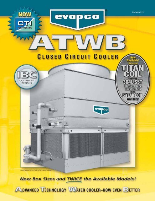
Design and Construction Features<br />
The Advanced Technology (AT) line of Closed Circuit Coolers has always reflected <strong>EVAPCO</strong>’s <strong>com</strong>mitment to<br />
product development. Its advanced design and owner oriented features provide many operational and<br />
performance advantages. The new and improved <strong>ATWB</strong> offers more models and box sizes and is<br />
†<br />
designed with IBC Compliant construction and CTI Certified Performance.<br />
NEW!<br />
CTI Certified<br />
NEW & Improved!<br />
• Easily removable for access<br />
• Improved design to keep sunlight<br />
out–preventing biological growth<br />
• Keeps water in while keeping dirt<br />
and debris out<br />
(Patent Pending)<br />
†<br />
NEW!<br />
Option<br />
Featuring Thermal-Pak ® XT Construction<br />
Introducing the Premier Closed Circuit Cooler Coil in the HVAC<br />
industry! The Titan provides:<br />
• 304L SST Construction for Superior Corrosion Resistance.<br />
• 5 Year Extended Coil Warranty – STANDARD!!<br />
• Patented Thermal-Pak ® XT elliptical tube design with elliptical<br />
return bends and extra tough construction.<br />
NEW!<br />
Easy Field Assembly<br />
• A new field assembly seam design<br />
which ensures easier assembly and<br />
fewer field seam leaks<br />
• Self-guiding channels guide the coil<br />
casing section into position improving<br />
the quality of the field seam<br />
• Eliminated up to 66% of fasteners<br />
(Patent Pending)<br />
Seismic<br />
and<br />
Wind<br />
Load<br />
Certification<br />
A T , U S S , U A T , U T C o o l i n g T o w e r s<br />
A T C - E a n d H T C E v a p o r a t i v e C o n d e n s e r s<br />
<strong>ATWB</strong><br />
Closed<br />
Circuit<br />
Coolers<br />
I B C S e r i a l N u m b e r : 4 3 3 8 7<br />
U n i t s D e s i g n e d a n d M a n u f a c t u r e d t o M e e t t h e<br />
S e i s m i c & W i n d L o a d R e q u i r e m e n t s o f :<br />
IBC<br />
2006<br />
ASCE-7<br />
NFPA<br />
5000<br />
I n d e p e n d e n t C e r t i f i c a t i o n B y :<br />
1 5 - 2 2 6 P A<br />
† Mark owned by the Cooling Technology Institute<br />
Efficient Drift Eliminators<br />
• Advanced design removes mist<br />
from the leaving airstream<br />
• Made from corrosion resistant<br />
PVC for long life<br />
(U.S. Patent No. 6315804)<br />
PVC Spray Distribution<br />
Header with ZM ® Nozzles<br />
• Nozzles are threaded into<br />
header at proper orientation<br />
• Large orifice fixed position<br />
nozzles prevent clogging<br />
• Threaded end caps for ease<br />
of cleaning<br />
NEW!<br />
IBC Certification Label<br />
• Provided with every<br />
unit to indicate independent<br />
certification<br />
and <strong>com</strong>pliance<br />
3<br />
®
4<br />
What is IBC?<br />
®<br />
International Building Code<br />
The International Building Code (IBC) is a <strong>com</strong>prehensive<br />
set of regulations addressing both the structural design<br />
and the installation requirements for building systems –<br />
including HVAC and industrial refrigeration equipment.<br />
The IBC is intended to replace BOCA’s The National<br />
Building Code, ICBO’s Uniform Building Code and SBCCI’s<br />
Standard Building Code.<br />
Compared to previous building codes that considered<br />
only the building structure and <strong>com</strong>ponent anchorage,<br />
the requirements contained within the IBC address<br />
anchorage, structural integrity, and the operational<br />
capability of a <strong>com</strong>ponent following either a seismic or<br />
wind load event. Simply stated, the IBC code<br />
provisions require that evaporative cooling<br />
equipment, and all other <strong>com</strong>ponents permanently<br />
installed on a structure, must be designed to meet<br />
the same seismic and wind load forces as the<br />
building to which they are attached.<br />
How Does IBC 2006 Apply to Closed<br />
Circuit Coolers?<br />
IBC COMPLIANCE<br />
In its continuing <strong>com</strong>mitment to be the leaders in evaporative cooling equipment design and services,<br />
<strong>EVAPCO</strong> <strong>ATWB</strong> Closed Circuit Coolers are now Independently Certified to withstand both Seismic<br />
and Wind Loads in ALL Geographic Locations and Installations in accordance with IBC 2006.<br />
Based on the project zip code and site design factors, calculations<br />
are made to determine the equivalent seismic<br />
“g force” and wind load (in pounds per square foot – psf)<br />
on the unit. The closed circuit cooler must be designed to<br />
withstand the greater of either the seismic or wind load.<br />
The New <strong>ATWB</strong> is offered with a choice of TWO<br />
structural design packages:<br />
• Standard Structural Design – For projects with<br />
≤ 1.0g seismic or 145 psf wind loads<br />
• Upgraded Structural Design – Required for<br />
projects with > 1.0g seismic or 145 psf max wind loads<br />
More than 80% of the United States has design criteria<br />
resulting in a seismic design force of 1.0g or below. These<br />
sites will be provided with the standard <strong>ATWB</strong> structural<br />
design. An upgraded structural design is available for<br />
installations with design criteria resulting in “g forces”<br />
greater than 1.0g. The highest “g force” location in<br />
North America is 5.12g. The highest wind load shown on<br />
the maps is 170 mph, which is approximately equal to 145<br />
psf velocity pressure. Therefore, the upgraded structural<br />
design package option for the New <strong>ATWB</strong> is<br />
designed for 5.12g and 145 psf making it applicable<br />
to ALL building locations in North America.<br />
Seismic Design<br />
The attached chart from the US Geological Survey<br />
Website (http://www.usgs.gov/) shows the potential seismic<br />
activity in the United States. Buildings constructed in<br />
the red, orange and yellow areas of the map may require<br />
the upgraded <strong>ATWB</strong> construction design based on the<br />
site seismic design factors and should be reviewed closely.<br />
Critical use facilities, such as hospitals, are also more likely<br />
to require the upgraded design.<br />
Map courtesy US Geological Survey website<br />
Highest Hazard<br />
32+<br />
24-32<br />
16-24<br />
%g 8-16<br />
4-8<br />
2-4<br />
0-2<br />
Lowest Hazard<br />
The project architect or civil engineer is responsible for<br />
determining the seismic design factors to be used for the<br />
building design. A mechanical consulting engineer and/or<br />
design build contractor then applies these factors to a<br />
series of charts and graphs to determine the appropriate<br />
seismic design factors based on the location of the installation<br />
and ultimately the “importance” of the facility.<br />
The specific factors necessary for seismic design as well as<br />
a sample seismic calculation are shown on the next page.
Wind Design<br />
The IBC 2006 code book includes a map of basic wind<br />
speed (3-second gust) by contour lines. However, local<br />
regulations may be more stringent than these published<br />
speeds. The specific factors necessary for wind load as well<br />
as a sample wind load calculation are shown on Page 7.<br />
Whichever design force - seismic or wind - is more<br />
severe for the building, governs the design of the<br />
building and all attached equipment.<br />
Design Implementation<br />
<strong>EVAPCO</strong> applies the given seismic and wind load information<br />
provided by the mechanical consulting engineer to<br />
determine the equipment design necessary to meet IBC<br />
requirements. This process ensures that the mechanical<br />
equipment and its <strong>com</strong>ponents are <strong>com</strong>pliant per the<br />
provisions of the IBC as given in the plans and specifications<br />
for the project. For design build projects, <strong>EVAPCO</strong> is<br />
equipped to look up the information and submit the<br />
resulting loads for approval.<br />
Independent Certification<br />
Per the most recent edition of the code, the <strong>EVAPCO</strong><br />
<strong>com</strong>pliance process included an exhaustive analysis by an<br />
independent approval agency. As required by the<br />
International<br />
Building Code,<br />
<strong>EVAPCO</strong> sup-<br />
plies a certificate<br />
of <strong>com</strong>pliance<br />
as part of<br />
its submittal<br />
documents. The<br />
certificate of<br />
<strong>com</strong>pliance<br />
demonstrates<br />
Wind Load Map Courtesy IBC 2006 Text –<br />
See full-sized map for location specific values<br />
Certificate<br />
of<br />
Compliance<br />
A T , U S S , U A T , U T C o o l i n g T o w e r s<br />
<strong>ATWB</strong>Closed<br />
Circuit<br />
Coolers<br />
HTC, A T C - E E v a p o r a t i v e C o n d e n s e r s<br />
A r e c e r t i f i e d t o m e e t o r e x c e e d t h e S e i s m i c a n d W i n d L o a d P r o v i s i o n s<br />
s e t f o r t h i n t h e a p p l i c a b l e b u i l d i n g c o d e s f o r t h i s p r o j e c t .<br />
T h e s e p r o d u c t s h a v e b e e n m a n u f a c t u r e d f o l l o w i n g a l l<br />
a p p l i c a b l e q u a l i t y a s s u r a n c e p r o g r a m s .<br />
A p p l i c a b l e B u i l d i n g C o d e s :<br />
I B C 2 0 0 6<br />
A S C E - 7<br />
N F P A 5 0 0 0<br />
R e f e r e n c e d R e p o r t :<br />
V M A - 4 3 3 8 7<br />
A p p r o v a l A g e n c y :<br />
V M C S e i s m i c C o n s u l t i n g G r o u p<br />
<strong>EVAPCO</strong>. . . Specialists<br />
in<br />
Heat<br />
Transfer<br />
<strong>Product</strong>s<br />
and<br />
Services.<br />
I D I B C C O C 0 0 1<br />
IBC COMPLIANCE<br />
that the equipment has been independently tested and<br />
analyzed in accordance with the IBC seismic and wind<br />
load requirements. Evapco has worked closely with the<br />
independent approval agency, The VMC Group, to <strong>com</strong>plete<br />
the independent equipment testing and analysis.<br />
If the seismic “g force” and wind “psf” load requirements<br />
for the project site are known, <strong>EVAPCO</strong>’s online equipment<br />
selection software, iES, will allow you to choose the<br />
required structural design package – either standard construction<br />
or upgraded construction.<br />
If the project requirements are unknown, the following<br />
calculations must be <strong>com</strong>pleted.<br />
For further questions regarding IBC <strong>com</strong>pliance, please<br />
contact your local <strong>EVAPCO</strong> Representative or visit<br />
www.evapco.<strong>com</strong>.<br />
When using the <strong>EVAPCO</strong> selection software to make a<br />
selection, these calculations are already incorporated<br />
into the selection process. Simply enter the required<br />
seismic factors and the Seismic Design Force and Wind<br />
Load will be calculated automatically!!<br />
Seismic Load Calculations<br />
The data required to calculate the seismic load are:<br />
Occupancy Category – I, II, III or IV depending on the<br />
nature of the building occupancy. Table 1604.5 in the IBC<br />
2006 Code Book defines each of the four categories in<br />
detail. In summary the four categories are:<br />
• Category I - structures that represent a low hazard<br />
to human life in the event of a failure.<br />
• Category III - structures that represent a substantial<br />
hazard to human life in the event of a failure.<br />
• Category IV - structures designated as essential<br />
facilities.<br />
• Category II - any structures not listed in I, III or IV.<br />
Site Classification – A, B, C, D, E or F based on the types<br />
of soil and their engineering properties. Table 1613.5.2 in<br />
the IBC 2006 Code Book defines each of the categories in<br />
detail. IBC specifies site class “D” when soil properties are<br />
unknown.<br />
Maximum Spectral Response Acceleration (Ss) –<br />
Numerical value found using the U.S. Geological (USGS)<br />
data based on the Zip Code of the project. This data<br />
point can be determined using the Ground Motion<br />
Parameter Calculator at http://www.usgs.gov/. Note the<br />
calculator assumes a site classification of B for the 0.2 second<br />
maximum Ss. The site coefficient (Fa), defined below,<br />
will correct for the actual site classification.<br />
5<br />
®
6<br />
®<br />
Site Coefficient (Fa) – Values ranging from 0.8 to 2.5<br />
determined based on the Ss and the Site Classification.<br />
Table 1613.5.3(1) in the IBC 2006 Code Book defines<br />
these values.<br />
Design Spectral Response Acceleration (SDS) – A calculated<br />
value using the values for Ss and Fa.<br />
SDS<br />
= 2<br />
3<br />
(Fa)(Ss)<br />
Amplification Factor (ap) – 2.5 for flexible <strong>com</strong>ponents<br />
or flexibly attached <strong>com</strong>ponents. Due to its low inherent<br />
natural frequencies, most evaporative cooling equipment<br />
falls under the definition of flexible. Therefore the<br />
default for Closed Circuit Coolers is 2.5. See Table 13.6-1<br />
in the American Society of Civil Engineers (ASCE)<br />
Standard 7-05, to which IBC often references, for more<br />
information.<br />
Response Modification Factor (Rp) – 2.5 for non-isolated<br />
evaporative cooling equipment. 2.0 for vibration isolated<br />
evaporative cooling equipment. Table 13-6.1 of<br />
ASCE 7-05 provides additional information.<br />
Component Operating Weight (Wp) – This weight term<br />
has been removed from the equation below, because<br />
<strong>EVAPCO</strong> is expressing the force in terms of g’s and not lbs.<br />
Importance Factor (Ip) – 1.5 for Occupancy Category IV,<br />
life safety <strong>com</strong>ponents required to function after a seismic<br />
event or <strong>com</strong>ponent containing hazardous content.<br />
1.0 for all other <strong>com</strong>ponents. ASCE 7-05 Section 13.1.3<br />
provides additional detail on importance factors.<br />
Installation Location (Z/h) – 0 for units installed at<br />
ground level. 1.0 for units installed on a rooftop. Per<br />
ASCE 7-05 Section 13.3, z = the height of the point of<br />
attachment of the <strong>com</strong>ponent and h = the relative roof<br />
height.<br />
Seismic Design Force, (Fp) – “G-force” that the unit<br />
must be able to withstand. This number is calculated<br />
using the factors described above. The New <strong>ATWB</strong> is<br />
offered with a choice of two structural design packages,<br />
consisting of:<br />
– Standard Structural Design ≤ 1.0g<br />
– Upgraded Structural Design – up to 5.12g (the<br />
maximum value for North America)<br />
IBC COMPLIANCE<br />
Seismic Load Sample Calculation<br />
The following example demonstrates the procedure for<br />
determining which structural design package a<br />
Community Hospital located in Charleston, SC (zip code<br />
29401) would require under the latest version of IBC. In<br />
this example, the closed circuit cooler will be installed on<br />
a roof, approximately 60 feet above grade. The unit will<br />
also be installed with a vibration isolation system.<br />
Step 1: Calculate the Design Spectral Response<br />
Acceleration (SDS)<br />
Where:<br />
SS = 1.495; using the USGS Ground Motion Parameter<br />
Calculator<br />
Fa = 1.0; from Table 1613.5.3(1) in the IBC 2006 Code<br />
Book assuming a Site Classification of D<br />
Step 2: Calculate the Seismic Design Force (Fp )<br />
Where:<br />
SDS<br />
= 2<br />
3<br />
(Fa)(Ss)<br />
= 2<br />
3<br />
1+2 z<br />
0.4 (aP)(SDS)(WP)<br />
( )<br />
FP = =<br />
RP<br />
h<br />
( IP )<br />
(1.0)(1.495)=0.9966<br />
0.4 (2.5)(0.9966)(1)<br />
2.0 1.5<br />
( )<br />
(1+2(1))=2.24g<br />
ap = 2.5; the default for cooling towers and closed<br />
circuit coolers<br />
SDS = 0.9966; as calculated in Step 1<br />
Wp = 1.0; the default for cooling towers and closed<br />
circuit coolers<br />
Rp = 2.0; the default for isolated equipment<br />
Ip = 1.5; the default for life safety <strong>com</strong>ponents<br />
z/h = 1.0; the default for units on a rooftop<br />
In order to meet Code requirements, the unit and its<br />
anchorage must be constructed to withstand 2.24g. This<br />
will require that the upgraded structure option be chosen<br />
to meet the seismic requirements of this project. Because<br />
the seismic load requires the upgraded structural design,<br />
the wind load calculation results will not change the<br />
design and are not required for this analysis.
Wind Load Calculations<br />
Note, both the standard construction and the upgraded<br />
construction <strong>ATWB</strong> Closed Circuit Cooler are designed to<br />
meet a wind load of 145 psf. Therefore, the following<br />
details are provided for informational purposes only.<br />
The data required to calculate the wind load are:<br />
Basic Wind Speed (V) – Numerical value, in miles per<br />
hour (mph) found in ASCE 7-05 Figures 6-1 (A,B,C).<br />
Wind Directionality Factor (Kd) – 0.85 for building<br />
<strong>com</strong>ponents and cladding. Table 6-4 of ASCE 7-05 provides<br />
additional information.<br />
Occupancy Category – I, II, III or IV depending on the<br />
nature of the building occupancy. Table 1604.5 in the<br />
IBC 2006 Code Book defines each of the categories in<br />
detail. This is the same Occupancy Category used in<br />
Seismic calculations.<br />
Importance Factor (I) – Numerical value between 0.77<br />
and 1.15 based on the Basic Wind Speed and the<br />
Occupancy Category. These values are found in Table 6-1<br />
of ASCE 7-05.<br />
Exposure Category – B, C or D as defined in Section<br />
6.5.6.3 of ASCE 7-05.<br />
Component Elevation (z) – The anchorage height of<br />
the unit in feet.<br />
Nominal Height of the Atmospheric Boundary Layer<br />
(zg) - Numerical value based on Exposure Category. These<br />
values are found in Table 6-2 of ASCE 7-05.<br />
3 second Gust-Speed power Law Exponent (α) -<br />
Numerical value based on Exposure Category. These<br />
values are found in Table 6-2 of ASCE 7-05.<br />
Velocity Pressure Exposure Coefficient (Kz) – A<br />
calculated value using the values for zg and α.<br />
KZ = 2.01<br />
z<br />
( zg)<br />
2<br />
( a )<br />
Topographic Factor (Kzt) – 1.0 default when<br />
topographic effects are not a factor. ASCE 7-05 Section<br />
6.5.7 provides additional detail on topographic factors.<br />
Velocity Pressure (qz) – This number in pounds per<br />
square foot (psf) is calculated using the factors described<br />
above. The New <strong>ATWB</strong> is offered with a choice of two<br />
structural design packages, consisting of:<br />
– Standard Design and Upgraded Structural Design –<br />
both up to 145 psf (the maximum value for North<br />
America)<br />
IBC COMPLIANCE<br />
Wind Load Sample Calculation<br />
The following example demonstrates the procedure to<br />
determine which structural design package a<br />
Condominium Building located in Miami, FL (zip code<br />
33101) would require under the latest version of IBC. In<br />
this example, the closed circuit cooler will be installed on<br />
the top of the 60 foot tall building.<br />
Step 1: Calculate the Exposure Category Coefficient (Kz)<br />
Where:<br />
z = 60; Installation Height<br />
zg = 700; from ASCE 7-05 Table 2 using an Exposure<br />
Category of D.<br />
α = 11.5; from ASCE 7-05 Table 2 using an Exposure<br />
Category of D.<br />
Step 2: Calculate the Velocity Pressure (qp)<br />
Where:<br />
( a )<br />
qp = 0.00256(Kz)(Kzt)(Kd)(V 2 )(I) =<br />
0.00256(1.31)(1.0)(0.85)(145 2 )(1.0) = 59.93psf<br />
Kz = 1.31; as calculated above.<br />
( )<br />
( 11.5)<br />
KZ = 2 2<br />
z<br />
60<br />
2.01<br />
= ( zg)<br />
2.01 =<br />
700<br />
1.31<br />
Kzt = 1.0; default when topographic effects are not a<br />
factor.<br />
Kd = 0.85; default for building <strong>com</strong>ponents and<br />
cladding.<br />
V = 145; wind speed from ASCE 7-05 Figure 6-1.<br />
I = 1.0; Based on an Occupancy Category of II.<br />
In order to meet Code requirements, the unit and its<br />
attachments must be designed and constructed to<br />
withstand 59.93 psf. Because the wind load does not<br />
dictate the closed circuit cooler design, the seismic load<br />
calculation must also be <strong>com</strong>pleted to determine if the<br />
results will change the unit design.<br />
7<br />
®
8<br />
®<br />
Principle of Operation<br />
The process fluid is circulated through the coil of the closed<br />
circuit cooler. Heat from the process fluid is dissipated<br />
through the coil tubes to the water cascading downward over<br />
the tubes. Simultaneously, air is drawn in through the air inlet<br />
louvers at the base of the cooler and travels upward over the<br />
coil opposite the water flow. A small portion of the water is<br />
evaporated which removes the heat. The warm moist air is<br />
drawn to the top of the closed circuit cooler by the fan and is<br />
discharged to the atmosphere. The remaining water falls to<br />
the sump at the bottom of the cooler where it is recirculated<br />
by the pump up through the water distribution system and<br />
back down over the coils.<br />
Hot Saturated<br />
Discharge Air<br />
Principle of Operation<br />
Maintenance Free ZM ® Spray Nozzle<br />
Water Distribution System<br />
<strong>EVAPCO</strong>’S Zero Maintenance ZM ® Spray<br />
Nozzle remains clog-free while providing<br />
even and constant water distribution for<br />
reliable, scale-free evaporative cooling<br />
under all operating conditions.<br />
The heavy duty nylon ZM ® Spray nozzles<br />
have a 1-5/16” diameter opening and a<br />
1-1/2” splash plate clearance enabling<br />
<strong>EVAPCO</strong> to use 75% fewer nozzles.<br />
Furthermore, the fixed position ZM ®<br />
nozzles are mounted in corrosion-free<br />
PVC water distribution pipes that have<br />
threaded end caps. Together, these<br />
elements <strong>com</strong>bine to provide unequaled<br />
coil coverage and scale prevention, and<br />
make the industry’s best performing<br />
non-corrosive, maintenance-free water<br />
distribution system.<br />
D ESIGN F EATURES<br />
Hot Water In<br />
Cooled<br />
Water Out<br />
Cool Dry<br />
Entering<br />
Air<br />
ZM ® Nozzle<br />
Cooling Coil<br />
All Evapco Closed Circuit Coolers utilize <strong>EVAPCO</strong>’s patented<br />
Thermal-Pak ® coil design which assures greater operating efficiency.<br />
The elliptical tube design allows for closer tube spacing,<br />
resulting in greater surface area per plan area than<br />
round-tube coil designs. In addition, the Thermal-Pak ® design<br />
has lower resistance to airflow and also permits greater water<br />
loading, making the Thermal-Pak ® coil the most effective<br />
design available.<br />
The coils are manufactured from high quality steel tubing<br />
following the most stringent quality control procedures.<br />
Each circuit is inspected to ensure the material quality and<br />
then tested before being assembled into a coil. Finally, the<br />
assembled coil is pneumatically tested at 400 psig under water<br />
to ensure it is leak free.<br />
To protect the coil against corrosion, it is placed in a heavy steel<br />
frame and then the entire assembly is dipped in molten zinc<br />
(hot-dip galvanized) at a temperature of approximately 800°F.<br />
NOW Evapco offers the .<br />
Manufactured from type 304L Stainless Steel, the TITAN COIL<br />
is manufactured using Evapco’s patented elliptical tube<br />
Thermal Pak ® design upgraded to Xtra Tough construction<br />
featuring: Xtra Durability, Xtra Corrosion<br />
Resistance, and an Xtra long<br />
5 YEAR coil warranty as<br />
standard.<br />
U.S. Patent No. 5,799,725<br />
Thermal-Pak ® Coil by <strong>EVAPCO</strong><br />
Round Tube Coil by Others<br />
Thermal-Pak ® Coil<br />
Note: Closed circuit coolers should only be used on sealed,<br />
pressurized systems. Continual aeration of the water in an<br />
open system can cause corrosion inside the tubes of the<br />
cooler leading to premature failure.
Efficient Drift Eliminators<br />
The <strong>ATWB</strong> is equipped with an efficient drift eliminator<br />
system that effectively reduces entrained water droplets from<br />
the air discharge to less than 0.001% of the spray water flow<br />
rate.<br />
The eliminators are constructed of non-corrosive PVC with a<br />
multi-pass design for maximum drift reduction. They are<br />
assembled in modular sections for easy removal and access to<br />
the water distribution system.<br />
In addition to reducing drift, the eliminators also function as<br />
effective debris screens which protect the spray system from<br />
sunlight and debris.<br />
Superior Air Inlet Louver and<br />
Screen Design – New & Improved<br />
<strong>EVAPCO</strong>’S WST Inlet Louvers (patent pending) keep water in<br />
and sunlight out of induced draft products. The unique nonplanar<br />
design is made from light-weight framed PVC sections<br />
which have no loose hardware, enabling easy unit access.<br />
Developed with <strong>com</strong>putational fluid dynamics (CFD) software,<br />
the louver’s air channels are optimized to maintain fluid<br />
dynamic and thermodynamic efficiency and block all line-ofsight<br />
paths into the basin eliminating splash-out; even when<br />
the fans are off. Additionally, algae growth is minimized by<br />
blocking all sunlight.<br />
The <strong>com</strong>bination of easy access, no splash-out and minimized<br />
algae growth saves the end user money on maintenance<br />
hours, water consumption and water treatment costs.<br />
Air Intake<br />
Splashout<br />
D ESIGN F EATURES<br />
Sunlight<br />
Debris<br />
Belt Drive Units -<br />
3’, 4’, 8-1/2’ and 17’ Wide Models<br />
The fan motor and drive assembly on these units are<br />
designed to allow easy servicing of the motor and<br />
adjustment of the belt tension from the exterior of the unit.<br />
A T.E.F.C. fan motor is mounted on the outside of these<br />
models. A protective cover swings away to allow servicing<br />
and belt adjustment.<br />
Belt Drive Units -<br />
10’, 12’, 20’, & 24’ Wide Models<br />
The fan motor and drive assembly are designed to allow easy<br />
servicing of the motor and adjustment of the belt tension<br />
from the exterior of the unit. The T.E.A.O. fan motor is<br />
located inside the fan casing on a rugged heavy duty motor<br />
base. The innovative motor base also features a unique<br />
locking mechanism for a positive adjustment.<br />
The motor base is<br />
designed to swing out<br />
through a very large,<br />
14 square foot access<br />
opening. This allows<br />
for easy servicing of<br />
the motor from<br />
outside of the unit.<br />
External Motor Mount<br />
Motor Base Assembly<br />
Motor Access<br />
9<br />
®
Engineering Data & Dimensions<br />
<strong>ATWB</strong> Models 3-2C3 to 3-5D3<br />
† Model Numbers end in “-Z” for units with Series Flow piping configuration. 3x3 <strong>ATWB</strong> units are only available in Series Flow and will require crossover<br />
piping which can either be supplied by the factory or by others. Model numbers will include “C” for units with Stainless Steel coil(s), “R” for units with<br />
Low Sound Fan(s) and “S” for units with an option that negates CTI certification.<br />
†† Heaviest section is the coil/fan section.<br />
* Gallons shown is water in suspension in unit and piping. Allow for additional water in bottom of remote sump to cover pump suction and strainer<br />
during operation (12” would normally be sufficient).<br />
▲ When a remote sump arrangement is selected, the spray pump, suction strainer and associated piping are omitted; the unit is provided with an<br />
oversized outlet to facilitate drainage to the remote sump.<br />
▲ Unit dimensions and coil connections may vary slightly from catalog. See factory certified prints for dimensions, quantity of coil connections, and<br />
piping configuration. Coil connections are 4” bevel for weld (BFW). Other connection types such as grooved for mechanical coupling or flanged are<br />
also available as options.<br />
10<br />
5-1/4<br />
A<br />
M<br />
5-1/8<br />
4-3/8<br />
1-7/8 3' 1/2"<br />
9<br />
15<br />
4 BFW<br />
FLUID IN<br />
4 BFW<br />
FLUID OUT<br />
1 MPT MAKE-UP<br />
2 FPT OVERFLOW<br />
19-3/4<br />
12-7/8<br />
3<br />
2 MPT DRAIN<br />
U<br />
E<br />
1/2<br />
FPT VENT<br />
<strong>ATWB</strong> Weights (lbs) Fans Spray Pump<br />
Coil Remote Sump<br />
Model Heaviest Volume Gallons* Conn. Operating Coil Upper Lower Height<br />
Number† Shipping Section†† Operating HP CFM HP GPM (Gallons) Required Size Weight (lbs) A U E H<br />
▲ Dimensions ▲<br />
<strong>ATWB</strong> 3-2C3-Z 1,150 870 1,680 1 4,600 3/4 50 16 45 6" 1,440 12" 5' 4-1/4" 2' 7-3/8" 7' 11-5/8"<br />
<strong>ATWB</strong> 3-3C3-Z 1,310 1,030 1,890 1 4,470 3/4 50 21 45 6" 1,650 20-1/2" 6' 3/4" 2' 7-3/8" 8' 8-1/8"<br />
<strong>ATWB</strong> 3-4C3-Z 1,450 1,170 2,070 1 4,340 3/4 50 26 45 6" 1,830 29" 6' 9-1/4" 2' 7-3/8" 9' 4-5/8"<br />
<strong>ATWB</strong> 3-4D3-Z 1,460 1,180 2,080 1.5 4,910 3/4 50 26 45 6" 1,840 29" 6' 9-1/4" 2' 7-3/8" 9' 4-5/8"<br />
<strong>ATWB</strong> 3-5C3-Z 1,600 1,320 2,260 1 4,210 3/4 50 31 45 6" 2,020 37-1/2" 7' 5-3/4" 2' 7-3/8" 10' 1-1/8"<br />
<strong>ATWB</strong> 3-5D3-Z 1,610 1,330 2,270 1.5 4,760 3/4 50 31 45 6" 2,030 37-1/2" 7' 5-3/4" 2' 7-3/8" 10' 1-1/8"<br />
H<br />
P<br />
14-3/4<br />
ACCESS<br />
DOOR<br />
ACCESS DOOR<br />
2' 11-3/4"<br />
Note: The number of coil connections doubles when the flow rate exceeds 450 GPM on 3x3 models. This required option is referred to as the High Flow coil configuration.<br />
M<br />
M
Selections for <strong>ATWB</strong> Closed Circuit Coolers are available from <strong>EVAPCO</strong>’s iES Equipment Selection Program.<br />
Please contact your local sales representative for more information on the iES program.<br />
Engineering Data & Dimensions<br />
<strong>ATWB</strong> Models 4-2E4 to 4-5F4<br />
5-1/4"<br />
1' 3/4"<br />
11-1/2" 1' 10"<br />
A<br />
M<br />
5-1/8<br />
4-3/8<br />
4 BFW<br />
FLUID IN<br />
4 BFW<br />
FLUID OUT<br />
1 MPT MAKE-UP<br />
2 FPT OVERFLOW<br />
12-7/8 19-3/4<br />
3<br />
2 MPT DRAIN<br />
U<br />
E<br />
H<br />
1/2 FPT<br />
VENT<br />
1-7/8 4' 1/2" 14-3/4 3' 11-3/4"<br />
P<br />
M<br />
M<br />
ACCESS DOOR<br />
Note: The number of coil connections doubles when the flow rate exceeds 450 GPM on 4x4 models. This required option is referred to as the High Flow coil configuration.<br />
<strong>ATWB</strong> Weights (lbs) Fans Spray Pump Coil<br />
Remote Sump<br />
Model Heaviest Volume Gallons* Conn. Operating Coil Upper Lower Height<br />
Number† Shipping Section†† Operating HP CFM HP GPM (Gallons) Required Size Weight (lbs) A U E H<br />
▲ Dimensions ▲<br />
<strong>ATWB</strong> 4-2E4-Z 1,710 1,320 2,660 2 8,650 3/4 90 26 80 6" 2,310 12" 5' 4-1/8" 3' 1-5/8" 8' 5-3/4"<br />
<strong>ATWB</strong> 4-3E4-Z 2,000 1,610 3,030 2 8,400 3/4 90 36 80 6" 2,680 19-1/2" 5' 11-5/8" 3' 1-5/8" 9' 1-1/4"<br />
<strong>ATWB</strong> 4-4E4-Z 2,250 1,860 3,360 2 8,160 3/4 90 46 80 6" 3,010 27" 6' 7-1/8" 3' 1-5/8" 9' 8-3/4"<br />
<strong>ATWB</strong> 4-4F4-Z 2,280 1,890 3,390 3 9,190 3/4 90 46 80 6" 3,040 27" 6' 7-1/8" 3' 1-5/8" 9' 8-3/4"<br />
<strong>ATWB</strong> 4-5E4-Z 2,520 2,130 3,710 2 7,910 3/4 90 56 80 6" 3,360 34-1/2" 7' 2-5/8" 3' 1-5/8" 10' 4-1/4"<br />
<strong>ATWB</strong> 4-5F4-Z 2,550 2,160 3,740 3 8,910 3/4 90 56 80 6" 3,390 34-1/2" 7' 2-5/8" 3' 1-5/8" 10' 4-1/4"<br />
† Model Numbers end in “-Z” for units with Series Flow piping configuration. 4x4 <strong>ATWB</strong> units are only available in Series Flow and will require crossover<br />
piping which can either be supplied by the factory or by others. Model numbers will include “C” for units with Stainless Steel coil(s), “R” for units with<br />
Low Sound Fan(s) and “S” for units with an option that negates CTI certification.<br />
†† Heaviest section is the coil/fan section.<br />
* Gallons shown is water in suspension in unit and piping. Allow for additional water in bottom of remote sump to cover pump suction and strainer<br />
during operation (12” would normally be sufficient).<br />
▲ When a remote sump arrangement is selected, the spray pump, suction strainer and associated piping are omitted; the unit is provided with an<br />
oversized outlet to facilitate drainage to the remote sump.<br />
▲ Unit dimensions and coil connections may vary slightly from catalog. See factory certified prints for dimensions, quantity of coil connections, and<br />
piping configuration. Coil connections are 4” bevel for weld (BFW). Other connection types such as grooved for mechanical coupling or flanged are<br />
also available as options.<br />
ACCESS<br />
DOOR<br />
11
Engineering Data & Dimensions<br />
<strong>ATWB</strong> Models 4-3E6 to 4-5G6<br />
12<br />
5-1/4"<br />
A<br />
1' 3/4"<br />
M<br />
1' 10-1/2"<br />
5-1/8<br />
4-3/8<br />
1-7/8 4' 1/2"<br />
4 BFW<br />
FLUID IN<br />
4 BFW<br />
FLUID OUT<br />
1 MPT MAKE-UP<br />
2 FPT OVERFLOW<br />
12-7/8 19-3/4<br />
3<br />
2 MPT DRAIN<br />
U<br />
E<br />
H<br />
1/2 FPT<br />
VENT<br />
P<br />
14-3/4<br />
M<br />
M<br />
5' 11-3/4"<br />
ACCESS DOOR<br />
Note: The number of coil connections doubles when the flow rate exceeds 450 GPM on 4x6 models. This required option is referred to as the High Flow coil configuration.<br />
<strong>ATWB</strong> Weights (lbs) Fans Spray Pump Coil Remote Sump<br />
Model Heaviest Volume Gallons* Conn. Operating Coil Upper Lower Height<br />
Number† Shipping Section†† Operating HP CFM HP GPM (Gallons) Required Size Weight (lbs) A U E H<br />
<strong>ATWB</strong> 4-3E6 2,750 2,240 4,270 2 10,990 3/4 135 52 120 6" 3,810 19-1/2" 5' 11-5/8" 3' 1-5/8" 9' 1-1/4"<br />
<strong>ATWB</strong> 4-3F6 2,780 2,270 4,300 3 12,580 3/4 135 52 120 6" 3,840 19-1/2" 5' 11-5/8" 3' 1-5/8" 9' 1-1/4"<br />
<strong>ATWB</strong> 4-3G6 2,790 2,280 4,310 5 14,590 3/4 135 52 120 6" 3,850 19-1/2" 5' 11-5/8" 3' 1-5/8" 9' 1-1/4"<br />
<strong>ATWB</strong> 4-4E6 3,120 2,610 4,770 2 10,670 3/4 135 67 120 6" 4,310 27" 6' 7-1/8" 3' 1-5/8" 9' 8-3/4"<br />
<strong>ATWB</strong> 4-4F6 3,150 2,640 4,800 3 12,210 3/4 135 67 120 6" 4,340 27" 6' 7-1/8" 3' 1-5/8" 9' 8-3/4"<br />
<strong>ATWB</strong> 4-4G6 3,160 2,650 4,810 5 14,160 3/4 135 67 120 6" 4,350 27" 6' 7-1/8" 3' 1-5/8" 9' 8-3/4"<br />
<strong>ATWB</strong> 4-5E6 3,530 3,020 5,300 2 10,350 3/4 135 83 120 6" 4,840 34-1/2" 7' 2-5/8" 3' 1-5/8" 10' 4-1/4"<br />
<strong>ATWB</strong> 4-5F6 3,560 3,050 5,330 3 11,840 3/4 135 83 120 6" 4,870 34-1/2" 7' 2-5/8" 3' 1-5/8" 10' 4-1/4"<br />
<strong>ATWB</strong> 4-5G6 3,570 3,060 5,340 5 13,740 3/4 135 83 120 6" 4,880 34-1/2" 7' 2-5/8" 3' 1-5/8" 10' 4-1/4"<br />
▲ Dimensions ▲<br />
† Model Numbers end in “-Z” for units with Series Flow piping configuration. Series Flow units may require additional coil connections and will require<br />
crossover piping. Model numbers will include “C” for units with Stainless Steel coil(s), “R” for units with Low Sound Fan(s) and “S” for units with an<br />
option that negates CTI certification.<br />
†† Heaviest section is the coil/fan section.<br />
* Gallons shown is water in suspension in unit and piping. Allow for additional water in bottom of remote sump to cover pump suction and strainer<br />
during operation (12” would normally be sufficient).<br />
▲ When a remote sump arrangement is selected, the spray pump, suction strainer and associated piping are omitted; the unit is provided with an<br />
oversized outlet to facilitate drainage to the remote sump.<br />
▲ Unit dimensions and coil connections may vary slightly from catalog. See factory certified prints for dimensions, quantity of coil connections, and<br />
piping configuration. Coil connections are 4” bevel for weld (BFW). Other connection types such as grooved for mechanical coupling or flanged are<br />
also available as options.<br />
ACCESS<br />
DOOR
Selections for <strong>ATWB</strong> Closed Circuit Coolers are available from <strong>EVAPCO</strong>’s iES Equipment Selection Program.<br />
Please contact your local sales representative for more information on the iES program.<br />
Engineering Data & Dimensions<br />
<strong>ATWB</strong> Models 4-3E9 to 4-5F9<br />
<strong>ATWB</strong> Models 4-3E12 to 4-5G12<br />
5-1/4"<br />
A<br />
1' 3/4"<br />
M<br />
1' 10-1/2"<br />
5-1/8<br />
4-3/8<br />
1-7/8 4' 1/2"<br />
4 BFW<br />
FLUID IN<br />
4 BFW<br />
FLUID OUT<br />
1 MPT MAKE-UP<br />
2 FPT OVERFLOW<br />
12-7/8 19-3/4<br />
3<br />
2 MPT DRAIN<br />
H<br />
1/2<br />
FPT VENT<br />
P<br />
M<br />
ACCESS<br />
DOOR<br />
14-3/4 L<br />
Note: The number of coil connections doubles when the flow rate exceeds 450 GPM on <strong>ATWB</strong> 4x9 and 4x12 models.<br />
This required option is referred to as the High Flow coil configuration.<br />
U<br />
E<br />
M<br />
ACCESS DOOR<br />
M<br />
M<br />
ACCESS DOOR<br />
<strong>ATWB</strong> Weights (lbs) Fans Spray Pump Coil Remote Sump<br />
Model Heaviest Volume Gallons* Conn. Operating Coil Upper Lower Height Length<br />
Number† Shipping Section†† Operating HP CFM HP GPM (Gallons) Required Size Weight (lbs) A U E H L<br />
<strong>ATWB</strong> 4-3E9 4,050 3,380 6,250 (2) 2 18,110 1 200 76 180 6" 5,630 19-1/2" 5' 11-5/8" 3' 1-5/8" 9' 1-1/4" 8' 11-3/4"<br />
<strong>ATWB</strong> 4-3F9 4,110 3,440 6,310 (2) 3 20,520 1 200 76 180 6" 5,690 19-1/2" 5' 11-5/8" 3' 1-5/8" 9' 1-1/4" 8' 11-3/4"<br />
<strong>ATWB</strong> 4-4E9 4,600 3,930 6,990 (2) 2 17,580 1 200 99 180 6" 6,370 27" 6' 7-1/8" 3' 1-5/8" 9' 8-3/4" 8' 11-3/4"<br />
<strong>ATWB</strong> 4-4F9 4,660 3,990 7,050 (2) 3 19,920 1 200 99 180 6" 6,430 27" 6' 7-1/8" 3' 1-5/8" 9' 8-3/4" 8' 11-3/4"<br />
<strong>ATWB</strong> 4-5E9 5,190 4,520 7,780 (2) 2 17,060 1 200 122 180 6" 7,160 34-1/2" 7' 2-5/8" 3' 1-5/8" 10' 4-1/4" 8' 11-3/4"<br />
<strong>ATWB</strong> 4-5F9 5,250 4,580 7,840 (2) 3 19,320 1 200 122 180 6" 7,220 34-1/2" 7' 2-5/8" 3' 1-5/8" 10' 4-1/4" 8' 11-3/4"<br />
<strong>ATWB</strong> 4-3E12 4,890 4,070 7,790 (2) 2 21,990 1.5 270 100 230 8" 7,010 19-1/2" 5' 11-5/8" 3' 1-5/8" 9' 1-1/4" 11' 11-3/4"<br />
<strong>ATWB</strong> 4-3F12 4,950 4,130 7,850 (2) 3 25,170 1.5 270 100 230 8" 7,070 19-1/2" 5' 11-5/8" 3' 1-5/8" 9' 1-1/4" 11' 11-3/4"<br />
<strong>ATWB</strong> 4-3G12 4,970 4,150 7,870 (2) 5 29,190 1.5 270 100 230 8" 7,090 19-1/2" 5' 11-5/8" 3' 1-5/8" 9' 1-1/4" 11' 11-3/4"<br />
<strong>ATWB</strong> 4-4E12 5,630 4,810 8,790 (2) 2 21,350 1.5 270 131 230 8" 8,010 27" 6' 7-1/8" 3' 1-5/8" 9' 8-3/4" 11' 11-3/4"<br />
<strong>ATWB</strong> 4-4F12 5,690 4,870 8,850 (2) 3 24,440 1.5 270 131 230 8" 8,070 27" 6' 7-1/8" 3' 1-5/8" 9' 8-3/4" 11' 11-3/4"<br />
<strong>ATWB</strong> 4-4G12 5,710 4,890 8,870 (2) 5 28,340 1.5 270 131 230 8" 8,090 27" 6' 7-1/8" 3' 1-5/8" 9' 8-3/4" 11' 11-3/4"<br />
<strong>ATWB</strong> 4-5E12 6,430 5,610 9,850 (2) 2 20,710 1.5 270 162 230 8" 9,070 34-1/2" 7' 2-5/8" 3' 1-5/8" 10' 4-1/4" 11' 11-3/4"<br />
<strong>ATWB</strong> 4-5F12 6,490 5,670 9,910 (2) 3 23,700 1.5 270 162 230 8" 9,130 34-1/2" 7' 2-5/8" 3' 1-5/8" 10' 4-1/4" 11' 11-3/4"<br />
<strong>ATWB</strong> 4-5G12 6,510 5,690 9,930 (2) 5 27,490 1.5 270 162 230 8" 9,150 34-1/2" 7' 2-5/8" 3' 1-5/8" 10' 4-1/4" 11' 11-3/4"<br />
▲ Dimensions ▲<br />
† Model Numbers end in “-Z” for units with Series Flow piping configuration. Series Flow units may require additional coil connections and will require<br />
crossover piping. Model numbers will include “C” for units with Stainless Steel coil(s), “R” for units with Low Sound Fan(s) and “S” for units with an<br />
option that negates CTI certification.<br />
†† Heaviest section is the coil/fan section.<br />
* Gallons shown is water in suspension in unit and piping. Allow for additional water in bottom of remote sump to cover pump suction and strainer<br />
during operation (12” would normally be sufficient).<br />
▲ When a remote sump arrangement is selected, the spray pump, suction strainer and associated piping are omitted; the unit is provided with an<br />
oversized outlet to facilitate drainage to the remote sump.<br />
▲ Unit dimensions and coil connections may vary slightly from catalog. See factory certified prints for dimensions, quantity of coil connections, and<br />
piping configuration. Coil connections are 4” bevel for weld (BFW). Other connection types such as grooved for mechanical coupling or flanged are<br />
also available as options.<br />
ACCESS<br />
DOOR<br />
13
Engineering Data & Dimensions<br />
<strong>ATWB</strong> Models 9-3G8 to 9-7J8<br />
14<br />
21-3/8<br />
(2) 4 BFW<br />
FLUID IN<br />
23-1/8<br />
A<br />
2 MPT<br />
MAKE-UP<br />
3<br />
2 MPT<br />
DRAIN<br />
5-1/4<br />
4-1/4<br />
61-1/2<br />
7' 5-7/8"<br />
45-1/4 22-1/2<br />
3 MPT<br />
OVERFLOW<br />
(2) 4 BFW<br />
FLUID OUT<br />
15<br />
6<br />
U<br />
E<br />
H<br />
13-3/4<br />
P<br />
30-5/8<br />
(2) 1/2 FPT VENT<br />
8' 5-1/2"<br />
Swing Out Radius of Motor Cover<br />
ACCESS DOOR<br />
Note: The number of coil connections doubles when the flow rate exceeds 900 GPM on <strong>ATWB</strong> 9x8 models. This required option is referred to as the High Flow coil configuration.<br />
<strong>ATWB</strong> Weights (lbs) Fans Spray Pump Coil Remote Sump<br />
Model Heaviest Volume Gallons* Conn. Operating Coil Upper Lower Height<br />
Number† Shipping Section†† Operating HP CFM HP GPM (Gallons) Required Size Weight (lbs) A U E H<br />
<strong>ATWB</strong> 9-3G8 6,770 5,470 10,190 5 29,190 2 340 143 220 8" 9,090 19-1/2" 6' 7" 4' 1/4" 10' 7-1/4"<br />
<strong>ATWB</strong> 9-3H8 6,820 5,520 10,240 7.5 33,410 2 340 143 220 8" 9,140 19-1/2" 6' 7" 4' 1/4" 10' 7-1/4"<br />
<strong>ATWB</strong> 9-3I8 6,830 5,530 10,250 10 36,580 2 340 143 220 8" 9,150 19-1/2" 6' 7" 4' 1/4" 10' 7-1/4"<br />
<strong>ATWB</strong> 9-3J8 6,960 5,660 10,380 15 40,980 2 340 143 220 8" 9,280 19-1/2" 6' 7" 4' 1/4" 10' 7-1/4"<br />
<strong>ATWB</strong> 9-4G8 7,730 6,430 11,510 5 28,340 2 340 187 220 8" 10,410 27" 7' 2-1/2" 4' 1/4" 11' 2-3/4"<br />
<strong>ATWB</strong> 9-4H8 7,780 6,480 11,560 7.5 32,440 2 340 187 220 8" 10,460 27" 7' 2-1/2" 4' 1/4" 11' 2-3/4"<br />
<strong>ATWB</strong> 9-4I8 7,790 6,490 11,570 10 35,520 2 340 187 220 8" 10,470 27" 7' 2-1/2" 4' 1/4" 11' 2-3/4"<br />
<strong>ATWB</strong> 9-4J8 7,920 6,620 11,700 15 39,790 2 340 187 220 8" 10,600 27" 7' 2-1/2" 4' 1/4" 11' 2-3/4"<br />
<strong>ATWB</strong> 9-5H8 8,820 7,520 12,970 7.5 31,470 2 340 230 220 8" 11,870 34-1/2" 7' 10" 4' 1/4" 11' 10-1/4"<br />
<strong>ATWB</strong> 9-5I8 8,830 7,530 12,980 10 34,450 2 340 230 220 8" 11,880 34-1/2" 7' 10" 4' 1/4" 11' 10-1/4"<br />
<strong>ATWB</strong> 9-5J8 8,960 7,660 13,110 15 38,590 2 340 230 220 8" 12,010 34-1/2" 7' 10" 4' 1/4" 11' 10-1/4"<br />
<strong>ATWB</strong> 9-6H8 9,850 8,550 14,360 7.5 30,500 2 340 274 220 8" 13,260 42" 8' 5-1/2" 4' 1/4" 12' 5-3/4"<br />
<strong>ATWB</strong> 9-6I8 9,860 8,560 14,370 10 33,390 2 340 274 220 8" 13,270 42" 8' 5-1/2" 4' 1/4" 12' 5-3/4"<br />
<strong>ATWB</strong> 9-6J8 9,990 8,690 14,500 15 37,400 2 340 274 220 8" 13,400 42" 8' 5-1/2" 4' 1/4" 12' 5-3/4"<br />
<strong>ATWB</strong> 9-7H8 10,960 9,660 15,840 7.5 29,520 2 340 318 220 8" 14,740 47-3/4" 8' 11-1/4" 4' 1/4" 12' 11-1/2"<br />
<strong>ATWB</strong> 9-7I8 10,970 9,670 15,850 10 32,320 2 340 318 220 8" 14,750 47-3/4" 8' 11-1/4" 4' 1/4" 12' 11-1/2"<br />
<strong>ATWB</strong> 9-7J8 11,100 9,800 15,980 15 36,210 2 340 318 220 8" 14,880 47-3/4" 8' 11-1/4" 4' 1/4" 12' 11-1/2"<br />
▲ Dimensions ▲<br />
† Model Numbers end in “-Z” for units with Series Flow piping configuration. Series Flow units may require additional coil connections and will<br />
require crossover piping. Model numbers will include “C” for units with Stainless Steel coil(s), “R” for units with Low Sound Fan(s) and “S” for units<br />
with an option that negates CTI certification.<br />
†† Heaviest section is the coil/fan section.<br />
* Gallons shown is water in suspension in unit and piping. Allow for additional water in bottom of remote sump to cover pump suction and<br />
strainer during operation (12” would normally be sufficient).<br />
▲ When a remote sump arrangement is selected, the spray pump, suction strainer and associated piping are omitted; the unit is provided with an<br />
oversized outlet to facilitate drainage to the remote sump.<br />
▲ Unit dimensions and coil connections may vary slightly from catalog. See factory certified prints for dimensions, quantity of coil connections,<br />
and piping configuration. Coil connections are 4” bevel for weld (BFW). Other connection types such as grooved for mechanical coupling or<br />
flanged are also available as options.<br />
ACCESS<br />
DOOR
Selections for <strong>ATWB</strong> Closed Circuit Coolers are available from <strong>EVAPCO</strong>’s iES Equipment Selection Program.<br />
Please contact your local sales representative for more information on the iES program.<br />
Engineering Data & Dimensions<br />
<strong>ATWB</strong> Models 9-3H9 to 9-7K9<br />
21-3/8<br />
(2) 4 BFW<br />
FLUID IN<br />
23-1/8<br />
A<br />
2 MPT<br />
MAKE-UP<br />
3<br />
2 MPT<br />
DRAIN<br />
5-1/4<br />
4-1/4<br />
67-1/4<br />
8' 5-1/2"<br />
48-3/4 26-3/8<br />
3 MPT<br />
OVERFLOW<br />
(2) 4 BFW<br />
FLUID OUT<br />
15<br />
6<br />
U<br />
E<br />
H<br />
15-5/8<br />
P<br />
30-5/8<br />
(2) 1/2 FPT VENT<br />
8' 11-1/2"<br />
Swing Out Radius of Motor Cover<br />
ACCESS DOOR<br />
Note: The number of coil connections doubles when the flow rate exceeds 900 GPM on <strong>ATWB</strong> 9x9 models. This required option is referred to as the High Flow coil configuration.<br />
<strong>ATWB</strong> Weights (lbs) Fans Spray Pump Coil Remote Sump<br />
Model Heaviest Volume Gallons* Conn. Operating Coil Upper Lower Height<br />
Number† Shipping Section†† Operating HP CFM HP GPM (Gallons) Required Size Weight (lbs) A U E H<br />
<strong>ATWB</strong> 9-3H9 8,030 6,590 12,020 7.5 37,660 2 410 164 250 8" 10,740 19-1/2" 6' 11-1/2" 4' 3-7/8" 11' 3-3/8"<br />
<strong>ATWB</strong> 9-3I9 8,040 6,600 12,030 10 41,440 2 410 164 250 8" 10,750 19-1/2" 6' 11-1/2" 4' 3-7/8" 11' 3-3/8"<br />
<strong>ATWB</strong> 9-3J9 8,170 6,730 12,160 15 46,620 2 410 164 250 8" 10,880 19-1/2" 6' 11-1/2" 4' 3-7/8" 11' 3-3/8"<br />
<strong>ATWB</strong> 9-3K9 8,230 6,790 12,220 20 50,540 2 410 164 250 8" 10,940 19-1/2" 6' 11-1/2" 4' 3-7/8" 11' 3-3/8"<br />
<strong>ATWB</strong> 9-4H9 9,190 7,750 13,590 7.5 36,560 2 410 215 250 8" 12,310 27" 7' 7" 4' 3-7/8" 11' 10-7/8"<br />
<strong>ATWB</strong> 9-4I9 9,200 7,760 13,600 10 40,240 2 410 215 250 8" 12,320 27" 7' 7" 4' 3-7/8" 11' 10-7/8"<br />
<strong>ATWB</strong> 9-4J9 9,330 7,890 13,730 15 45,270 2 410 215 250 8" 12,450 27" 7' 7" 4' 3-7/8" 11' 10-7/8"<br />
<strong>ATWB</strong> 9-4K9 9,390 7,950 13,790 20 49,060 2 410 215 250 8" 12,510 27" 7' 7" 4' 3-7/8" 11' 10-7/8"<br />
<strong>ATWB</strong> 9-5H9 10,450 9,010 15,270 7.5 35,460 2 410 265 250 8" 13,990 34-1/2" 8' 2-1/2" 4' 3-7/8" 12' 6-3/8"<br />
<strong>ATWB</strong> 9-5I9 10,460 9,020 15,280 10 39,030 2 410 265 250 8" 14,000 34-1/2" 8' 2-1/2" 4' 3-7/8" 12' 6-3/8"<br />
<strong>ATWB</strong> 9-5J9 10,590 9,150 15,410 15 43,910 2 410 265 250 8" 14,130 34-1/2" 8' 2-1/2" 4' 3-7/8" 12' 6-3/8"<br />
<strong>ATWB</strong> 9-5K9 10,650 9,210 15,470 20 47,590 2 410 265 250 8" 14,190 34-1/2" 8' 2-1/2" 4' 3-7/8" 12' 6-3/8"<br />
<strong>ATWB</strong> 9-6I9 11,690 10,250 16,930 10 37,820 2 410 315 250 8" 15,650 42" 8' 10" 4' 3-7/8" 13' 1-7/8"<br />
<strong>ATWB</strong> 9-6J9 11,820 10,380 17,060 15 42,550 2 410 315 250 8" 15,780 42" 8' 10" 4' 3-7/8" 13' 1-7/8"<br />
<strong>ATWB</strong> 9-6K9 11,880 10,440 17,120 20 46,120 2 410 315 250 8" 15,840 42" 8' 10" 4' 3-7/8" 13' 1-7/8"<br />
<strong>ATWB</strong> 9-7I9 13,200 11,760 18,860 10 36,620 2 410 365 250 8" 17,580 47-3/4" 9' 3-3/4" 4' 3-7/8" 13' 7-5/8"<br />
<strong>ATWB</strong> 9-7J9 13,330 11,890 18,990 15 41,190 2 410 365 250 8" 17,710 47-3/4" 9' 3-3/4" 4' 3-7/8" 13' 7-5/8"<br />
<strong>ATWB</strong> 9-7K9 13,390 11,950 19,050 20 44,650 2 410 365 250 8" 17,770 47-3/4" 9' 3-3/4" 4' 3-7/8" 13' 7-5/8"<br />
▲ Dimensions ▲<br />
† Model Numbers end in “-Z” for units with Series Flow piping configuration. Series Flow units may require additional coil connections and will require<br />
crossover piping. Model numbers will include “C” for units with Stainless Steel coil(s), “R” for units with Low Sound Fan(s) and “S” for units with an<br />
option that negates CTI certification.<br />
†† Heaviest section is the coil/fan section.<br />
* Gallons shown is water in suspension in unit and piping. Allow for additional water in bottom of remote sump to cover pump suction and strainer<br />
during operation (12” would normally be sufficient).<br />
▲ When a remote sump arrangement is selected, the spray pump, suction strainer and associated piping are omitted; the unit is provided with an<br />
oversized outlet to facilitate drainage to the remote sump.<br />
▲ Unit dimensions and coil connections may vary slightly from catalog. See factory certified prints for dimensions, quantity of coil connections, and<br />
piping configuration. Coil connections are 4” bevel for weld (BFW). Other connection types such as grooved for mechanical coupling or flanged are<br />
also available as options.<br />
ACCESS<br />
DOOR<br />
15
Engineering Data & Dimensions<br />
<strong>ATWB</strong> Models 9-3H11 to 9-7L11<br />
16<br />
21-3/8<br />
(2) 4 BFW<br />
FLUID IN<br />
23-1/8<br />
A<br />
2 MPT<br />
MAKE-UP<br />
3<br />
2 MPT<br />
DRAIN<br />
5-1/4<br />
4-1/4<br />
67-1/4<br />
8' 5-1/2"<br />
48-3/4 26-3/8<br />
3 MPT<br />
OVERFLOW<br />
(2) 4 BFW<br />
FLUID OUT<br />
15<br />
6<br />
U<br />
E<br />
H<br />
15-5/8<br />
P<br />
30-5/8<br />
(2) 1/2 FPT VENT<br />
10' 5-1/2"<br />
Swing Out Radius of Motor Cover<br />
ACCESS DOOR<br />
Note: The number of coil connections doubles when the flow rate exceeds 900 GPM on <strong>ATWB</strong> 9x11 models. This required option is referred to as the High Flow coil configuration.<br />
<strong>ATWB</strong> Weights (lbs) Fans Spray Pump<br />
Coil<br />
Remote Sump<br />
Model Heaviest Volume Gallons* Conn. Operating Coil Upper Lower Height<br />
Number† Shipping Section†† Operating HP CFM HP GPM (Gallons) Required Size Weight (lbs) A U E H<br />
<strong>ATWB</strong> 9-3H11 9,230 7,590 13,910 7.5 41,750 3 500 190 290 10" 12,400 19-1/2" 6' 11-1/2" 4' 3-7/8" 11' 3-3/8"<br />
<strong>ATWB</strong> 9-3I11 9,250 7,610 13,930 10 45,960 3 500 190 290 10" 12,420 19-1/2" 6' 11-1/2" 4' 3-7/8" 11' 3-3/8"<br />
<strong>ATWB</strong> 9-3J11 9,370 7,730 14,050 15 52,130 3 500 190 290 10" 12,540 19-1/2" 6' 11-1/2" 4' 3-7/8" 11' 3-3/8"<br />
<strong>ATWB</strong> 9-3K11 9,430 7,790 14,110 20 56,500 3 500 190 290 10" 12,600 19-1/2" 6' 11-1/2" 4' 3-7/8" 11' 3-3/8"<br />
<strong>ATWB</strong> 9-4H11 10,580 8,940 15,750 7.5 40,540 3 500 249 290 10" 14,240 27" 7' 7" 4' 3-7/8" 11' 10-7/8"<br />
<strong>ATWB</strong> 9-4I11 10,600 8,960 15,770 10 44,620 3 500 249 290 10" 14,260 27" 7' 7" 4' 3-7/8" 11' 10-7/8"<br />
<strong>ATWB</strong> 9-4J11 10,720 9,080 15,890 15 50,610 3 500 249 290 10" 14,380 27" 7' 7" 4' 3-7/8" 11' 10-7/8"<br />
<strong>ATWB</strong> 9-4K11 10,780 9,140 15,950 20 54,860 3 500 249 290 10" 14,440 27" 7' 7" 4' 3-7/8" 11' 10-7/8"<br />
<strong>ATWB</strong> 9-5I11 12,090 10,450 17,750 10 43,280 3 500 307 290 10" 16,240 34-1/2" 8' 2-1/2" 4' 3-7/8" 12' 6-3/8"<br />
<strong>ATWB</strong> 9-5J11 12,210 10,570 17,870 15 49,090 3 500 307 290 10" 16,360 34-1/2" 8' 2-1/2" 4' 3-7/8" 12' 6-3/8"<br />
<strong>ATWB</strong> 9-5K11 12,270 10,630 17,930 20 53,210 3 500 307 290 10" 16,420 34-1/2" 8' 2-1/2" 4' 3-7/8" 12' 6-3/8"<br />
<strong>ATWB</strong> 9-5L11 12,300 10,660 17,960 25 56,640 3 500 307 290 10" 16,450 34-1/2" 8' 2-1/2" 4' 3-7/8" 12' 6-3/8"<br />
<strong>ATWB</strong> 9-6J11 13,640 12,000 19,790 15 47,570 3 500 366 290 10" 18,280 42" 8' 10" 4' 3-7/8" 13' 1-7/8"<br />
<strong>ATWB</strong> 9-6K11 13,700 12,060 19,850 20 51,560 3 500 366 290 10" 18,340 42" 8' 10" 4' 3-7/8" 13' 1-7/8"<br />
<strong>ATWB</strong> 9-6L11 13,730 12,090 19,880 25 54,890 3 500 366 290 10" 18,370 42" 8' 10" 4' 3-7/8" 13' 1-7/8"<br />
<strong>ATWB</strong> 9-7J11 15,390 13,750 22,030 15 46,060 3 500 425 290 10" 20,520 47-3/4" 9' 3-3/4" 4' 3-7/8" 13' 7-5/8"<br />
<strong>ATWB</strong> 9-7K11 15,450 13,810 22,090 20 49,920 3 500 425 290 10" 20,580 47-3/4" 9' 3-3/4" 4' 3-7/8" 13' 7-5/8"<br />
<strong>ATWB</strong> 9-7L11 15,480 13,840 22,120 25 53,140 3 500 425 290 10" 20,610 47-3/4" 9' 3-3/4" 4' 3-7/8" 13' 7-5/8"<br />
▲ Dimensions ▲<br />
† Model Numbers end in “-Z” for units with Series Flow piping configuration. Series Flow units may require additional coil connections and will<br />
require crossover piping. Model numbers will include “C” for units with Stainless Steel coil(s), “R” for units with Low Sound Fan(s) and “S” for units<br />
with an option that negates CTI certification.<br />
†† Heaviest section is the coil/fan section.<br />
* Gallons shown is water in suspension in unit and piping. Allow for additional water in bottom of remote sump to cover pump suction and<br />
strainer during operation (12” would normally be sufficient).<br />
▲ When a remote sump arrangement is selected, the spray pump, suction strainer and associated piping are omitted; the unit is provided with an<br />
oversized outlet to facilitate drainage to the remote sump.<br />
▲ Unit dimensions and coil connections may vary slightly from catalog. See factory certified prints for dimensions, quantity of coil connections,<br />
and piping configuration. Coil connections are 4” bevel for weld (BFW). Other connection types such as grooved for mechanical coupling or<br />
flanged are also available as options.<br />
ACCESS<br />
DOOR
Selections for <strong>ATWB</strong> Closed Circuit Coolers are available from <strong>EVAPCO</strong>’s iES Equipment Selection Program.<br />
Please contact your local sales representative for more information on the iES program.<br />
Engineering Data & Dimensions<br />
<strong>ATWB</strong> Models 9-3I12 to 9-7M12<br />
21-3/8<br />
(2) 4 BFW<br />
FLUID IN<br />
23-1/8<br />
A<br />
2 MPT<br />
MAKE-UP<br />
3<br />
2 MPT<br />
DRAIN<br />
5-1/4<br />
4-1/4<br />
67-1/4<br />
8' 5-1/2"<br />
48-3/4 26-3/8<br />
3 MPT<br />
OVERFLOW<br />
(2) 4 BFW<br />
FLUID OUT<br />
15<br />
6<br />
U<br />
E<br />
H<br />
15-5/8<br />
P<br />
(2) 1/2 FPT VENT<br />
30-5/8<br />
11' 11-3/4"<br />
Swing Out Radius of Motor Cover<br />
ACCESS DOOR<br />
Note: The number of coil connections doubles when the flow rate exceeds 900 GPM on <strong>ATWB</strong> 9x12 models. This required option is referred to as the High Flow coil configuration.<br />
<strong>ATWB</strong> Weights (lbs) Fans Spray Pump Coil Remote Sump<br />
Model Heaviest Volume Gallons* Conn. Operating Coil Upper Lower Heigh<br />
Number† Shipping Section†† Operating HP CFM HP GPM (Gallons) Required Size Weight (lbs) A U E H<br />
<strong>ATWB</strong> 9-3I12 9,940 8,140 15,380 10 50,310 3 550 216 330 10" 13,670 19-1/2" 6' 11-1/2" 4' 8-1/4" 11' 7-3/4"<br />
<strong>ATWB</strong> 9-3J12 10,070 8,270 15,510 15 57,490 3 550 216 330 10" 13,800 19-1/2" 6' 11-1/2" 4' 8-1/4" 11' 7-3/4"<br />
<strong>ATWB</strong> 9-3K12 10,130 8,330 15,570 20 62,310 3 550 216 330 10" 13,860 19-1/2" 6' 11-1/2" 4' 8-1/4" 11' 7-3/4"<br />
<strong>ATWB</strong> 9-3L12 10,160 8,360 15,600 25 66,330 3 550 216 330 10" 13,890 19-1/2" 6' 11-1/2" 4' 8-1/4" 11' 7-3/4"<br />
<strong>ATWB</strong> 9-4I12 11,520 9,720 17,520 10 48,850 3 550 283 330 10" 15,810 27" 7' 7" 4' 8-1/4" 12' 3-1/4"<br />
<strong>ATWB</strong> 9-4J12 11,650 9,850 17,650 15 55,810 3 550 283 330 10" 15,940 27" 7' 7" 4' 8-1/4" 12' 3-1/4"<br />
<strong>ATWB</strong> 9-4K12 11,710 9,910 17,710 20 60,490 3 550 283 330 10" 16,000 27" 7' 7" 4' 8-1/4" 12' 3-1/4"<br />
<strong>ATWB</strong> 9-4L12 11,740 9,940 17,740 25 64,390 3 550 283 330 10" 16,030 27" 7' 7" 4' 8-1/4" 12' 3-1/4"<br />
<strong>ATWB</strong> 9-5J12 13,230 11,430 19,790 15 54,140 3 550 350 330 10" 18,080 34-1/2" 8' 2-1/2" 4' 8-1/4" 12' 10-3/4"<br />
<strong>ATWB</strong> 9-5K12 13,290 11,490 19,850 20 58,680 3 550 350 330 10" 18,140 34-1/2" 8' 2-1/2" 4' 8-1/4" 12' 10-3/4"<br />
<strong>ATWB</strong> 9-5L12 13,320 11,520 19,880 25 62,460 3 550 350 330 10" 18,170 34-1/2" 8' 2-1/2" 4' 8-1/4" 12' 10-3/4"<br />
<strong>ATWB</strong> 9-5M12 13,370 11,570 19,930 30 65,730 3 550 350 330 10" 18,220 34-1/2" 8' 2-1/2" 4' 8-1/4" 12' 10-3/4"<br />
<strong>ATWB</strong> 9-6J12 14,870 13,070 21,990 15 52,460 3 550 418 330 10" 20,280 42" 8' 10" 4' 8-1/4" 13' 6-1/4"<br />
<strong>ATWB</strong> 9-6K12 14,930 13,130 22,050 20 56,860 3 550 418 330 10" 20,340 42" 8' 10" 4' 8-1/4" 13' 6-1/4"<br />
<strong>ATWB</strong> 9-6L12 14,960 13,160 22,080 25 60,530 3 550 418 330 10" 20,370 42" 8' 10" 4' 8-1/4" 13' 6-1/4"<br />
<strong>ATWB</strong> 9-6M12 15,010 13,210 22,130 30 63,700 3 550 418 330 10" 20,420 42" 8' 10" 4' 8-1/4" 13' 6-1/4"<br />
<strong>ATWB</strong> 9-7J12 16,800 15,000 24,480 15 50,790 3 550 485 330 10" 22,770 47-3/4" 9' 3-3/4" 4' 8-1/4" 14' 0"<br />
<strong>ATWB</strong> 9-7K12 16,860 15,060 24,540 20 55,050 3 550 485 330 10" 22,830 47-3/4" 9' 3-3/4" 4' 8-1/4" 14' 0"<br />
<strong>ATWB</strong> 9-7L12 16,890 15,090 24,570 25 58,600 3 550 485 330 10" 22,860 47-3/4" 9' 3-3/4" 4' 8-1/4" 14' 0"<br />
<strong>ATWB</strong> 9-7M12 16,940 15,140 24,620 30 61,670 3 550 485 330 10" 22,910 47-3/4" 9' 3-3/4" 4' 8-1/4" 14' 0"<br />
▲ Dimensions ▲<br />
† Model Numbers end in “-Z” for units with Series Flow piping configuration. Series Flow units may require additional coil connections and will require<br />
crossover piping. Model numbers will include “C” for units with Stainless Steel coil(s), “R” for units with Low Sound Fan(s) and “S” for units with an<br />
option that negates CTI certification.<br />
†† Heaviest section is the coil/fan section.<br />
* Gallons shown is water in suspension in unit and piping. Allow for additional water in bottom of remote sump to cover pump suction and strainer<br />
during operation (12” would normally be sufficient).<br />
▲ When a remote sump arrangement is selected, the spray pump, suction strainer and associated piping are omitted; the unit is provided with an<br />
oversized outlet to facilitate drainage to the remote sump.<br />
▲ Unit dimensions and coil connections may vary slightly from catalog. See factory certified prints for dimensions, quantity of coil connections, and<br />
piping configuration. Coil connections are 4” bevel for weld (BFW). Other connection types such as grooved for mechanical coupling or flanged<br />
are also available as options.<br />
17
Engineering Data & Dimensions<br />
<strong>ATWB</strong> Models 9-3I14 to 9-7M14<br />
18<br />
21-3/8<br />
(2) 4 BFW<br />
FLUID IN<br />
23-1/8<br />
A<br />
2 MPT<br />
MAKE-UP<br />
3<br />
2 MPT<br />
DRAIN<br />
5-1/4<br />
4-1/4<br />
67-1/4<br />
8' 5-1/2"<br />
48-3/4 26-3/8<br />
3 MPT<br />
OVERFLOW<br />
(2) 4 BFW<br />
FLUID OUT<br />
15<br />
6<br />
U<br />
E<br />
H<br />
16-1/8<br />
P<br />
(2) 1/2 FPT VENT<br />
30-5/8<br />
13' 11-3/4"<br />
Swing Out Radius of Motor Cover<br />
ACCESS DOOR<br />
Note: The number of coil connections doubles when the flow rate exceeds 900 GPM on <strong>ATWB</strong> 9x14 models. This required option is referred to as the High Flow coil configuration.<br />
<strong>ATWB</strong> Weights (lbs) Fans Spray Pump Coil Remote Sump<br />
Model Heaviest Volume Gallons* Conn. Operating Coil Upper Lower Height<br />
Number† Shipping Section†† Operating HP CFM HP GPM (Gallons) Required Size Weight (lbs) A U E H<br />
<strong>ATWB</strong> 9-3I14 11,240 9,230 17,550 10 55,780 3 600 250 380 10" 15,590 19-1/2" 6' 11-1/2" 4' 8-1/4" 11' 7-3/4"<br />
<strong>ATWB</strong> 9-3J14 11,370 9,360 17,680 15 63,850 3 600 250 380 10" 15,720 19-1/2" 6' 11-1/2" 4' 8-1/4" 11' 7-3/4"<br />
<strong>ATWB</strong> 9-3K14 11,430 9,420 17,740 20 69,640 3 600 250 380 10" 15,780 19-1/2" 6' 11-1/2" 4' 8-1/4" 11' 7-3/4"<br />
<strong>ATWB</strong> 9-3L14 11,460 9,450 17,770 25 74,130 3 600 250 380 10" 15,810 19-1/2" 6' 11-1/2" 4' 8-1/4" 11' 7-3/4"<br />
<strong>ATWB</strong> 9-4J14 13,190 11,180 20,160 15 61,990 3 600 329 380 10" 18,200 27" 7' 7" 4' 8-1/4" 12' 3-1/4"<br />
<strong>ATWB</strong> 9-4K14 13,250 11,240 20,220 20 67,620 3 600 329 380 10" 18,260 27" 7' 7" 4' 8-1/4" 12' 3-1/4"<br />
<strong>ATWB</strong> 9-4L14 13,280 11,270 20,250 25 71,970 3 600 329 380 10" 18,290 27" 7' 7" 4' 8-1/4" 12' 3-1/4"<br />
<strong>ATWB</strong> 9-4M14 13,330 11,320 20,300 30 75,740 3 600 329 380 10" 18,340 27" 7' 7" 4' 8-1/4" 12' 3-1/4"<br />
<strong>ATWB</strong> 9-5J14 15,030 13,020 22,650 15 60,130 3 600 407 380 10" 20,690 34-1/2" 8' 2-1/2" 4' 8-1/4" 12' 10-3/4"<br />
<strong>ATWB</strong> 9-5K14 15,090 13,080 22,710 20 65,590 3 600 407 380 10" 20,750 34-1/2" 8' 2-1/2" 4' 8-1/4" 12' 10-3/4"<br />
<strong>ATWB</strong> 9-5L14 15,120 13,110 22,740 25 69,820 3 600 407 380 10" 20,780 34-1/2" 8' 2-1/2" 4' 8-1/4" 12' 10-3/4"<br />
<strong>ATWB</strong> 9-5M14 15,170 13,160 22,790 30 73,470 3 600 407 380 10" 20,830 34-1/2" 8' 2-1/2" 4' 8-1/4" 12' 10-3/4"<br />
<strong>ATWB</strong> 9-6K14 16,990 14,980 25,270 20 63,560 3 600 486 380 10" 23,310 42" 8' 10" 4' 8-1/4" 13' 6-1/4"<br />
<strong>ATWB</strong> 9-6L14 17,020 15,010 25,300 25 67,660 3 600 486 380 10" 23,340 42" 8' 10" 4' 8-1/4" 13' 6-1/4"<br />
<strong>ATWB</strong> 9-6M14 17,070 15,060 25,350 30 71,200 3 600 486 380 10" 23,390 42" 8' 10" 4' 8-1/4" 13' 6-1/4"<br />
<strong>ATWB</strong> 9-7K14 19,250 17,240 28,190 20 61,530 3 600 565 380 10" 26,230 47-3/4" 9' 3-3/4" 4' 8-1/4" 14' 0"<br />
<strong>ATWB</strong> 9-7L14 19,280 17,270 28,220 25 65,500 3 600 565 380 10" 26,260 47-3/4" 9' 3-3/4" 4' 8-1/4" 14' 0"<br />
<strong>ATWB</strong> 9-7M14 19,330 17,320 28,270 30 68,930 3 600 565 380 10" 26,310 47-3/4" 9' 3-3/4" 4' 8-1/4" 14' 0"<br />
▲ Dimensions ▲<br />
† Model Numbers end in “-Z” for units with Series Flow piping configuration. Series Flow units may require additional coil connections and will<br />
require crossover piping. Model numbers will include “C” for units with Stainless Steel coil(s), “R” for units with Low Sound Fan(s) and “S” for<br />
units with an option that negates CTI certification.<br />
†† Heaviest section is the coil/fan section.<br />
* Gallons shown is water in suspension in unit and piping. Allow for additional water in bottom of remote sump to cover pump suction and<br />
strainer during operation (12” would normally be sufficient).<br />
▲ When a remote sump arrangement is selected, the spray pump, suction strainer and associated piping are omitted; the unit is provided with<br />
an oversized outlet to facilitate drainage to the remote sump.<br />
▲ Unit dimensions and coil connections may vary slightly from catalog. See factory certified prints for dimensions, quantity of coil connections,<br />
and piping configuration. Coil connections are 4” bevel for weld (BFW). Other connection types such as grooved for mechanical coupling or<br />
flanged are also available as options.
Selections for <strong>ATWB</strong> Closed Circuit Coolers are available from <strong>EVAPCO</strong>’s iES Equipment Selection Program.<br />
Please contact your local sales representative for more information on the iES program.<br />
Engineering Data & Dimensions<br />
<strong>ATWB</strong> Models 9-3-H18 to 9-7K18<br />
21-3/8<br />
(2) 4 BFW<br />
FLUID IN<br />
A<br />
2 MPT<br />
MAKE-UP<br />
23-1/8<br />
3<br />
48-3/4<br />
2 MPT<br />
DRAIN<br />
5-1/4<br />
4-1/4<br />
67-1/4<br />
8' 5-1/2"<br />
3 MPT<br />
OVERFLOW<br />
26-3/8<br />
(2) 4 BFW<br />
FLUID OUT<br />
15<br />
6<br />
U<br />
E<br />
H<br />
17<br />
P<br />
30-5/8<br />
(2) 1/2 FPT VENT<br />
Swing Out Radius of Motor Cover<br />
ACCESS DOOR<br />
ACCESS<br />
DOOR<br />
18' 0"<br />
30-5/8<br />
ACCESS DOOR<br />
Note: The number of coil connections doubles when the flow rate exceeds 900 GPM on <strong>ATWB</strong> 9x18 models. This required option is referred to as the High Flow coil configuration.<br />
<strong>ATWB</strong> Weights (lbs) Fans Spray Pump<br />
Coil Remote Sump<br />
Model Heaviest Volume Gallons* Conn. Operating Coil Upper Lower Height<br />
Number† Shipping Section†† Operating HP CFM HP GPM (Gallons) Required Size Weight (lbs) A U E H<br />
<strong>ATWB</strong> 9-3H18 15,200 12,410 23,370 (2) 7.5 75,570 5 800 319 510 12" 20,820 19 1/2" 6' 11-1/2" 5' 1/4" 11' 11-3/4"<br />
<strong>ATWB</strong> 9-3I18 15,230 12,440 23,400 (2) 10 83,180 5 800 319 510 12" 20,850 19 1/2" 6' 11-1/2" 5' 1/4" 11' 11-3/4"<br />
<strong>ATWB</strong> 9-3J18 15,480 12,690 23,650 (2) 15 93,600 5 800 319 510 12" 21,100 19 1/2" 6' 11-1/2" 5' 1/4" 11' 11-3/4"<br />
<strong>ATWB</strong> 9-3K18 15,600 12,810 23,770 (2) 20 101,450 5 800 319 510 12" 21,220 19 1/2" 6' 11-1/2" 5' 1/4" 11' 11-3/4"<br />
<strong>ATWB</strong> 9-4H18 17,600 14,810 26,610 (2) 7.5 73,370 5 800 420 510 12" 24,060 27" 7' 7" 5' 1/4" 12' 7-1/4"<br />
<strong>ATWB</strong> 9-4I18 17,630 14,840 26,640 (2) 10 80,760 5 800 420 510 12" 24,090 27" 7' 7" 5' 1/4" 12' 7-1/4"<br />
<strong>ATWB</strong> 9-4J18 17,880 15,090 26,890 (2) 15 90,880 5 800 420 510 12" 24,340 27" 7' 7" 5' 1/4" 12' 7-1/4"<br />
<strong>ATWB</strong> 9-4K18 18,000 15,210 27,010 (2) 20 98,500 5 800 420 510 12" 24,460 27" 7' 7" 5' 1/4" 12' 7-1/4"<br />
<strong>ATWB</strong> 9-5H18 19,920 17,130 29,780 (2) 7.5 71,170 5 800 522 510 12" 27,230 34 1/2" 8' 2-1/2" 5' 1/4" 13' 2-3/4"<br />
<strong>ATWB</strong> 9-5I18 19,950 17,160 29,810 (2) 10 78,330 5 800 522 510 12" 27,260 34 1/2" 8' 2-1/2" 5' 1/4" 13' 2-3/4"<br />
<strong>ATWB</strong> 9-5J18 20,200 17,410 30,060 (2) 15 88,150 5 800 522 510 12" 27,510 34 1/2" 8' 2-1/2" 5' 1/4" 13' 2-3/4"<br />
<strong>ATWB</strong> 9-5K18 20,320 17,530 30,180 (2) 20 95,540 5 800 522 510 12" 27,630 34 1/2" 8' 2-1/2" 5' 1/4" 13' 2-3/4"<br />
<strong>ATWB</strong> 9-6I18 22,410 19,620 33,120 (2) 10 75,910 5 800 623 510 12" 30,570 42" 8' 10" 5' 1/4" 13' 10-1/4"<br />
<strong>ATWB</strong> 9-6J18 22,660 19,870 33,370 (2) 15 85,420 5 800 623 510 12" 30,820 42" 8' 10" 5' 1/4" 13' 10-1/4"<br />
<strong>ATWB</strong> 9-6K18 22,780 19,990 33,490 (2) 20 92,590 5 800 623 510 12" 30,940 42" 8' 10" 5' 1/4" 13' 10-1/4"<br />
<strong>ATWB</strong> 9-7I18 25,280 22,490 36,830 (2) 10 73,490 5 800 725 510 12" 34,280 47 3/4" 9' 3-3/4" 5' 1/4" 14' 4"<br />
<strong>ATWB</strong> 9-7J18 25,530 22,740 37,080 (2) 15 82,700 5 800 725 510 12" 34,530 47 3/4" 9' 3-3/4" 5' 1/4" 14' 4"<br />
<strong>ATWB</strong> 9-7K18 25,650 22,860 37,200 (2) 20 89,630 5 800 725 510 12" 34,650 47 3/4" 9' 3-3/4" 5' 1/4" 14' 4"<br />
▲ Dimensions ▲<br />
† Model Numbers end in “-Z” for units with Series Flow piping configuration. Series Flow units may require additional coil connections and will require<br />
crossover piping. Model numbers will include “C” for units with Stainless Steel coil(s), “R” for units with Low Sound Fan(s) and “S” for units with an<br />
option that negates CTI certification.<br />
†† Heaviest section is the coil/fan section.<br />
* Gallons shown is water in suspension in unit and piping. Allow for additional water in bottom of remote sump to cover pump suction and strainer<br />
during operation (12” would normally be sufficient).<br />
▲ When a remote sump arrangement is selected, the spray pump, suction strainer and associated piping are omitted; the unit is provided with an<br />
oversized outlet to facilitate drainage to the remote sump.<br />
▲ Unit dimensions and coil connections may vary slightly from catalog. See factory certified prints for dimensions, quantity of coil connections, and<br />
piping configuration. Coil connections are 4” bevel for weld (BFW). Other connection types such as grooved for mechanical coupling or flanged<br />
are also available as options.<br />
ACCESS<br />
DOOR<br />
19
Engineering Data & Dimensions<br />
<strong>ATWB</strong> Models 9-3H21 to 9-7L21<br />
20<br />
21-3/8<br />
(2) 4 BFW<br />
FLUID IN<br />
A<br />
2 MPT<br />
MAKE-UP<br />
23-1/8<br />
3<br />
48-3/4<br />
2 MPT<br />
DRAIN<br />
5-1/4<br />
4-1/4<br />
67-1/4<br />
8' 5-1/2"<br />
3 MPT<br />
OVERFLOW<br />
26-3/8<br />
(2) 4 BFW<br />
FLUID OUT<br />
15<br />
6<br />
U<br />
E<br />
H<br />
24-1/4<br />
P<br />
30-5/8<br />
(2) 1/2 FPT VENT<br />
Swing Out Radius of Motor Cover<br />
ACCESS DOOR<br />
ACCESS<br />
DOOR<br />
21' 0"<br />
30-5/8<br />
ACCESS DOOR<br />
Note: The number of coil connections doubles when the flow rate exceeds 900 GPM on <strong>ATWB</strong> 9x21 models. This required option is referred to as the High Flow coil configuration.<br />
<strong>ATWB</strong> Weights (lbs) Fans Spray Pump Coil Remote Sump<br />
Model Heaviest Volume Gallons* Conn. Operating Coil Upper Lower Height<br />
Number† Shipping Section†† Operating HP CFM HP GPM (Gallons) Required Size Weight (lbs) A U E H<br />
<strong>ATWB</strong> 9-3H21 17,260 14,160 26,870 (2) 7.5 83,760 7.5 1,050 370 590 12" 23,900 19-1/2" 6' 11-1/2" 5' 1/4" 11' 11-3/4"<br />
<strong>ATWB</strong> 9-3I21 17,290 14,190 26,900 (2) 10 92,190 7.5 1,050 370 590 12" 23,930 19-1/2" 6' 11-1/2" 5' 1/4" 11' 11-3/4"<br />
<strong>ATWB</strong> 9-3J21 17,540 14,440 27,150 (2) 15 104,590 7.5 1,050 370 590 12" 24,180 19-1/2" 6' 11-1/2" 5' 1/4" 11' 11-3/4"<br />
<strong>ATWB</strong> 9-3K21 17,660 14,560 27,270 (2) 20 113,370 7.5 1,050 370 590 12" 24,300 19-1/2" 6' 11-1/2" 5' 1/4" 11' 11-3/4"<br />
<strong>ATWB</strong> 9-4H21 20,040 16,940 30,640 (2) 7.5 81,320 7.5 1,050 489 590 12" 27,670 27" 7' 7" 5' 1/4" 12' 7-1/4"<br />
<strong>ATWB</strong> 9-4I21 20,070 16,970 30,670 (2) 10 89,500 7.5 1,050 489 590 12" 27,700 27" 7' 7" 5' 1/4" 12' 7-1/4"<br />
<strong>ATWB</strong> 9-4J21 20,320 17,220 30,920 (2) 15 101,550 7.5 1,050 489 590 12" 27,950 27" 7' 7" 5' 1/4" 12' 7-1/4"<br />
<strong>ATWB</strong> 9-4K21 20,440 17,340 31,040 (2) 20 110,070 7.5 1,050 489 590 12" 28,070 27" 7' 7" 5' 1/4" 12' 7-1/4"<br />
<strong>ATWB</strong> 9-5I21 22,780 19,680 34,370 (2) 10 86,820 7.5 1,050 608 590 12" 31,400 34-1/2" 8' 2-1/2" 5' 1/4" 13' 2-3/4"<br />
<strong>ATWB</strong> 9-5J21 23,030 19,930 34,620 (2) 15 98,500 7.5 1,050 608 590 12" 31,650 34-1/2" 8' 2-1/2" 5' 1/4" 13' 2-3/4"<br />
<strong>ATWB</strong> 9-5K21 23,150 20,050 34,740 (2) 20 106,760 7.5 1,050 608 590 12" 31,770 34-1/2" 8' 2-1/2" 5' 1/4" 13' 2-3/4"<br />
<strong>ATWB</strong> 9-5L21 23,210 20,110 34,800 (2) 25 113,650 7.5 1,050 608 590 12" 31,830 34-1/2" 8' 2-1/2" 5' 1/4" 13' 2-3/4"<br />
<strong>ATWB</strong> 9-6J21 25,880 22,780 38,460 (2) 15 95,460 7.5 1,050 726 590 12" 35,490 42" 8' 10" 5' 1/4" 13' 10-1/4"<br />
<strong>ATWB</strong> 9-6K21 26,000 22,900 38,580 (2) 20 103,460 7.5 1,050 726 590 12" 35,610 42" 8' 10" 5' 1/4" 13' 10-1/4"<br />
<strong>ATWB</strong> 9-6L21 26,060 22,960 38,640 (2) 25 110,130 7.5 1,050 726 590 12" 35,670 42" 8' 10" 5' 1/4" 13' 10-1/4"<br />
<strong>ATWB</strong> 9-7J21 29,210 26,110 42,780 (2) 15 92,410 7.5 1,050 845 590 12" 39,810 47-3/4" 9' 3-3/4" 5' 1/4" 14' 4"<br />
<strong>ATWB</strong> 9-7K21 29,330 26,230 42,900 (2) 20 100,160 7.5 1,050 845 590 12" 39,930 47-3/4" 9' 3-3/4" 5' 1/4" 14' 4"<br />
<strong>ATWB</strong> 9-7L21 29,390 26,290 42,960 (2) 25 106,620 7.5 1,050 845 590 12" 39,990 47-3/4" 9' 3-3/4" 5' 1/4" 14' 4"<br />
▲ Dimensions ▲<br />
† Model Numbers end in “-Z” for units with Series Flow piping configuration. Series Flow units may require additional coil connections and will<br />
require crossover piping. Model numbers will include “C” for units with Stainless Steel coil(s), “R” for units with Low Sound Fan(s) and “S” for<br />
units with an option that negates CTI certification.<br />
†† Heaviest section is the coil/fan section.<br />
* Gallons shown is water in suspension in unit and piping. Allow for additional water in bottom of remote sump to cover pump suction and<br />
strainer during operation (12” would normally be sufficient).<br />
▲ When a remote sump arrangement is selected, the spray pump, suction strainer and associated piping are omitted; the unit is provided with<br />
an oversized outlet to facilitate drainage to the remote sump.<br />
▲ Unit dimensions and coil connections may vary slightly from catalog. See factory certified prints for dimensions, quantity of coil connections,<br />
and piping configuration. Coil connections are 4” bevel for weld (BFW). Other connection types such as grooved for mechanical coupling or<br />
flanged are also available as options.<br />
ACCESS<br />
DOOR
Selections for <strong>ATWB</strong> Closed Circuit Coolers are available from <strong>EVAPCO</strong>’s iES Equipment Selection Program.<br />
Please contact your local sales representative for more information on the iES program.<br />
Engineering Data & Dimensions<br />
<strong>ATWB</strong> Models 17-3I12 to 17-7M12<br />
21-3/8<br />
(4) 4 BFW<br />
FLUID IN<br />
A<br />
(2) 3 MPT<br />
OVERFLOW<br />
(2) 2 MPT<br />
MAKE-UP<br />
(2) 2 MPT<br />
DRAIN<br />
5-1/8<br />
17' 4-1/8"<br />
48-3/4<br />
34-1/4<br />
96-1/4<br />
97-1/4<br />
101-1/2<br />
26-3/8<br />
(4) 4 BFW<br />
FLUID OUT<br />
3<br />
15<br />
6<br />
23-1/8<br />
U<br />
E<br />
H<br />
15-5/8<br />
P<br />
P<br />
ACCESS DOOR<br />
ACCESS<br />
DOOR<br />
30-5/8<br />
(4) 1/2 FPT VENT<br />
30-5/8<br />
11' 11-3/4"<br />
Swing Out Radius of Motor Cover<br />
ACCESS DOOR<br />
Note: The number of coil connections doubles when the flow rate exceeds 1,800 GPM on <strong>ATWB</strong> 17x12 models. This required option is referred to as the High Flow coil configuration.<br />
<strong>ATWB</strong> Weights (lbs) Fans Spray Pump<br />
Coil<br />
Remote Sump<br />
Model Heaviest Volume Gallons* Conn. Operating Coil Upper Lower Height<br />
Number† Shipping Section†† Operating HP CFM HP GPM (Gallons) Required Size Weight (lbs) A U E H<br />
<strong>ATWB</strong> 17-3I12 19,880 8,140 30,760 (2) 10 100,630 (2) 3 1,100 432 660 (2) 10" 27,340 19-1/2" 6' 11-1/2" 5' 1/4" 11' 11-3/4"<br />
<strong>ATWB</strong> 17-3J12 20,140 8,270 31,020 (2) 15 114,970 (2) 3 1,100 432 660 (2) 10" 27,600 19-1/2" 6' 11-1/2" 5' 1/4" 11' 11-3/4"<br />
<strong>ATWB</strong> 17-3K12 20,260 8,330 31,140 (2) 20 124,620 (2) 3 1,100 432 660 (2) 10" 27,720 19-1/2" 6' 11-1/2" 5' 1/4" 11' 11-3/4"<br />
<strong>ATWB</strong> 17-3L12 20,320 8,360 31,200 (2) 25 132,650 (2) 3 1,100 432 660 (2) 10" 27,780 19-1/2" 6' 11-1/2" 5' 1/4" 11' 11-3/4"<br />
<strong>ATWB</strong> 17-4I12 23,040 9,720 35,040 (2) 10 97,700 (2) 3 1,100 566 660 (2) 10" 31,620 27" 7' 7" 5' 1/4" 12' 7-1/4"<br />
<strong>ATWB</strong> 17-4J12 23,300 9,850 35,300 (2) 15 111,620 (2) 3 1,100 566 660 (2) 10" 31,880 27" 7' 7" 5' 1/4" 12' 7-1/4"<br />
<strong>ATWB</strong> 17-4K12 23,420 9,910 35,420 (2) 20 120,990 (2) 3 1,100 566 660 (2) 10" 32,000 27" 7' 7" 5' 1/4" 12' 7-1/4"<br />
<strong>ATWB</strong> 17-4L12 23,480 9,940 35,480 (2) 25 128,790 (2) 3 1,100 566 660 (2) 10" 32,060 27" 7' 7" 5' 1/4" 12' 7-1/4"<br />
<strong>ATWB</strong> 17-5J12 26,460 11,430 39,580 (2) 15 108,280 (2) 3 1,100 701 660 (2) 10" 36,160 34-1/2" 8' 2-1/2" 5' 1/4" 13' 2-3/4"<br />
<strong>ATWB</strong> 17-5K12 26,580 11,490 39,700 (2) 20 117,360 (2) 3 1,100 701 660 (2) 10" 36,280 34-1/2" 8' 2-1/2" 5' 1/4" 13' 2-3/4"<br />
<strong>ATWB</strong> 17-5L12 26,640 11,520 39,760 (2) 25 124,920 (2) 3 1,100 701 660 (2) 10" 36,340 34-1/2" 8' 2-1/2" 5' 1/4" 13' 2-3/4"<br />
<strong>ATWB</strong> 17-5M12 26,740 11,570 39,860 (2) 30 131,470 (2) 3 1,100 701 660 (2) 10" 36,440 34-1/2" 8' 2-1/2" 5' 1/4" 13' 2-3/4"<br />
<strong>ATWB</strong> 17-6J12 29,740 13,070 43,980 (2) 15 104,930 (2) 3 1,100 835 660 (2) 10" 40,560 42" 8' 10" 5' 1/4" 13' 10-1/4"<br />
<strong>ATWB</strong> 17-6K12 29,860 13,130 44,100 (2) 20 113,730 (2) 3 1,100 835 660 (2) 10" 40,680 42" 8' 10" 5' 1/4" 13' 10-1/4"<br />
<strong>ATWB</strong> 17-6L12 29,920 13,160 44,160 (2) 25 121,060 (2) 3 1,100 835 660 (2) 10" 40,740 42" 8' 10" 5' 1/4" 13' 10-1/4"<br />
<strong>ATWB</strong> 17-6M12 30,020 13,210 44,260 (2) 30 127,400 (2) 3 1,100 835 660 (2) 10" 40,840 42" 8' 10" 5' 1/4" 13' 10-1/4"<br />
<strong>ATWB</strong> 17-7J12 33,600 15,000 48,960 (2) 15 101,580 (2) 3 1,100 969 660 (2) 10" 45,540 47-3/4" 9' 3-3/4" 5' 1/4" 14' 4"<br />
<strong>ATWB</strong> 17-7K12 33,720 15,060 49,080 (2) 20 110,100 (2) 3 1,100 969 660 (2) 10" 45,660 47-3/4" 9' 3-3/4" 5' 1/4" 14' 4"<br />
<strong>ATWB</strong> 17-7L12 33,780 15,090 49,140 (2) 25 117,200 (2) 3 1,100 969 660 (2) 10" 45,720 47-3/4" 9' 3-3/4" 5' 1/4" 14' 4"<br />
<strong>ATWB</strong> 17-7M12 33,880 15,140 49,240 (2) 30 123,340 (2) 3 1,100 969 660 (2) 10" 45,820 47-3/4" 9' 3-3/4" 5' 1/4" 14' 4"<br />
▲ Dimensions ▲<br />
† Model Numbers end in “-Z” for units with Series Flow piping configuration. Series Flow units may require additional coil connections and will require<br />
crossover piping. Model numbers will include “C” for units with Stainless Steel coil(s), “R” for units with Low Sound Fan(s) and “S” for units with an<br />
option that negates CTI certification.<br />
†† Heaviest section is the coil/fan section.<br />
* Gallons shown is water in suspension in unit and piping. Allow for additional water in bottom of remote sump to cover pump suction and strainer<br />
during operation (12” would normally be sufficient).<br />
▲ When a remote sump arrangement is selected, the spray pump, suction strainer and associated piping are omitted; the unit is provided with an<br />
oversized outlet to facilitate drainage to the remote sump.<br />
▲ Unit dimensions and coil connections may vary slightly from catalog. See factory certified prints for dimensions, quantity of coil connections, and<br />
piping configuration. Coil connections are 4” bevel for weld (BFW). Other connection types such as grooved for mechanical coupling or flanged<br />
are also available as options.<br />
ACCESS<br />
DOOR<br />
21
Engineering Data & Dimensions<br />
<strong>ATWB</strong> Models 17-3I14 to 17-7M14<br />
22<br />
21-3/8<br />
(4) 4 BFW<br />
FLUID IN<br />
A<br />
(2) 3 MPT<br />
OVERFLOW<br />
(2) 2 MPT<br />
MAKE-UP<br />
(2) 2 MPT<br />
DRAIN<br />
5-1/8<br />
17' 4-1/8"<br />
48-3/4<br />
34-1/4<br />
96-1/4<br />
97-1/4<br />
101-1/2<br />
26-3/8<br />
(4) 4 BFW<br />
FLUID OUT<br />
3<br />
15<br />
6<br />
23-1/8<br />
U<br />
E<br />
H<br />
15-5/8<br />
P<br />
P<br />
ACCESS DOOR<br />
ACCESS<br />
DOOR<br />
30-5/8<br />
(4) 1/2 FPT VENT<br />
30-5/8<br />
13' 11-3/4"<br />
Swing Out Radius of Motor Cover<br />
ACCESS DOOR<br />
Note: The number of coil connections doubles when the flow rate exceeds 1,800 GPM on <strong>ATWB</strong> 17x14 models. This required option is referred to as the High Flow coil configuration.<br />
<strong>ATWB</strong> Weights (lbs) Fans Spray Pump<br />
Coil<br />
Remote Sump<br />
Model Heaviest Volume Gallons* Conn. Operating Coil Upper Lower Height<br />
Number† Shipping Section†† Operating HP CFM HP GPM (Gallons) Required Size Weight (lbs) A U E H<br />
<strong>ATWB</strong> 17-3I14 22,480 9,230 35,100 (2) 10 111,550 (2) 3 1,200 500 760 (2) 10" 31,180 19-1/2" 6' 11-1/2" 5' 6-1/4" 12' 5-3/4"<br />
<strong>ATWB</strong> 17-3J14 22,740 9,360 35,360 (2) 15 127,690 (2) 3 1,200 500 760 (2) 10" 31,440 19-1/2" 6' 11-1/2" 5' 6-1/4" 12' 5-3/4"<br />
<strong>ATWB</strong> 17-3K14 22,860 9,420 35,480 (2) 20 139,290 (2) 3 1,200 500 760 (2) 10" 31,560 19-1/2" 6' 11-1/2" 5' 6-1/4" 12' 5-3/4"<br />
<strong>ATWB</strong> 17-3L14 22,920 9,450 35,540 (2) 25 148,270 (2) 3 1,200 500 760 (2) 10" 31,620 19-1/2" 6' 11-1/2" 5' 6-1/4" 12' 5-3/4"<br />
<strong>ATWB</strong> 17-4J14 26,380 11,180 40,320 (2) 15 123,970 (2) 3 1,200 658 760 (2) 10" 36,400 27" 7' 7" 5' 6-1/4" 13' 1-1/4"<br />
<strong>ATWB</strong> 17-4K14 26,500 11,240 40,440 (2) 20 135,230 (2) 3 1,200 658 760 (2) 10" 36,520 27" 7' 7" 5' 6-1/4" 13' 1-1/4"<br />
<strong>ATWB</strong> 17-4L14 26,560 11,270 40,500 (2) 25 143,950 (2) 3 1,200 658 760 (2) 10" 36,580 27" 7' 7" 5' 6-1/4" 13' 1-1/4"<br />
<strong>ATWB</strong> 17-4M14 26,660 11,320 40,600 (2) 30 151,490 (2) 3 1,200 658 760 (2) 10" 36,680 27" 7' 7" 5' 6-1/4" 13' 1-1/4"<br />
<strong>ATWB</strong> 17-5J14 30,060 13,020 45,300 (2) 15 120,250 (2) 3 1,200 815 760 (2) 10" 41,380 34-1/2" 8' 2-1/2" 5' 6-1/4" 13' 8-3/4"<br />
<strong>ATWB</strong> 17-5K14 30,180 13,080 45,420 (2) 20 131,170 (2) 3 1,200 815 760 (2) 10" 41,500 34-1/2" 8' 2-1/2" 5' 6-1/4" 13' 8-3/4"<br />
<strong>ATWB</strong> 17-5L14 30,240 13,110 45,480 (2) 25 139,630 (2) 3 1,200 815 760 (2) 10" 41,560 34-1/2" 8' 2-1/2" 5' 6-1/4" 13' 8-3/4"<br />
<strong>ATWB</strong> 17-5M14 30,340 13,160 45,580 (2) 30 146,940 (2) 3 1,200 815 760 (2) 10" 41,660 34-1/2" 8' 2-1/2" 5' 6-1/4" 13' 8-3/4"<br />
<strong>ATWB</strong> 17-6K14 33,980 14,980 50,540 (2) 20 127,120 (2) 3 1,200 972 760 (2) 10" 46,620 42" 8' 10" 5' 6-1/4" 14' 4-1/4"<br />
<strong>ATWB</strong> 17-6L14 34,040 15,010 50,600 (2) 25 135,310 (2) 3 1,200 972 760 (2) 10" 46,680 42" 8' 10" 5' 6-1/4" 14' 4-1/4"<br />
<strong>ATWB</strong> 17-6M14 34,140 15,060 50,700 (2) 30 142,400 (2) 3 1,200 972 760 (2) 10" 46,780 42" 8' 10" 5' 6-1/4" 14' 4-1/4"<br />
<strong>ATWB</strong> 17-7K14 38,500 17,240 56,380 (2) 20 123,060 (2) 3 1,200 1,129 760 (2) 10" 52,460 47-3/4" 9' 3-3/4" 5' 6-1/4" 14' 10"<br />
<strong>ATWB</strong> 17-7L14 38,560 17,270 56,440 (2) 25 130,990 (2) 3 1,200 1,129 760 (2) 10" 52,520 47-3/4" 9' 3-3/4" 5' 6-1/4" 14' 10"<br />
<strong>ATWB</strong> 17-7M14 38,660 17,320 56,540 (2) 30 137,850 (2) 3 1,200 1,129 760 (2) 10" 52,620 47-3/4" 9' 3-3/4" 5' 6-1/4" 14' 10"<br />
▲ Dimensions ▲<br />
† Model Numbers end in “-Z” for units with Series Flow piping configuration. Series Flow units may require additional coil connections and will<br />
require crossover piping. Model numbers will include “C” for units with Stainless Steel coil(s), “R” for units with Low Sound Fan(s) and “S” for units<br />
with an option that negates CTI certification.<br />
†† Heaviest section is the coil/fan section.<br />
* Gallons shown is water in suspension in unit and piping. Allow for additional water in bottom of remote sump to cover pump suction and<br />
strainer during operation (12” would normally be sufficient).<br />
▲ When a remote sump arrangement is selected, the spray pump, suction strainer and associated piping are omitted; the unit is provided with an<br />
oversized outlet to facilitate drainage to the remote sump.<br />
▲ Unit dimensions and coil connections may vary slightly from catalog. See factory certified prints for dimensions, quantity of coil connections,<br />
and piping configuration. Coil connections are 4” bevel for weld (BFW). Other connection types such as grooved for mechanical coupling or<br />
flanged are also available as options.<br />
ACCESS<br />
DOOR
Selections for <strong>ATWB</strong> Closed Circuit Coolers are available from <strong>EVAPCO</strong>’s iES Equipment Selection Program.<br />
Please contact your local sales representative for more information on the iES program.<br />
Engineering Data & Dimensions<br />
<strong>ATWB</strong> Models 10-3I12 to 10-7M12<br />
(2) 4 BFW<br />
FLUID IN<br />
25-1/4<br />
A<br />
2 MPT<br />
MAKE-UP<br />
3-5/8<br />
3 MPT<br />
DRAIN<br />
5-1/4<br />
4-1/4<br />
71-3/4<br />
9' 9-3/4"<br />
57 30-3/8<br />
3 MPT<br />
OVERFLOW<br />
(2) 4 BFW<br />
FLUID OUT<br />
6<br />
16-7/8<br />
7<br />
U<br />
E<br />
H<br />
17<br />
P<br />
(2) 1/2 FPT VENT<br />
11' 11-3/4"<br />
ACCESS DOOR<br />
ACCESS<br />
DOOR<br />
Access Door Swings<br />
Inside Unit<br />
Note: The number of coil connections doubles when the flow rate exceeds 900 GPM on <strong>ATWB</strong> 10x12 models. This required option is referred to as the High Flow coil configuration.<br />
<strong>ATWB</strong> Weights (lbs) Fans Spray Pump<br />
Coil Remote Sump<br />
Model Heaviest Volume Gallons* Conn. Operating Coil Upper Lower Height<br />
Number† Shipping Section†† Operating HP CFM HP GPM (Gallons) Required Size Weight (lbs) A U E H<br />
<strong>ATWB</strong> 10-3I12 12,390 9,840 19,900 10 55,680 5 685 253 420 12" 16,330 22-1/4" 8' 3-5/8" 5' 2-1/4" 13' 5-7/8"<br />
<strong>ATWB</strong> 10-3J12 12,520 9,970 20,030 15 63,740 5 685 253 420 12" 16,460 22-1/4" 8' 3-5/8" 5' 2-1/4" 13' 5-7/8"<br />
<strong>ATWB</strong> 10-3K12 12,580 10,030 20,090 20 69,520 5 685 253 420 12" 16,520 22-1/4" 8' 3-5/8" 5' 2-1/4" 13' 5-7/8"<br />
<strong>ATWB</strong> 10-3L12 12,610 10,060 20,120 25 74,000 5 685 253 420 12" 16,550 22-1/4" 8' 3-5/8" 5' 2-1/4" 13' 5-7/8"<br />
<strong>ATWB</strong> 10-3M12 12,660 10,110 20,170 30 77,870 5 685 253 420 12" 16,600 22-1/4" 8' 3-5/8" 5' 2-1/4" 13' 5-7/8"<br />
<strong>ATWB</strong> 10-4I12 14,270 11,720 22,440 10 54,060 5 685 332 420 12" 18,870 30-3/4" 9' 1/8" 5' 2-1/4" 14' 2-3/8"<br />
<strong>ATWB</strong> 10-4J12 14,400 11,850 22,570 15 61,880 5 685 332 420 12" 19,000 30-3/4" 9' 1/8" 5' 2-1/4" 14' 2-3/8"<br />
<strong>ATWB</strong> 10-4K12 14,460 11,910 22,630 20 67,490 5 685 332 420 12" 19,060 30-3/4" 9' 1/8" 5' 2-1/4" 14' 2-3/8"<br />
<strong>ATWB</strong> 10-4L12 14,490 11,940 22,660 25 71,840 5 685 332 420 12" 19,090 30-3/4" 9' 1/8" 5' 2-1/4" 14' 2-3/8"<br />
<strong>ATWB</strong> 10-4M12 14,540 11,990 22,710 30 75,610 5 685 332 420 12" 19,140 30-3/4" 9' 1/8" 5' 2-1/4" 14' 2-3/8"<br />
<strong>ATWB</strong> 10-5I12 16,050 13,500 24,880 10 52,440 5 685 411 420 12" 21,310 39-1/4" 9' 8-5/8" 5' 2-1/4" 14' 10-7/8"<br />
<strong>ATWB</strong> 10-5J12 16,180 13,630 25,010 15 60,020 5 685 411 420 12" 21,440 39-1/4" 9' 8-5/8" 5' 2-1/4" 14' 10-7/8"<br />
<strong>ATWB</strong> 10-5K12 16,240 13,690 25,070 20 65,470 5 685 411 420 12" 21,500 39-1/4" 9' 8-5/8" 5' 2-1/4" 14' 10-7/8"<br />
<strong>ATWB</strong> 10-5L12 16,270 13,720 25,100 25 69,690 5 685 411 420 12" 21,530 39-1/4" 9' 8-5/8" 5' 2-1/4" 14' 10-7/8"<br />
<strong>ATWB</strong> 10-5M12 16,320 13,770 25,150 30 73,340 5 685 411 420 12" 21,580 39-1/4" 9' 8-5/8" 5' 2-1/4" 14' 10-7/8"<br />
<strong>ATWB</strong> 10-6I12 17,970 15,420 27,450 10 50,820 5 685 490 420 12" 23,880 47-3/4" 10' 5-1/8" 5' 2-1/4" 15' 7-3/8"<br />
<strong>ATWB</strong> 10-6J12 18,100 15,550 27,580 15 58,170 5 685 490 420 12" 24,010 47-3/4" 10' 5-1/8" 5' 2-1/4" 15' 7-3/8"<br />
<strong>ATWB</strong> 10-6K12 18,160 15,610 27,640 20 63,440 5 685 490 420 12" 24,070 47-3/4" 10' 5-1/8" 5' 2-1/4" 15' 7-3/8"<br />
<strong>ATWB</strong> 10-6L12 18,190 15,640 27,670 25 67,530 5 685 490 420 12" 24,100 47-3/4" 10' 5-1/8" 5' 2-1/4" 15' 7-3/8"<br />
<strong>ATWB</strong> 10-6M12 18,240 15,690 27,720 30 71,070 5 685 490 420 12" 24,150 47-3/4" 10' 5-1/8" 5' 2-1/4" 15' 7-3/8"<br />
<strong>ATWB</strong> 10-7I12 20,210 17,660 30,350 10 49,190 5 685 569 420 12" 26,780 47-3/4" 10' 5-1/8" 5' 2-1/4" 15' 7-3/8"<br />
<strong>ATWB</strong> 10-7J12 20,340 17,790 30,480 15 56,310 5 685 569 420 12" 26,910 47-3/4" 10' 5-1/8" 5' 2-1/4" 15' 7-3/8"<br />
<strong>ATWB</strong> 10-7K12 20,400 17,850 30,540 20 61,420 5 685 569 420 12" 26,970 47-3/4" 10' 5-1/8" 5' 2-1/4" 15' 7-3/8"<br />
<strong>ATWB</strong> 10-7L12 20,430 17,880 30,570 25 65,380 5 685 569 420 12" 27,000 47-3/4" 10' 5-1/8" 5' 2-1/4" 15' 7-3/8"<br />
<strong>ATWB</strong> 10-7M12 20,480 17,930 30,620 30 68,800 5 685 569 420 12" 27,050 47-3/4" 10' 5-1/8" 5' 2-1/4" 15' 7-3/8"<br />
▲ Dimensions ▲<br />
† Model Numbers end in “-Z” for units with Series Flow piping configuration. Series Flow units may require additional coil connections and will require<br />
crossover piping. Model numbers will include “C” for units with Stainless Steel coil(s), “R” for units with Low Sound Fan(s) and “S” for units with an<br />
option that negates CTI certification.<br />
†† Heaviest section is the coil/fan section.<br />
* Gallons shown is water in suspension in unit and piping. Allow for additional water in bottom of remote sump to cover pump suction and strainer<br />
during operation (12” would normally be sufficient).<br />
▲ When a remote sump arrangement is selected, the spray pump, suction strainer and associated piping are omitted; the unit is provided with an<br />
oversized outlet to facilitate drainage to the remote sump.<br />
▲ Unit dimensions and coil connections may vary slightly from catalog. See factory certified prints for dimensions, quantity of coil connections, and<br />
piping configuration. Coil connections are 4” bevel for weld (BFW). Other connection types such as grooved for mechanical coupling or flanged<br />
are also available as options.<br />
23
Engineering Data & Dimensions<br />
<strong>ATWB</strong> Models 10-3I18 to 10-7N18<br />
24<br />
(2) 4 BFW<br />
FLUID IN<br />
25-1/4<br />
A<br />
2 MPT<br />
MAKE-UP<br />
3-5/8<br />
3 MPT<br />
DRAIN<br />
5-1/4<br />
4-1/4<br />
71-3/4<br />
9' 9-3/4"<br />
57 30-3/8<br />
3 MPT<br />
OVERFLOW<br />
(2) 4 BFW<br />
FLUID OUT<br />
6<br />
16-7/8<br />
7<br />
U<br />
E<br />
H<br />
23-1/4<br />
P<br />
(2) 1/2 FPT VENT<br />
18' 0"<br />
ACCESS DOOR<br />
ACCESS<br />
DOOR<br />
Access Door Swings<br />
Inside Unit<br />
Note: The number of coil connections doubles when the flow rate exceeds 900 GPM on <strong>ATWB</strong> 10x18 models. This required option is referred to as the High Flow coil configuration.<br />
<strong>ATWB</strong> Weights (lbs) Fans Spray Pump Coil Remote Sump<br />
Model Heaviest Volume Gallons* Conn. Operating Coil Upper Lower Height<br />
Number† Shipping Section†† Operating HP CFM HP GPM (Gallons) Required Size Weight (lbs) A U E H<br />
<strong>ATWB</strong> 10-3I18 17,630 13,980 28,910 10 73,130 7 1/2 1,030 374 630 12" 23,660 22-1/4" 8' 3-5/8" 5' 2-1/4" 13' 5-7/8"<br />
<strong>ATWB</strong> 10-3J18 17,760 14,110 29,040 15 83,710 7 1/2 1,030 374 630 12" 23,790 22-1/4" 8' 3-5/8" 5' 2-1/4" 13' 5-7/8"<br />
<strong>ATWB</strong> 10-3K18 17,820 14,170 29,100 20 92,130 7 1/2 1,030 374 630 12" 23,850 22-1/4" 8' 3-5/8" 5' 2-1/4" 13' 5-7/8"<br />
<strong>ATWB</strong> 10-3L18 17,850 14,200 29,130 25 99,250 7 1/2 1,030 374 630 12" 23,880 22-1/4" 8' 3-5/8" 5' 2-1/4" 13' 5-7/8"<br />
<strong>ATWB</strong> 10-3M18 17,900 14,250 29,180 30 104,530 7 1/2 1,030 374 630 12" 23,930 22-1/4" 8' 3-5/8" 5' 2-1/4" 13' 5-7/8"<br />
<strong>ATWB</strong> 10-3N18 18,060 14,410 29,340 40 113,300 7 1/2 1,030 374 630 12" 24,090 22-1/4" 8' 3-5/8" 5' 2-1/4" 13' 5-7/8"<br />
<strong>ATWB</strong> 10-4I18 20,420 16,770 32,690 10 71,000 7 1/2 1,030 494 630 12" 27,440 30-3/4" 9' 1/8" 5' 2-1/4" 14' 2-3/8"<br />
<strong>ATWB</strong> 10-4J18 20,550 16,900 32,820 15 81,270 7 1/2 1,030 494 630 12" 27,570 30-3/4" 9' 1/8" 5' 2-1/4" 14' 2-3/8"<br />
<strong>ATWB</strong> 10-4K18 20,610 16,960 32,880 20 89,450 7 1/2 1,030 494 630 12" 27,630 30-3/4" 9' 1/8" 5' 2-1/4" 14' 2-3/8"<br />
<strong>ATWB</strong> 10-4L18 20,640 16,990 32,910 25 96,360 7 1/2 1,030 494 630 12" 27,660 30-3/4" 9' 1/8" 5' 2-1/4" 14' 2-3/8"<br />
<strong>ATWB</strong> 10-4M18 20,690 17,040 32,960 30 101,480 7 1/2 1,030 494 630 12" 27,710 30-3/4" 9' 1/8" 5' 2-1/4" 14' 2-3/8"<br />
<strong>ATWB</strong> 10-4N18 20,850 17,200 33,120 40 110,000 7 1/2 1,030 494 630 12" 27,870 30-3/4" 9' 1/8" 5' 2-1/4" 14' 2-3/8"<br />
<strong>ATWB</strong> 10-5I18 23,130 19,480 36,400 10 68,870 7 1/2 1,030 613 630 12" 31,150 39-1/4" 9' 8-5/8" 5' 2-1/4" 14' 10-7/8"<br />
<strong>ATWB</strong> 10-5J18 23,260 19,610 36,530 15 78,830 7 1/2 1,030 613 630 12" 31,280 39-1/4" 9' 8-5/8" 5' 2-1/4" 14' 10-7/8"<br />
<strong>ATWB</strong> 10-5K18 23,320 19,670 36,590 20 86,770 7 1/2 1,030 613 630 12" 31,340 39-1/4" 9' 8-5/8" 5' 2-1/4" 14' 10-7/8"<br />
<strong>ATWB</strong> 10-5L18 23,350 19,700 36,620 25 93,470 7 1/2 1,030 613 630 12" 31,370 39-1/4" 9' 8-5/8" 5' 2-1/4" 14' 10-7/8"<br />
<strong>ATWB</strong> 10-5M18 23,400 19,750 36,670 30 98,440 7 1/2 1,030 613 630 12" 31,420 39-1/4" 9' 8-5/8" 5' 2-1/4" 14' 10-7/8"<br />
<strong>ATWB</strong> 10-5N18 23,560 19,910 36,830 40 106,700 7 1/2 1,030 613 630 12" 31,580 39-1/4" 9' 8-5/8" 5' 2-1/4" 14' 10-7/8"<br />
<strong>ATWB</strong> 10-6I18 25,990 22,340 40,250 10 66,740 7 1/2 1,030 732 630 12" 35,000 47-3/4" 10' 5-1/8" 5' 2-1/4" 15' 7-3/8"<br />
<strong>ATWB</strong> 10-6J18 26,120 22,470 40,380 15 76,400 7 1/2 1,030 732 630 12" 35,130 47-3/4" 10' 5-1/8" 5' 2-1/4" 15' 7-3/8"<br />
<strong>ATWB</strong> 10-6K18 26,180 22,530 40,440 20 84,080 7 1/2 1,030 732 630 12" 35,190 47-3/4" 10' 5-1/8" 5' 2-1/4" 15' 7-3/8"<br />
<strong>ATWB</strong> 10-6L18 26,210 22,560 40,470 25 90,580 7 1/2 1,030 732 630 12" 35,220 47-3/4" 10' 5-1/8" 5' 2-1/4" 15' 7-3/8"<br />
<strong>ATWB</strong> 10-6M18 26,260 22,610 40,520 30 95,400 7 1/2 1,030 732 630 12" 35,270 47-3/4" 10' 5-1/8" 5' 2-1/4" 15' 7-3/8"<br />
<strong>ATWB</strong> 10-6N18 26,420 22,770 40,680 40 103,400 7 1/2 1,030 732 630 12" 35,430 47-3/4" 10' 5-1/8" 5' 2-1/4" 15' 7-3/8"<br />
<strong>ATWB</strong> 10-7I18 29,350 25,700 44,610 10 64,610 7 1/2 1,030 851 630 12" 39,360 47-3/4" 10' 5-1/8" 5' 2-1/4" 15' 7-3/8"<br />
<strong>ATWB</strong> 10-7J18 29,480 25,830 44,740 15 73,960 7 1/2 1,030 851 630 12" 39,490 47-3/4" 10' 5-1/8" 5' 2-1/4" 15' 7-3/8"<br />
<strong>ATWB</strong> 10-7K18 29,540 25,890 44,800 20 81,400 7 1/2 1,030 851 630 12" 39,550 47-3/4" 10' 5-1/8" 5' 2-1/4" 15' 7-3/8"<br />
<strong>ATWB</strong> 10-7L18 29,570 25,920 44,830 25 87,680 7 1/2 1,030 851 630 12" 39,580 47-3/4" 10' 5-1/8" 5' 2-1/4" 15' 7-3/8"<br />
<strong>ATWB</strong> 10-7M18 29,620 25,970 44,880 30 92,350 7 1/2 1,030 851 630 12" 39,630 47-3/4" 10' 5-1/8" 5' 2-1/4" 15' 7-3/8"<br />
<strong>ATWB</strong> 10-7N18 29,780 26,130 45,040 40 100,100 7 1/2 1,030 851 630 12" 39,790 47-3/4" 10' 5-1/8" 5' 2-1/4" 15' 7-3/8"<br />
▲ Dimensions ▲<br />
† Model Numbers end in “-Z” for units with Series Flow piping configuration. Series Flow units may require additional coil connections and will<br />
require crossover piping. Model numbers will include “C” for units with Stainless Steel coil(s), “R” for units with Low Sound Fan(s) and “S” for units<br />
with an option that negates CTI certification.<br />
†† Heaviest section is the coil/fan section.<br />
* Gallons shown is water in suspension in unit and piping. Allow for additional water in bottom of remote sump to cover pump suction and<br />
strainer during operation (12” would normally be sufficient).<br />
▲ When a remote sump arrangement is selected, the spray pump, suction strainer and associated piping are omitted; the unit is provided with an<br />
oversized outlet to facilitate drainage to the remote sump.<br />
▲ Unit dimensions and coil connections may vary slightly from catalog. See factory certified prints for dimensions, quantity of coil connections,<br />
and piping configuration. Coil connections are 4” bevel for weld (BFW). Other connection types such as grooved for mechanical coupling or<br />
flanged are also available as options.
Selections for <strong>ATWB</strong> Closed Circuit Coolers are available from <strong>EVAPCO</strong>’s iES Equipment Selection Program.<br />
Please contact your local sales representative for more information on the iES program.<br />
Engineering Data & Dimensions<br />
<strong>ATWB</strong> Models 10-3I24 to 10-7M24<br />
A<br />
21-5/8<br />
(2) 4 BFW<br />
FLUID IN<br />
(2) 2 MPT<br />
MAKE-UP<br />
3-5/8<br />
(2) 3 MPT<br />
DRAIN<br />
57 30-3/8<br />
(2) 3 MPT<br />
OVERFLOW<br />
(2) 4 BFW<br />
FLUID OUT<br />
6<br />
16-7/8<br />
7<br />
U<br />
E<br />
H<br />
(2) 1/2 FPT VENT<br />
ACCESS DOOR<br />
Access Doors Swing<br />
Inside Unit<br />
ACCESS DOOR<br />
P P<br />
(2) 1/2 FPT VENT<br />
5-1/4<br />
4-1/4<br />
71-3/4<br />
17 11' 11-3/4" 2-1/2<br />
17<br />
9' 9-3/4" 24' 2"<br />
Note: The number of coil connections doubles when the flow rate exceeds 1,800 GPM on <strong>ATWB</strong> 10x24 models. This required option is referred to as the High Flow coil configuration.<br />
<strong>ATWB</strong> Weights (lbs) Fans Spray Pump<br />
Coil<br />
Remote Sump<br />
Model Heaviest Volume Gallons* Conn. Operating Coil Upper Lower Height<br />
Number† Shipping Section†† Operating HP CFM HP GPM (Gallons) Required Size Weight (lbs) A U E H<br />
<strong>ATWB</strong> 10-3I24 25,040 9,840 40,060 (2) 10 111,360 (2) 5 1,370 507 840 (2) 12" 32,920 22-1/4" 8' 3-5/8" 6' 2-1/4" 14' 5-7/8"<br />
<strong>ATWB</strong> 10-3J24 25,300 9,970 40,320 (2) 15 127,480 (2) 5 1,370 507 840 (2) 12" 33,180 22-1/4" 8' 3-5/8" 6' 2-1/4" 14' 5-7/8"<br />
<strong>ATWB</strong> 10-3K24 25,420 10,030 40,440 (2) 20 139,030 (2) 5 1,370 507 840 (2) 12" 33,300 22-1/4" 8' 3-5/8" 6' 2-1/4" 14' 5-7/8"<br />
<strong>ATWB</strong> 10-3L24 25,480 10,060 40,500 (2) 25 148,000 (2) 5 1,370 507 840 (2) 12" 33,360 22-1/4" 8' 3-5/8" 6' 2-1/4" 14' 5-7/8"<br />
<strong>ATWB</strong> 10-3M24 25,580 10,110 40,600 (2) 30 155,750 (2) 5 1,370 507 840 (2) 12" 33,460 22-1/4" 8' 3-5/8" 6' 2-1/4" 14' 5-7/8"<br />
<strong>ATWB</strong> 10-4I24 28,800 11,720 45,140 (2) 10 108,120 (2) 5 1,370 664 840 (2) 12" 38,000 30-3/4" 9' 1/8" 6' 2-1/4" 15' 2-3/8"<br />
<strong>ATWB</strong> 10-4J24 29,060 11,850 45,400 (2) 15 123,760 (2) 5 1,370 664 840 (2) 12" 38,260 30-3/4" 9' 1/8" 6' 2-1/4" 15' 2-3/8"<br />
<strong>ATWB</strong> 10-4K24 29,180 11,910 45,520 (2) 20 134,980 (2) 5 1,370 664 840 (2) 12" 38,380 30-3/4" 9' 1/8" 6' 2-1/4" 15' 2-3/8"<br />
<strong>ATWB</strong> 10-4L24 29,240 11,940 45,580 (2) 25 143,690 (2) 5 1,370 664 840 (2) 12" 38,440 30-3/4" 9' 1/8" 6' 2-1/4" 15' 2-3/8"<br />
<strong>ATWB</strong> 10-4M24 29,340 11,990 45,680 (2) 30 151,210 (2) 5 1,370 664 840 (2) 12" 38,540 30-3/4" 9' 1/8" 6' 2-1/4" 15' 2-3/8"<br />
<strong>ATWB</strong> 10-5I24 32,360 13,500 50,020 (2) 10 104,870 (2) 5 1,370 822 840 (2) 12" 42,880 39-1/4" 9' 8-5/8" 6' 2-1/4" 15' 10-7/8"<br />
<strong>ATWB</strong> 10-5J24 32,620 13,630 50,280 (2) 15 120,050 (2) 5 1,370 822 840 (2) 12" 43,140 39-1/4" 9' 8-5/8" 6' 2-1/4" 15' 10-7/8"<br />
<strong>ATWB</strong> 10-5K24 32,740 13,690 50,400 (2) 20 130,930 (2) 5 1,370 822 840 (2) 12" 43,260 39-1/4" 9' 8-5/8" 6' 2-1/4" 15' 10-7/8"<br />
<strong>ATWB</strong> 10-5L24 32,800 13,720 50,460 (2) 25 139,380 (2) 5 1,370 822 840 (2) 12" 43,320 39-1/4" 9' 8-5/8" 6' 2-1/4" 15' 10-7/8"<br />
<strong>ATWB</strong> 10-5M24 32,900 13,770 50,560 (2) 30 146,680 (2) 5 1,370 822 840 (2) 12" 43,420 39-1/4" 9' 8-5/8" 6' 2-1/4" 15' 10-7/8"<br />
<strong>ATWB</strong> 10-6I24 36,200 15,420 55,160 (2) 10 101,630 (2) 5 1,370 980 840 (2) 12" 48,020 47-3/4" 10' 5-1/8" 6' 2-1/4" 16' 7-3/8"<br />
<strong>ATWB</strong> 10-6J24 36,460 15,550 55,420 (2) 15 116,340 (2) 5 1,370 980 840 (2) 12" 48,280 47-3/4" 10' 5-1/8" 6' 2-1/4" 16' 7-3/8"<br />
<strong>ATWB</strong> 10-6K24 36,580 15,610 55,540 (2) 20 126,880 (2) 5 1,370 980 840 (2) 12" 48,400 47-3/4" 10' 5-1/8" 6' 2-1/4" 16' 7-3/8"<br />
<strong>ATWB</strong> 10-6L24 36,640 15,640 55,600 (2) 25 135,060 (2) 5 1,370 980 840 (2) 12" 48,460 47-3/4" 10' 5-1/8" 6' 2-1/4" 16' 7-3/8"<br />
<strong>ATWB</strong> 10-6M24 36,740 15,690 55,700 (2) 30 142,140 (2) 5 1,370 980 840 (2) 12" 48,560 47-3/4" 10' 5-1/8" 6' 2-1/4" 16' 7-3/8"<br />
<strong>ATWB</strong> 10-7I24 40,680 17,660 60,960 (2) 10 98,390 (2) 5 1,370 1,138 840 (2) 12" 53,820 47-3/4" 10' 5-1/8" 6' 2-1/4" 16' 7-3/8"<br />
<strong>ATWB</strong> 10-7J24 40,940 17,790 61,220 (2) 15 112,620 (2) 5 1,370 1,138 840 (2) 12" 54,080 47-3/4" 10' 5-1/8" 6' 2-1/4" 16' 7-3/8"<br />
<strong>ATWB</strong> 10-7K24 41,060 17,850 61,340 (2) 20 122,830 (2) 5 1,370 1,138 840 (2) 12" 54,200 47-3/4" 10' 5-1/8" 6' 2-1/4" 16' 7-3/8"<br />
<strong>ATWB</strong> 10-7L24 41,120 17,880 61,400 (2) 25 130,750 (2) 5 1,370 1,138 840 (2) 12" 54,260 47-3/4" 10' 5-1/8" 6' 2-1/4" 16' 7-3/8"<br />
<strong>ATWB</strong> 10-7M24 41,220 17,930 61,500 (2) 30 137,600 (2) 5 1,370 1,138 840 (2) 12" 54,360 47-3/4" 10' 5-1/8" 6' 2-1/4" 16' 7-3/8"<br />
▲ Dimensions ▲<br />
† Model Numbers end in “-Z” for units with Series Flow piping configuration. Series Flow units may require additional coil connections and will require<br />
crossover piping. Model numbers will include “C” for units with Stainless Steel coil(s), “R” for units with Low Sound Fan(s) and “S” for units with an<br />
option that negates CTI certification.<br />
†† Heaviest section is the coil/fan section.<br />
* Gallons shown is water in suspension in unit and piping. Allow for additional water in bottom of remote sump to cover pump suction and strainer<br />
during operation (12” would normally be sufficient).<br />
▲ When a remote sump arrangement is selected, the spray pump, suction strainer and associated piping are omitted; the unit is provided with an<br />
oversized outlet to facilitate drainage to the remote sump.<br />
▲ Unit dimensions and coil connections may vary slightly from catalog. See factory certified prints for dimensions, quantity of coil connections, and<br />
piping configuration. Coil connections are 4” bevel for weld (BFW). Other connection types such as grooved for mechanical coupling or flanged<br />
are also available as options.<br />
ACCESS<br />
DOOR<br />
ACCESS<br />
DOOR<br />
25
Engineering Data & Dimensions<br />
<strong>ATWB</strong> Models 10-3I36 to 10-7N36<br />
26<br />
A<br />
21-5/8<br />
(2) 4 BFW<br />
FLUID IN<br />
(2) 2 MPT<br />
MAKE-UP<br />
3-5/8<br />
(2) 3 MPT<br />
DRAIN<br />
5-1/4<br />
4-1/4<br />
71-3/4<br />
9' 9-3/4"<br />
57 30-3/8<br />
(2) 3 MPT<br />
OVERFLOW<br />
(2) 4 BFW<br />
FLUID OUT<br />
6<br />
16-7/8<br />
7<br />
U<br />
E<br />
H<br />
(2) 1/2 FPT VENT<br />
ACCESS DOOR<br />
ACCESS<br />
DOOR<br />
Access Doors Swing<br />
Inside Unit<br />
ACCESS DOOR<br />
P P<br />
ACCESS<br />
DOOR<br />
(2) 1/2 FPT VENT<br />
23-1/4 18'<br />
2-1/2<br />
36' 2-1/2"<br />
23-1/4<br />
Note: The number of coil connections doubles when the flow rate exceeds 1,800 GPM on <strong>ATWB</strong> 10x36 models. This required option is referred to as the High Flow coil configuration.<br />
<strong>ATWB</strong> Weights (lbs) Fans Spray Pump Coil<br />
Remote Sump<br />
Model Heaviest Volume Gallons* Conn. Operating Coil Upper Lower Height<br />
Number† Shipping Section†† Operating HP CFM HP GPM (Gallons) Required Size Weight (lbs) A U E H<br />
<strong>ATWB</strong> 10-3I36 35,260 13,980 57,820 (2) 10 146,260 (2) 7.5 2,060 748 1,260 (2) 12" 47,320 22-1/4" 8' 3-5/8" 6' 2-1/4" 14' 5-7/8"<br />
<strong>ATWB</strong> 10-3J36 35,520 14,110 58,080 (2) 15 167,420 (2) 7.5 2,060 748 1,260 (2) 12" 47,580 22-1/4" 8' 3-5/8" 6' 2-1/4" 14' 5-7/8"<br />
<strong>ATWB</strong> 10-3K36 35,640 14,170 58,200 (2) 20 184,270 (2) 7.5 2,060 748 1,260 (2) 12" 47,700 22-1/4" 8' 3-5/8" 6' 2-1/4" 14' 5-7/8"<br />
<strong>ATWB</strong> 10-3L36 35,700 14,200 58,260 (2) 25 198,490 (2) 7.5 2,060 748 1,260 (2) 12" 47,760 22-1/4" 8' 3-5/8" 6' 2-1/4" 14' 5-7/8"<br />
<strong>ATWB</strong> 10-3M36 35,800 14,250 58,360 (2) 30 209,060 (2) 7.5 2,060 748 1,260 (2) 12" 47,860 22-1/4" 8' 3-5/8" 6' 2-1/4" 14' 5-7/8"<br />
<strong>ATWB</strong> 10-3N36 36,120 14,410 58,680 (2) 40 226,590 (2) 7.5 2,060 748 1,260 (2) 12" 48,180 22-1/4" 8' 3-5/8" 6' 2-1/4" 14' 5-7/8"<br />
<strong>ATWB</strong> 10-4I36 40,840 16,770 65,380 (2) 10 142,000 (2) 7.5 2,060 987 1,260 (2) 12" 54,880 30-3/4" 9' 1/8" 6' 2-1/4" 15' 2-3/8"<br />
<strong>ATWB</strong> 10-4J36 41,100 16,900 65,640 (2) 15 162,540 (2) 7.5 2,060 987 1,260 (2) 12" 55,140 30-3/4" 9' 1/8" 6' 2-1/4" 15' 2-3/8"<br />
<strong>ATWB</strong> 10-4K36 41,220 16,960 65,760 (2) 20 178,900 (2) 7.5 2,060 987 1,260 (2) 12" 55,260 30-3/4" 9' 1/8" 6' 2-1/4" 15' 2-3/8"<br />
<strong>ATWB</strong> 10-4L36 41,280 16,990 65,820 (2) 25 192,710 (2) 7.5 2,060 987 1,260 (2) 12" 55,320 30-3/4" 9' 1/8" 6' 2-1/4" 15' 2-3/8"<br />
<strong>ATWB</strong> 10-4M36 41,380 17,040 65,920 (2) 30 202,970 (2) 7.5 2,060 987 1,260 (2) 12" 55,420 30-3/4" 9' 1/8" 6' 2-1/4" 15' 2-3/8"<br />
<strong>ATWB</strong> 10-4N36 41,700 17,200 66,240 (2) 40 219,990 (2) 7.5 2,060 987 1,260 (2) 12" 55,740 30-3/4" 9' 1/8" 6' 2-1/4" 15' 2-3/8"<br />
<strong>ATWB</strong> 10-5I36 46,260 19,480 72,800 (2) 10 137,740 (2) 7.5 2,060 1,226 1,260 (2) 12" 62,300 39-1/4" 9' 8-5/8" 6' 2-1/4" 15' 10-7/8"<br />
<strong>ATWB</strong> 10-5J36 46,520 19,610 73,060 (2) 15 157,670 (2) 7.5 2,060 1,226 1,260 (2) 12" 62,560 39-1/4" 9' 8-5/8" 6' 2-1/4" 15' 10-7/8"<br />
<strong>ATWB</strong> 10-5K36 46,640 19,670 73,180 (2) 20 173,530 (2) 7.5 2,060 1,226 1,260 (2) 12" 62,680 39-1/4" 9' 8-5/8" 6' 2-1/4" 15' 10-7/8"<br />
<strong>ATWB</strong> 10-5L36 46,700 19,700 73,240 (2) 25 186,930 (2) 7.5 2,060 1,226 1,260 (2) 12" 62,740 39-1/4" 9' 8-5/8" 6' 2-1/4" 15' 10-7/8"<br />
<strong>ATWB</strong> 10-5M36 46,800 19,750 73,340 (2) 30 196,880 (2) 7.5 2,060 1,226 1,260 (2) 12" 62,840 39-1/4" 9' 8-5/8" 6' 2-1/4" 15' 10-7/8"<br />
<strong>ATWB</strong> 10-5N36 47,120 19,910 73,660 (2) 40 213,390 (2) 7.5 2,060 1,226 1,260 (2) 12" 63,160 39-1/4" 9' 8-5/8" 6' 2-1/4" 15' 10-7/8"<br />
<strong>ATWB</strong> 10-6I36 51,980 22,340 80,500 (2) 10 133,480 (2) 7.5 2,060 1,464 1,260 (2) 12" 70,000 47-3/4" 10' 5-1/8" 6' 2-1/4" 16' 7-3/8"<br />
<strong>ATWB</strong> 10-6J36 52,240 22,470 80,760 (2) 15 152,790 (2) 7.5 2,060 1,464 1,260 (2) 12" 70,260 47-3/4" 10' 5-1/8" 6' 2-1/4" 16' 7-3/8"<br />
<strong>ATWB</strong> 10-6K36 52,360 22,530 80,880 (2) 20 168,170 (2) 7.5 2,060 1,464 1,260 (2) 12" 70,380 47-3/4" 10' 5-1/8" 6' 2-1/4" 16' 7-3/8"<br />
<strong>ATWB</strong> 10-6L36 52,420 22,560 80,940 (2) 25 181,150 (2) 7.5 2,060 1,464 1,260 (2) 12" 70,440 47-3/4" 10' 5-1/8" 6' 2-1/4" 16' 7-3/8"<br />
<strong>ATWB</strong> 10-6M36 52,520 22,610 81,040 (2) 30 190,790 (2) 7.5 2,060 1,464 1,260 (2) 12" 70,540 47-3/4" 10' 5-1/8" 6' 2-1/4" 16' 7-3/8"<br />
<strong>ATWB</strong> 10-6N36 52,840 22,770 81,360 (2) 40 206,790 (2) 7.5 2,060 1,464 1,260 (2) 12" 70,860 47-3/4" 10' 5-1/8" 6' 2-1/4" 16' 7-3/8"<br />
<strong>ATWB</strong> 10-7I36 58,700 25,700 89,220 (2) 10 129,220 (2) 7.5 2,060 1,703 1,260 (2) 12" 78,720 47-3/4" 10' 5-1/8" 6' 2-1/4" 16' 7-3/8"<br />
<strong>ATWB</strong> 10-7J36 58,960 25,830 89,480 (2) 15 147,910 (2) 7.5 2,060 1,703 1,260 (2) 12" 78,980 47-3/4" 10' 5-1/8" 6' 2-1/4" 16' 7-3/8"<br />
<strong>ATWB</strong> 10-7K36 59,080 25,890 89,600 (2) 20 162,800 (2) 7.5 2,060 1,703 1,260 (2) 12" 79,100 47-3/4" 10' 5-1/8" 6' 2-1/4" 16' 7-3/8"<br />
<strong>ATWB</strong> 10-7L36 59,140 25,920 89,660 (2) 25 175,370 (2) 7.5 2,060 1,703 1,260 (2) 12" 79,160 47-3/4" 10' 5-1/8" 6' 2-1/4" 16' 7-3/8"<br />
<strong>ATWB</strong> 10-7M36 59,240 25,970 89,760 (2) 30 184,700 (2) 7.5 2,060 1,703 1,260 (2) 12" 79,260 47-3/4" 10' 5-1/8" 6' 2-1/4" 16' 7-3/8"<br />
<strong>ATWB</strong> 10-7N36 59,560 26,130 90,080 (2) 40 200,190 (2) 7.5 2,060 1,703 1,260 (2) 12" 79,580 47-3/4" 10' 5-1/8" 6' 2-1/4" 16' 7-3/8"<br />
▲ Dimensions ▲<br />
† Model Numbers end in “-Z” for units with Series Flow piping configuration. Series Flow units may require additional coil connections and will<br />
require crossover piping. Model numbers will include “C” for units with Stainless Steel coil(s), “R” for units with Low Sound Fan(s) and “S” for units<br />
with an option that negates CTI certification.<br />
†† Heaviest section is the coil/fan section.<br />
* Gallons shown is water in suspension in unit and piping. Allow for additional water in bottom of remote sump to cover pump suction and<br />
strainer during operation (12” would normally be sufficient).<br />
▲ When a remote sump arrangement is selected, the spray pump, suction strainer and associated piping are omitted; the unit is provided with an<br />
oversized outlet to facilitate drainage to the remote sump.<br />
▲ Unit dimensions and coil connections may vary slightly from catalog. See factory certified prints for dimensions, quantity of coil connections,<br />
and piping configuration. Coil connections are 4” bevel for weld (BFW). Other connection types such as grooved for mechanical coupling or<br />
flanged are also available as options.
Selections for <strong>ATWB</strong> Closed Circuit Coolers are available from <strong>EVAPCO</strong>’s iES Equipment Selection Program.<br />
Please contact your local sales representative for more information on the iES program.<br />
Engineering Data & Dimensions<br />
<strong>ATWB</strong> Models 20-3I12 to 20-7M12<br />
(4) 4 BFW<br />
FLUID IN<br />
A<br />
57<br />
(2) 2 MPT MAKE-UP (2) 3 MPT OVERFLOW<br />
(2) 3 MPT DRAIN<br />
112-1/2<br />
113-1/2<br />
5-1/8<br />
117-3/4<br />
20' 5/8"<br />
46<br />
30-3/8<br />
(4) 4 BFW<br />
FLUID OUT<br />
6<br />
7<br />
U<br />
E<br />
25-1/4<br />
16-7/8<br />
3-5/8<br />
H<br />
17<br />
P<br />
P<br />
ACCESS DOOR<br />
ACCESS<br />
DOOR<br />
(4) 1/2 FPT VENT<br />
11' 11-3/4"<br />
ACCESS DOOR<br />
ACCESS<br />
DOOR<br />
Access Doors<br />
Swing Inside Unit<br />
Note: The number of coil connections doubles when the flow rate exceeds 1,800 GPM on <strong>ATWB</strong> 20x12 models. This required option is referred to as the High Flow coil configuration.<br />
<strong>ATWB</strong> Weights (lbs) Fans Spray Pump<br />
Coil<br />
Remote Sump<br />
Model Heaviest Volume Gallons* Conn. Operating Coil Upper Lower Height<br />
Number† Shipping Section†† Operating HP CFM HP GPM (Gallons) Required Size Weight (lbs) A U E H<br />
<strong>ATWB</strong> 20-3I12 24,800 9,840 39,820 (2) 10 111,360 (2) 5 1,370 507 840 (2) 12" 32,680 22-1/4" 8' 3-5/8" 6' 2-1/4" 14' 5-7/8"<br />
<strong>ATWB</strong> 20-3J12 25,060 9,970 40,080 (2) 15 127,480 (2) 5 1,370 507 840 (2) 12" 32,940 22-1/4" 8' 3-5/8" 6' 2-1/4" 14' 5-7/8"<br />
<strong>ATWB</strong> 20-3K12 25,180 10,030 40,200 (2) 20 139,030 (2) 5 1,370 507 840 (2) 12" 33,060 22-1/4" 8' 3-5/8" 6' 2-1/4" 14' 5-7/8"<br />
<strong>ATWB</strong> 20-3L12 25,240 10,060 40,260 (2) 25 148,000 (2) 5 1,370 507 840 (2) 12" 33,120 22-1/4" 8' 3-5/8" 6' 2-1/4" 14' 5-7/8"<br />
<strong>ATWB</strong> 20-3M12 25,340 10,110 40,360 (2) 30 155,750 (2) 5 1,370 507 840 (2) 12" 33,220 22-1/4" 8' 3-5/8" 6' 2-1/4" 14' 5-7/8"<br />
<strong>ATWB</strong> 20-4I12 28,560 11,720 44,900 (2) 10 108,120 (2) 5 1,370 664 840 (2) 12" 37,760 30-3/4" 9' 1/8" 6' 2-1/4" 15' 2-3/8"<br />
<strong>ATWB</strong> 20-4J12 28,820 11,850 45,160 (2) 15 123,760 (2) 5 1,370 664 840 (2) 12" 38,020 30-3/4" 9' 1/8" 6' 2-1/4" 15' 2-3/8"<br />
<strong>ATWB</strong> 20-4K12 28,940 11,910 45,280 (2) 20 134,980 (2) 5 1,370 664 840 (2) 12" 38,140 30-3/4" 9' 1/8" 6' 2-1/4" 15' 2-3/8"<br />
<strong>ATWB</strong> 20-4L12 29,000 11,940 45,340 (2) 25 143,690 (2) 5 1,370 664 840 (2) 12" 38,200 30-3/4" 9' 1/8" 6' 2-1/4" 15' 2-3/8"<br />
<strong>ATWB</strong> 20-4M12 29,100 11,990 45,440 (2) 30 151,210 (2) 5 1,370 664 840 (2) 12" 38,300 30-3/4" 9' 1/8" 6' 2-1/4" 15' 2-3/8"<br />
<strong>ATWB</strong> 20-5I12 32,120 13,500 49,780 (2) 10 104,870 (2) 5 1,370 822 840 (2) 12" 42,640 39-1/4" 9' 8-5/8" 6' 2-1/4" 15' 10-7/8"<br />
<strong>ATWB</strong> 20-5J12 32,380 13,630 50,040 (2) 15 120,050 (2) 5 1,370 822 840 (2) 12" 42,900 39-1/4" 9' 8-5/8" 6' 2-1/4" 15' 10-7/8"<br />
<strong>ATWB</strong> 20-5K12 32,500 13,690 50,160 (2) 20 130,930 (2) 5 1,370 822 840 (2) 12" 43,020 39-1/4" 9' 8-5/8" 6' 2-1/4" 15' 10-7/8"<br />
<strong>ATWB</strong> 20-5L12 32,560 13,720 50,220 (2) 25 139,380 (2) 5 1,370 822 840 (2) 12" 43,080 39-1/4" 9' 8-5/8" 6' 2-1/4" 15' 10-7/8"<br />
<strong>ATWB</strong> 20-5M12 32,660 13,770 50,320 (2) 30 146,680 (2) 5 1,370 822 840 (2) 12" 43,180 39-1/4" 9' 8-5/8" 6' 2-1/4" 15' 10-7/8"<br />
<strong>ATWB</strong> 20-6I12 35,960 15,420 54,920 (2) 10 101,630 (2) 5 1,370 980 840 (2) 12" 47,780 47-3/4" 10' 5-1/8" 6' 2-1/4" 16' 7-3/8"<br />
<strong>ATWB</strong> 20-6J12 36,220 15,550 55,180 (2) 15 116,340 (2) 5 1,370 980 840 (2) 12" 48,040 47-3/4" 10' 5-1/8" 6' 2-1/4" 16' 7-3/8"<br />
<strong>ATWB</strong> 20-6K12 36,340 15,610 55,300 (2) 20 126,880 (2) 5 1,370 980 840 (2) 12" 48,160 47-3/4" 10' 5-1/8" 6' 2-1/4" 16' 7-3/8"<br />
<strong>ATWB</strong> 20-6L12 36,400 15,640 55,360 (2) 25 135,060 (2) 5 1,370 980 840 (2) 12" 48,220 47-3/4" 10' 5-1/8" 6' 2-1/4" 16' 7-3/8"<br />
<strong>ATWB</strong> 20-6M12 36,500 15,690 55,460 (2) 30 142,140 (2) 5 1,370 980 840 (2) 12" 48,320 47-3/4" 10' 5-1/8" 6' 2-1/4" 16' 7-3/8"<br />
<strong>ATWB</strong> 20-7I12 40,440 17,660 60,720 (2) 10 98,390 (2) 5 1,370 1,138 840 (2) 12" 53,580 47-3/4" 10' 5-1/8" 6' 2-1/4" 16' 7-3/8"<br />
<strong>ATWB</strong> 20-7J12 40,700 17,790 60,980 (2) 15 112,620 (2) 5 1,370 1,138 840 (2) 12" 53,840 47-3/4" 10' 5-1/8" 6' 2-1/4" 16' 7-3/8"<br />
<strong>ATWB</strong> 20-7K12 40,820 17,850 61,100 (2) 20 122,830 (2) 5 1,370 1,138 840 (2) 12" 53,960 47-3/4" 10' 5-1/8" 6' 2-1/4" 16' 7-3/8"<br />
<strong>ATWB</strong> 20-7L12 40,880 17,880 61,160 (2) 25 130,750 (2) 5 1,370 1,138 840 (2) 12" 54,020 47-3/4" 10' 5-1/8" 6' 2-1/4" 16' 7-3/8"<br />
<strong>ATWB</strong> 20-7M12 40,980 17,930 61,260 (2) 30 137,600 (2) 5 1,370 1,138 840 (2) 12" 54,120 47-3/4" 10' 5-1/8" 6' 2-1/4" 16' 7-3/8"<br />
▲ Dimensions ▲<br />
† Model Numbers end in “-Z” for units with Series Flow piping configuration. Series Flow units may require additional coil connections and will require<br />
crossover piping. Model numbers will include “C” for units with Stainless Steel coil(s), “R” for units with Low Sound Fan(s) and “S” for units with an<br />
option that negates CTI certification.<br />
†† Heaviest section is the coil/fan section.<br />
* Gallons shown is water in suspension in unit and piping. Allow for additional water in bottom of remote sump to cover pump suction and strainer<br />
during operation (12” would normally be sufficient).<br />
▲ When a remote sump arrangement is selected, the spray pump, suction strainer and associated piping are omitted; the unit is provided with an<br />
oversized outlet to facilitate drainage to the remote sump.<br />
▲ Unit dimensions and coil connections may vary slightly from catalog. See factory certified prints for dimensions, quantity of coil connections, and<br />
piping configuration. Coil connections are 4” bevel for weld (BFW). Other connection types such as grooved for mechanical coupling or flanged<br />
are also available as options.<br />
27
Engineering Data & Dimensions<br />
<strong>ATWB</strong> Models 20-3I18 to 20-7N18<br />
28<br />
(4) 4 BFW<br />
FLUID IN<br />
A<br />
57<br />
(2) 2 MPT MAKE-UP (2) 3 MPT OVERFLOW<br />
(2) 3 MPT DRAIN<br />
112-1/2<br />
113-1/2<br />
5-1/8<br />
117-3/4<br />
20' 5/8"<br />
46<br />
30-3/8<br />
(4) 4 BFW<br />
FLUID OUT<br />
6<br />
7<br />
U<br />
E<br />
25-1/4<br />
16-7/8<br />
3-5/8<br />
H<br />
23-1/4<br />
P<br />
P<br />
ACCESS DOOR<br />
ACCESS<br />
DOOR<br />
(4) 1/2 FPT VENT<br />
18' 0"<br />
ACCESS DOOR<br />
ACCESS<br />
DOOR<br />
Access Doors<br />
Swing Inside Unit<br />
Note: The number of coil connections doubles when the flow rate exceeds 1,800 GPM on <strong>ATWB</strong> 20x18 models. This required option is referred to as the High Flow coil configuration.<br />
<strong>ATWB</strong> Weights (lbs) Fans Spray Pump Coil<br />
Remote Sump<br />
Model Heaviest Volume Gallons* Conn. Operating Coil Upper Lower Height<br />
Number† Shipping Section†† Operating HP CFM HP GPM (Gallons) Required Size Weight (lbs) A U E H<br />
<strong>ATWB</strong> 20-3I18 35,300 13,980 57,860 (2) 10 146,260 (2) 7.5 2,060 748 1,260 (2) 12" 47,360 22-1/4" 8' 3-5/8" 7' 2-1/4" 15' 5-7/8"<br />
<strong>ATWB</strong> 20-3J18 35,560 14,110 58,120 (2) 15 167,420 (2) 7.5 2,060 748 1,260 (2) 12" 47,620 22-1/4" 8' 3-5/8" 7' 2-1/4" 15' 5-7/8"<br />
<strong>ATWB</strong> 20-3K18 35,680 14,170 58,240 (2) 20 184,270 (2) 7.5 2,060 748 1,260 (2) 12" 47,740 22-1/4" 8' 3-5/8" 7' 2-1/4" 15' 5-7/8"<br />
<strong>ATWB</strong> 20-3L18 35,740 14,200 58,300 (2) 25 198,490 (2) 7.5 2,060 748 1,260 (2) 12" 47,800 22-1/4" 8' 3-5/8" 7' 2-1/4" 15' 5-7/8"<br />
<strong>ATWB</strong> 20-3M18 35,840 14,250 58,400 (2) 30 209,060 (2) 7.5 2,060 748 1,260 (2) 12" 47,900 22-1/4" 8' 3-5/8" 7' 2-1/4" 15' 5-7/8"<br />
<strong>ATWB</strong> 20-3N18 36,160 14,410 58,720 (2) 40 226,590 (2) 7.5 2,060 748 1,260 (2) 12" 48,220 22-1/4" 8' 3-5/8" 7' 2-1/4" 15' 5-7/8"<br />
<strong>ATWB</strong> 20-4I18 40,880 16,770 65,420 (2) 10 142,000 (2) 7.5 2,060 987 1,260 (2) 12" 54,920 30-3/4" 9' 1/8" 7' 2-1/4" 16' 2-3/8"<br />
<strong>ATWB</strong> 20-4J18 41,140 16,900 65,680 (2) 15 162,540 (2) 7.5 2,060 987 1,260 (2) 12" 55,180 30-3/4" 9' 1/8" 7' 2-1/4" 16' 2-3/8"<br />
<strong>ATWB</strong> 20-4K18 41,260 16,960 65,800 (2) 20 178,900 (2) 7.5 2,060 987 1,260 (2) 12" 55,300 30-3/4" 9' 1/8" 7' 2-1/4" 16' 2-3/8"<br />
<strong>ATWB</strong> 20-4L18 41,320 16,990 65,860 (2) 25 192,710 (2) 7.5 2,060 987 1,260 (2) 12" 55,360 30-3/4" 9' 1/8" 7' 2-1/4" 16' 2-3/8"<br />
<strong>ATWB</strong> 20-4M18 41,420 17,040 65,960 (2) 30 202,970 (2) 7.5 2,060 987 1,260 (2) 12" 55,460 30-3/4" 9' 1/8" 7' 2-1/4" 16' 2-3/8"<br />
<strong>ATWB</strong> 20-4N18 41,740 17,200 66,280 (2) 40 219,990 (2) 7.5 2,060 987 1,260 (2) 12" 55,780 30-3/4" 9' 1/8" 7' 2-1/4" 16' 2-3/8"<br />
<strong>ATWB</strong> 20-5I18 46,300 19,480 72,840 (2) 10 137,740 (2) 7.5 2,060 1,226 1,260 (2) 12" 62,340 39-1/4" 9' 8-5/8" 7' 2-1/4" 16' 10-7/8"<br />
<strong>ATWB</strong> 20-5J18 46,560 19,610 73,100 (2) 15 157,670 (2) 7.5 2,060 1,226 1,260 (2) 12" 62,600 39-1/4" 9' 8-5/8" 7' 2-1/4" 16' 10-7/8"<br />
<strong>ATWB</strong> 20-5K18 46,680 19,670 73,220 (2) 20 173,530 (2) 7.5 2,060 1,226 1,260 (2) 12" 62,720 39-1/4" 9' 8-5/8" 7' 2-1/4" 16' 10-7/8"<br />
<strong>ATWB</strong> 20-5L18 46,740 19,700 73,280 (2) 25 186,930 (2) 7.5 2,060 1,226 1,260 (2) 12" 62,780 39-1/4" 9' 8-5/8" 7' 2-1/4" 16' 10-7/8"<br />
<strong>ATWB</strong> 20-5M18 46,840 19,750 73,380 (2) 30 196,880 (2) 7.5 2,060 1,226 1,260 (2) 12" 62,880 39-1/4" 9' 8-5/8" 7' 2-1/4" 16' 10-7/8"<br />
<strong>ATWB</strong> 20-5N18 47,160 19,910 73,700 (2) 40 213,390 (2) 7.5 2,060 1,226 1,260 (2) 12" 63,200 39-1/4" 9' 8-5/8" 7' 2-1/4" 16' 10-7/8"<br />
<strong>ATWB</strong> 20-6I18 52,020 22,340 80,540 (2) 10 133,480 (2) 7.5 2,060 1,464 1,260 (2) 12" 70,040 47-3/4" 10' 5-1/8" 7' 2-1/4" 17' 7-3/8"<br />
<strong>ATWB</strong> 20-6J18 52,280 22,470 80,800 (2) 15 152,790 (2) 7.5 2,060 1,464 1,260 (2) 12" 70,300 47-3/4" 10' 5-1/8" 7' 2-1/4" 17' 7-3/8"<br />
<strong>ATWB</strong> 20-6K18 52,400 22,530 80,920 (2) 20 168,170 (2) 7.5 2,060 1,464 1,260 (2) 12" 70,420 47-3/4" 10' 5-1/8" 7' 2-1/4" 17' 7-3/8"<br />
<strong>ATWB</strong> 20-6L18 52,460 22,560 80,980 (2) 25 181,150 (2) 7.5 2,060 1,464 1,260 (2) 12" 70,480 47-3/4" 10' 5-1/8" 7' 2-1/4" 17' 7-3/8"<br />
<strong>ATWB</strong> 20-6M18 52,560 22,610 81,080 (2) 30 190,790 (2) 7.5 2,060 1,464 1,260 (2) 12" 70,580 47-3/4" 10' 5-1/8" 7' 2-1/4" 17' 7-3/8"<br />
<strong>ATWB</strong> 20-6N18 52,880 22,770 81,400 (2) 40 206,790 (2) 7.5 2,060 1,464 1,260 (2) 12" 70,900 47-3/4" 10' 5-1/8" 7' 2-1/4" 17' 7-3/8"<br />
<strong>ATWB</strong> 20-7I18 58,740 25,700 89,260 (2) 10 129,220 (2) 7.5 2,060 1,703 1,260 (2) 12" 78,760 47-3/4" 10' 5-1/8" 7' 2-1/4" 17' 7-3/8"<br />
<strong>ATWB</strong> 20-7J18 59,000 25,830 89,520 (2) 15 147,910 (2) 7.5 2,060 1,703 1,260 (2) 12" 79,020 47-3/4" 10' 5-1/8" 7' 2-1/4" 17' 7-3/8"<br />
<strong>ATWB</strong> 20-7K18 59,120 25,890 89,640 (2) 20 162,800 (2) 7.5 2,060 1,703 1,260 (2) 12" 79,140 47-3/4" 10' 5-1/8" 7' 2-1/4" 17' 7-3/8"<br />
<strong>ATWB</strong> 20-7L18 59,180 25,920 89,700 (2) 25 175,370 (2) 7.5 2,060 1,703 1,260 (2) 12" 79,200 47-3/4" 10' 5-1/8" 7' 2-1/4" 17' 7-3/8"<br />
<strong>ATWB</strong> 20-7M18 59,280 25,970 89,800 (2) 30 184,700 (2) 7.5 2,060 1,703 1,260 (2) 12" 79,300 47-3/4" 10' 5-1/8" 7' 2-1/4" 17' 7-3/8"<br />
<strong>ATWB</strong> 20-7N18 59,600 26,130 90,120 (2) 40 200,190 (2) 7.5 2,060 1,703 1,260 (2) 12" 79,620 47-3/4" 10' 5-1/8" 7' 2-1/4" 17' 7-3/8"<br />
▲ Dimensions ▲<br />
† Model Numbers end in “-Z” for units with Series Flow piping configuration. Series Flow units may require additional coil connections and will<br />
require crossover piping. Model numbers will include “C” for units with Stainless Steel coil(s), “R” for units with Low Sound Fan(s) and “S” for units<br />
with an option that negates CTI certification.<br />
†† Heaviest section is the coil/fan section.<br />
* Gallons shown is water in suspension in unit and piping. Allow for additional water in bottom of remote sump to cover pump suction and<br />
strainer during operation (12” would normally be sufficient).<br />
▲ When a remote sump arrangement is selected, the spray pump, suction strainer and associated piping are omitted; the unit is provided with an<br />
oversized outlet to facilitate drainage to the remote sump.<br />
▲ Unit dimensions and coil connections may vary slightly from catalog. See factory certified prints for dimensions, quantity of coil connections,<br />
and piping configuration. Coil connections are 4” bevel for weld (BFW). Other connection types such as grooved for mechanical coupling or<br />
flanged are also available as options.
Selections for <strong>ATWB</strong> Closed Circuit Coolers are available from <strong>EVAPCO</strong>’s iES Equipment Selection Program.<br />
Please contact your local sales representative for more information on the iES program.<br />
Engineering Data & Dimensions<br />
<strong>ATWB</strong> Models 20-3I24 to 20-7M24<br />
25-1/4<br />
(8) 4 BFW<br />
FLUID IN<br />
A<br />
17<br />
3-5/8<br />
(4) 3 MPT<br />
OVERFLOW<br />
(4) 2 MPT<br />
MAKE-UP<br />
(4) 3 MPT<br />
DRAIN<br />
5-1/8<br />
20' 5/8"<br />
57<br />
112-1/2<br />
113-1/2<br />
117-3/4<br />
46<br />
30-3/8<br />
(8) 4 BFW<br />
FLUID OUT<br />
6<br />
U<br />
E<br />
7<br />
H<br />
17<br />
ACCESS DOOR<br />
ACCESS DOOR ACCESS DOOR<br />
ACCESS<br />
DOOR<br />
ACCESS<br />
DOOR<br />
24' 2"<br />
Access Doors Swing<br />
Inside Unit<br />
ACCESS DOOR<br />
ACCESS<br />
DOOR<br />
ACCESS<br />
DOOR<br />
(4) 1/2 FPT VENT (4) 1/2 FPT VENT<br />
Note: The number of coil connections doubles when the flow rate exceeds 3,600 GPM on <strong>ATWB</strong> 20x24 models. This required option is referred to as the High Flow coil configuration.<br />
<strong>ATWB</strong> Weights (lbs) Fans Spray Pump<br />
Coil<br />
Remote Sump<br />
Model Heaviest Volume Gallons* Conn. Operating Coil Upper Lower Height<br />
Number† Shipping Section†† Operating HP CFM HP GPM (Gallons) Required Size Weight (lbs) A U E H<br />
<strong>ATWB</strong> 20-3I24 50,180 9,840 80,200 (4) 10 222,720 (4) 5 2,740 1,013 1,680 (4) 12" 65,920 22-1/4" 8' 3-5/8" 8' 2-1/4" 16' 5-7/8"<br />
<strong>ATWB</strong> 20-3J24 50,700 9,970 80,720 (4) 15 254,950 (4) 5 2,740 1,013 1,680 (4) 12" 66,440 22-1/4" 8' 3-5/8" 8' 2-1/4" 16' 5-7/8"<br />
<strong>ATWB</strong> 20-3K24 50,940 10,030 80,960 (4) 20 278,070 (4) 5 2,740 1,013 1,680 (4) 12" 66,680 22-1/4" 8' 3-5/8" 8' 2-1/4" 16' 5-7/8"<br />
<strong>ATWB</strong> 20-3L24 51,060 10,060 81,080 (4) 25 295,990 (4) 5 2,740 1,013 1,680 (4) 12" 66,800 22-1/4" 8' 3-5/8" 8' 2-1/4" 16' 5-7/8"<br />
<strong>ATWB</strong> 20-3M24 51,260 10,110 81,280 (4) 30 311,500 (4) 5 2,740 1,013 1,680 (4) 12" 67,000 22-1/4" 8' 3-5/8" 8' 2-1/4" 16' 5-7/8"<br />
<strong>ATWB</strong> 20-4I24 57,700 11,720 90,360 (4) 10 216,240 (4) 5 2,740 1,329 1,680 (4) 12" 76,080 30-3/4" 9' 1/8" 8' 2-1/4" 17' 2-3/8"<br />
<strong>ATWB</strong> 20-4J24 58,220 11,850 90,880 (4) 15 247,530 (4) 5 2,740 1,329 1,680 (4) 12" 76,600 30-3/4" 9' 1/8" 8' 2-1/4" 17' 2-3/8"<br />
<strong>ATWB</strong> 20-4K24 58,460 11,910 91,120 (4) 20 269,970 (4) 5 2,740 1,329 1,680 (4) 12" 76,840 30-3/4" 9' 1/8" 8' 2-1/4" 17' 2-3/8"<br />
<strong>ATWB</strong> 20-4L24 58,580 11,940 91,240 (4) 25 287,370 (4) 5 2,740 1,329 1,680 (4) 12" 76,960 30-3/4" 9' 1/8" 8' 2-1/4" 17' 2-3/8"<br />
<strong>ATWB</strong> 20-4M24 58,780 11,990 91,440 (4) 30 302,420 (4) 5 2,740 1,329 1,680 (4) 12" 77,160 30-3/4" 9' 1/8" 8' 2-1/4" 17' 2-3/8"<br />
<strong>ATWB</strong> 20-5I24 64,820 13,500 100,120 (4) 10 209,750 (4) 5 2,740 1,645 1,680 (4) 12" 85,840 39-1/4" 9' 8-5/8" 8' 2-1/4" 17' 10-7/8"<br />
<strong>ATWB</strong> 20-5J24 65,340 13,630 100,640 (4) 15 240,100 (4) 5 2,740 1,645 1,680 (4) 12" 86,360 39-1/4" 9' 8-5/8" 8' 2-1/4" 17' 10-7/8"<br />
<strong>ATWB</strong> 20-5K24 65,580 13,690 100,880 (4) 20 261,870 (4) 5 2,740 1,645 1,680 (4) 12" 86,600 39-1/4" 9' 8-5/8" 8' 2-1/4" 17' 10-7/8"<br />
<strong>ATWB</strong> 20-5L24 65,700 13,720 101,000 (4) 25 278,750 (4) 5 2,740 1,645 1,680 (4) 12" 86,720 39-1/4" 9' 8-5/8" 8' 2-1/4" 17' 10-7/8"<br />
<strong>ATWB</strong> 20-5M24 65,900 13,770 101,200 (4) 30 293,350 (4) 5 2,740 1,645 1,680 (4) 12" 86,920 39-1/4" 9' 8-5/8" 8' 2-1/4" 17' 10-7/8"<br />
<strong>ATWB</strong> 20-6I24 72,500 15,420 110,400 (4) 10 203,260 (4) 5 2,740 1,961 1,680 (4) 12" 96,120 47-3/4" 10' 5-1/8" 8' 2-1/4" 18' 7-3/8"<br />
<strong>ATWB</strong> 20-6J24 73,020 15,550 110,920 (4) 15 232,670 (4) 5 2,740 1,961 1,680 (4) 12" 96,640 47-3/4" 10' 5-1/8" 8' 2-1/4" 18' 7-3/8"<br />
<strong>ATWB</strong> 20-6K24 73,260 15,610 111,160 (4) 20 253,770 (4) 5 2,740 1,961 1,680 (4) 12" 96,880 47-3/4" 10' 5-1/8" 8' 2-1/4" 18' 7-3/8"<br />
<strong>ATWB</strong> 20-6L24 73,380 15,640 111,280 (4) 25 270,130 (4) 5 2,740 1,961 1,680 (4) 12" 97,000 47-3/4" 10' 5-1/8" 8' 2-1/4" 18' 7-3/8"<br />
<strong>ATWB</strong> 20-6M24 73,580 15,690 111,480 (4) 30 284,280 (4) 5 2,740 1,961 1,680 (4) 12" 97,200 47-3/4" 10' 5-1/8" 8' 2-1/4" 18' 7-3/8"<br />
<strong>ATWB</strong> 20-7I24 81,460 17,660 122,000 (4) 10 196,770 (4) 5 2,740 2,276 1,680 (4) 12" 107,720 47-3/4" 10' 5-1/8" 8' 2-1/4" 18' 7-3/8"<br />
<strong>ATWB</strong> 20-7J24 81,980 17,790 122,520 (4) 15 225,250 (4) 5 2,740 2,276 1,680 (4) 12" 108,240 47-3/4" 10' 5-1/8" 8' 2-1/4" 18' 7-3/8"<br />
<strong>ATWB</strong> 20-7K24 82,220 17,850 122,760 (4) 20 245,670 (4) 5 2,740 2,276 1,680 (4) 12" 108,480 47-3/4" 10' 5-1/8" 8' 2-1/4" 18' 7-3/8"<br />
<strong>ATWB</strong> 20-7L24 82,340 17,880 122,880 (4) 25 261,510 (4) 5 2,740 2,276 1,680 (4) 12" 108,600 47-3/4" 10' 5-1/8" 8' 2-1/4" 18' 7-3/8"<br />
<strong>ATWB</strong> 20-7M24 82,540 17,930 123,080 (4) 30 275,210 (4) 5 2,740 2,276 1,680 (4) 12" 108,800 47-3/4" 10' 5-1/8" 8' 2-1/4" 18' 7-3/8"<br />
▲ Dimensions ▲<br />
† Model Numbers end in “-Z” for units with Series Flow piping configuration. Series Flow units may require additional coil connections and will require<br />
crossover piping. Model numbers will include “C” for units with Stainless Steel coil(s), “R” for units with Low Sound Fan(s) and “S” for units with an<br />
option that negates CTI certification.<br />
†† Heaviest section is the coil/fan section.<br />
* Gallons shown is water in suspension in unit and piping. Allow for additional water in bottom of remote sump to cover pump suction and strainer<br />
during operation (12” would normally be sufficient).<br />
▲ When a remote sump arrangement is selected, the spray pump, suction strainer and associated piping are omitted; the unit is provided with an<br />
oversized outlet to facilitate drainage to the remote sump.<br />
▲ Unit dimensions and coil connections may vary slightly from catalog. See factory certified prints for dimensions, quantity of coil connections, and<br />
piping configuration. Coil connections are 4” bevel for weld (BFW). Other connection types such as grooved for mechanical coupling or flanged<br />
are also available as options.<br />
17<br />
29
Engineering Data & Dimensions<br />
<strong>ATWB</strong> Models 20-3I36 to 20-7N36<br />
30<br />
25-1/4<br />
(8) 4 BFW<br />
FLUID IN<br />
A<br />
17<br />
3-5/8<br />
(4) 3 MPT<br />
OVERFLOW<br />
(4) 2 MPT<br />
MAKE-UP<br />
(4) 3 MPT<br />
DRAIN<br />
5-1/8<br />
20' 5/8"<br />
57<br />
112-1/2<br />
113-1/2<br />
117-3/4<br />
46<br />
30-3/8<br />
(8) 4 BFW<br />
FLUID OUT<br />
6<br />
U<br />
E<br />
7<br />
H<br />
ACCESS DOOR<br />
ACCESS DOOR ACCESS DOOR<br />
ACCESS<br />
DOOR<br />
ACCESS<br />
DOOR<br />
23-1/4 23-1/4<br />
36' 2-1/2"<br />
Access Doors Swing<br />
Inside Unit<br />
ACCESS DOOR<br />
ACCESS<br />
DOOR<br />
ACCESS<br />
DOOR<br />
(4) 1/2 FPT VENT (4) 1/2 FPT VENT<br />
Note: The number of coil connections doubles when the flow rate exceeds 3,600 GPM on <strong>ATWB</strong> 20x36 models. This required option is referred to as the High Flow coil configuration.<br />
<strong>ATWB</strong> Weights (lbs) Fans Spray Pump Coil<br />
Remote Sump<br />
Model Heaviest Volume Gallons* Conn. Operating Coil Upper Lower Height<br />
Number† Shipping Section†† Operating HP CFM HP GPM (Gallons) Required Size Weight (lbs) A U E H<br />
<strong>ATWB</strong> 20-3I36 71,200 13,980 116,640 (4) 10 292,510 (4) 7.5 4,120 1,497 2,520 (4) 12" 95,660 22-1/4" 8' 3-5/8" 8' 2-1/4" 16' 5-7/8"<br />
<strong>ATWB</strong> 20-3J36 71,720 14,110 117,160 (4) 15 334,840 (4) 7.5 4,120 1,497 2,520 (4) 12" 96,180 22-1/4" 8' 3-5/8" 8' 2-1/4" 16' 5-7/8"<br />
<strong>ATWB</strong> 20-3K36 71,960 14,170 117,400 (4) 20 368,530 (4) 7.5 4,120 1,497 2,520 (4) 12" 96,420 22-1/4" 8' 3-5/8" 8' 2-1/4" 16' 5-7/8"<br />
<strong>ATWB</strong> 20-3L36 72,080 14,200 117,520 (4) 25 396,990 (4) 7.5 4,120 1,497 2,520 (4) 12" 96,540 22-1/4" 8' 3-5/8" 8' 2-1/4" 16' 5-7/8"<br />
<strong>ATWB</strong> 20-3M36 72,280 14,250 117,720 (4) 30 418,120 (4) 7.5 4,120 1,497 2,520 (4) 12" 96,740 22-1/4" 8' 3-5/8" 8' 2-1/4" 16' 5-7/8"<br />
<strong>ATWB</strong> 20-3N36 72,920 14,410 118,360 (4) 40 453,190 (4) 7.5 4,120 1,497 2,520 (4) 12" 97,380 22-1/4" 8' 3-5/8" 8' 2-1/4" 16' 5-7/8"<br />
<strong>ATWB</strong> 20-4I36 82,360 16,770 131,760 (4) 10 283,990 (4) 7.5 4,120 1,974 2,520 (4) 12" 110,780 30-3/4" 9' 1/8" 8' 2-1/4" 17' 2-3/8"<br />
<strong>ATWB</strong> 20-4J36 82,880 16,900 132,280 (4) 15 325,090 (4) 7.5 4,120 1,974 2,520 (4) 12" 111,300 30-3/4" 9' 1/8" 8' 2-1/4" 17' 2-3/8"<br />
<strong>ATWB</strong> 20-4K36 83,120 16,960 132,520 (4) 20 357,800 (4) 7.5 4,120 1,974 2,520 (4) 12" 111,540 30-3/4" 9' 1/8" 8' 2-1/4" 17' 2-3/8"<br />
<strong>ATWB</strong> 20-4L36 83,240 16,990 132,640 (4) 25 385,430 (4) 7.5 4,120 1,974 2,520 (4) 12" 111,660 30-3/4" 9' 1/8" 8' 2-1/4" 17' 2-3/8"<br />
<strong>ATWB</strong> 20-4M36 83,440 17,040 132,840 (4) 30 405,940 (4) 7.5 4,120 1,974 2,520 (4) 12" 111,860 30-3/4" 9' 1/8" 8' 2-1/4" 17' 2-3/8"<br />
<strong>ATWB</strong> 20-4N36 84,080 17,200 133,480 (4) 40 439,990 (4) 7.5 4,120 1,974 2,520 (4) 12" 112,500 30-3/4" 9' 1/8" 8' 2-1/4" 17' 2-3/8"<br />
<strong>ATWB</strong> 20-5I36 93,200 19,480 146,600 (4) 10 275,470 (4) 7.5 4,120 2,451 2,520 (4) 12" 125,620 39-1/4" 9' 8-5/8" 8' 2-1/4" 17' 10-7/8"<br />
<strong>ATWB</strong> 20-5J36 93,720 19,610 147,120 (4) 15 315,330 (4) 7.5 4,120 2,451 2,520 (4) 12" 126,140 39-1/4" 9' 8-5/8" 8' 2-1/4" 17' 10-7/8"<br />
<strong>ATWB</strong> 20-5K36 93,960 19,670 147,360 (4) 20 347,070 (4) 7.5 4,120 2,451 2,520 (4) 12" 126,380 39-1/4" 9' 8-5/8" 8' 2-1/4" 17' 10-7/8"<br />
<strong>ATWB</strong> 20-5L36 94,080 19,700 147,480 (4) 25 373,860 (4) 7.5 4,120 2,451 2,520 (4) 12" 126,500 39-1/4" 9' 8-5/8" 8' 2-1/4" 17' 10-7/8"<br />
<strong>ATWB</strong> 20-5M36 94,280 19,750 147,680 (4) 30 393,760 (4) 7.5 4,120 2,451 2,520 (4) 12" 126,700 39-1/4" 9' 8-5/8" 8' 2-1/4" 17' 10-7/8"<br />
<strong>ATWB</strong> 20-5N36 94,920 19,910 148,320 (4) 40 426,790 (4) 7.5 4,120 2,451 2,520 (4) 12" 127,340 39-1/4" 9' 8-5/8" 8' 2-1/4" 17' 10-7/8"<br />
<strong>ATWB</strong> 20-6I36 104,640 22,340 162,000 (4) 10 266,950 (4) 7.5 4,120 2,928 2,520 (4) 12" 141,020 47-3/4" 10' 5-1/8" 8' 2-1/4" 18' 7-3/8"<br />
<strong>ATWB</strong> 20-6J36 105,160 22,470 162,520 (4) 15 305,580 (4) 7.5 4,120 2,928 2,520 (4) 12" 141,540 47-3/4" 10' 5-1/8" 8' 2-1/4" 18' 7-3/8"<br />
<strong>ATWB</strong> 20-6K36 105,400 22,530 162,760 (4) 20 336,330 (4) 7.5 4,120 2,928 2,520 (4) 12" 141,780 47-3/4" 10' 5-1/8" 8' 2-1/4" 18' 7-3/8"<br />
<strong>ATWB</strong> 20-6L36 105,520 22,560 162,880 (4) 25 362,300 (4) 7.5 4,120 2,928 2,520 (4) 12" 141,900 47-3/4" 10' 5-1/8" 8' 2-1/4" 18' 7-3/8"<br />
<strong>ATWB</strong> 20-6M36 105,720 22,610 163,080 (4) 30 381,580 (4) 7.5 4,120 2,928 2,520 (4) 12" 142,100 47-3/4" 10' 5-1/8" 8' 2-1/4" 18' 7-3/8"<br />
<strong>ATWB</strong> 20-6N36 106,360 22,770 163,720 (4) 40 413,590 (4) 7.5 4,120 2,928 2,520 (4) 12" 142,740 47-3/4" 10' 5-1/8" 8' 2-1/4" 18' 7-3/8"<br />
<strong>ATWB</strong> 20-7I36 118,080 25,700 179,440 (4) 10 258,430 (4) 7.5 4,120 3,405 2,520 (4) 12" 158,460 47-3/4" 10' 5-1/8" 8' 2-1/4" 18' 7-3/8"<br />
<strong>ATWB</strong> 20-7J36 118,600 25,830 179,960 (4) 15 295,830 (4) 7.5 4,120 3,405 2,520 (4) 12" 158,980 47-3/4" 10' 5-1/8" 8' 2-1/4" 18' 7-3/8"<br />
<strong>ATWB</strong> 20-7K36 118,840 25,890 180,200 (4) 20 325,600 (4) 7.5 4,120 3,405 2,520 (4) 12" 159,220 47-3/4" 10' 5-1/8" 8' 2-1/4" 18' 7-3/8"<br />
<strong>ATWB</strong> 20-7L36 118,960 25,920 180,320 (4) 25 350,740 (4) 7.5 4,120 3,405 2,520 (4) 12" 159,340 47-3/4" 10' 5-1/8" 8' 2-1/4" 18' 7-3/8"<br />
<strong>ATWB</strong> 20-7M36 119,160 25,970 180,520 (4) 30 369,400 (4) 7.5 4,120 3,405 2,520 (4) 12" 159,540 47-3/4" 10' 5-1/8" 8' 2-1/4" 18' 7-3/8"<br />
<strong>ATWB</strong> 20-7N36 119,800 26,130 181,160 (4) 40 400,390 (4) 7.5 4,120 3,405 2,520 (4) 12" 160,180 47-3/4" 10' 5-1/8" 8' 2-1/4" 18' 7-3/8"<br />
▲ Dimensions ▲<br />
† Model Numbers end in “-Z” for units with Series Flow piping configuration. Series Flow units may require additional coil connections and will<br />
require crossover piping. Model numbers will include “C” for units with Stainless Steel coil(s), “R” for units with Low Sound Fan(s) and “S” for units<br />
with an option that negates CTI certification.<br />
†† Heaviest section is the coil/fan section.<br />
* Gallons shown is water in suspension in unit and piping. Allow for additional water in bottom of remote sump to cover pump suction and<br />
strainer during operation (12” would normally be sufficient).<br />
▲ When a remote sump arrangement is selected, the spray pump, suction strainer and associated piping are omitted; the unit is provided with an<br />
oversized outlet to facilitate drainage to the remote sump.<br />
▲ Unit dimensions and coil connections may vary slightly from catalog. See factory certified prints for dimensions, quantity of coil connections,<br />
and piping configuration. Coil connections are 4” bevel for weld (BFW). Other connection types such as grooved for mechanical coupling or<br />
flanged are also available as options.
Selections for <strong>ATWB</strong> Closed Circuit Coolers are available from <strong>EVAPCO</strong>’s iES Equipment Selection Program.<br />
Please contact your local sales representative for more information on the iES program.<br />
Engineering Data & Dimensions<br />
<strong>ATWB</strong> Models 12-3J12 to 12-7N12<br />
(2) 4 BFW<br />
FLUID IN<br />
25-1/4<br />
A<br />
2 MPT<br />
MAKE-UP<br />
3-5/8<br />
3 MPT<br />
DRAIN<br />
5-1/4<br />
4-1/4<br />
86<br />
69-1/4 36-3/8<br />
11' 10"<br />
3 MPT<br />
OVERFLOW<br />
(2) 4 BFW<br />
FLUID OUT<br />
7<br />
6<br />
17<br />
U<br />
E<br />
H<br />
16-3/4<br />
P<br />
(2) 1/2 FPT VENT<br />
11' 11-3/4"<br />
ACCESS DOOR<br />
ACCESS<br />
DOOR<br />
Access Door Swings<br />
Inside Unit<br />
Note: The number of coil connections doubles when the flow rate exceeds 900 GPM on <strong>ATWB</strong> 12x12 models. This required option is referred to as the High Flow coil configuration.<br />
<strong>ATWB</strong> Weights (lbs) Fans Spray Pump<br />
Coil Remote Sump<br />
Model Heaviest Volume Gallons* Conn. Operating Coil Upper Lower Height<br />
Number† Shipping Section†† Operating HP CFM HP GPM (Gallons) Required Size Weight (lbs) A U E H<br />
<strong>ATWB</strong> 12-3J12 14,250 11,540 22,870 15 72,500 5 800 312 490 12" 18,920 22-1/4" 8' 3-5/8" 5' 2-1/4" 13' 5-7/8"<br />
<strong>ATWB</strong> 12-3K12 14,310 11,600 22,930 20 79,790 5 800 312 490 12" 18,980 22-1/4" 8' 3-5/8" 5' 2-1/4" 13' 5-7/8"<br />
<strong>ATWB</strong> 12-3L12 14,340 11,630 22,960 25 85,040 5 800 312 490 12" 19,010 22-1/4" 8' 3-5/8" 5' 2-1/4" 13' 5-7/8"<br />
<strong>ATWB</strong> 12-3M12 14,390 11,680 23,010 30 89,490 5 800 312 490 12" 19,060 22-1/4" 8' 3-5/8" 5' 2-1/4" 13' 5-7/8"<br />
<strong>ATWB</strong> 12-4J12 16,560 13,850 26,000 15 70,390 5 800 409 490 12" 22,050 30-3/4" 9' 1/8" 5' 2-1/4" 14' 2-3/8"<br />
<strong>ATWB</strong> 12-4K12 16,620 13,910 26,060 20 77,470 5 800 409 490 12" 22,110 30-3/4" 9' 1/8" 5' 2-1/4" 14' 2-3/8"<br />
<strong>ATWB</strong> 12-4L12 16,650 13,940 26,090 25 82,560 5 800 409 490 12" 22,140 30-3/4" 9' 1/8" 5' 2-1/4" 14' 2-3/8"<br />
<strong>ATWB</strong> 12-4M12 16,700 13,990 26,140 30 86,890 5 800 409 490 12" 22,190 30-3/4" 9' 1/8" 5' 2-1/4" 14' 2-3/8"<br />
<strong>ATWB</strong> 12-4N12 16,860 14,150 26,300 40 94,180 5 800 409 490 12" 22,350 30-3/4" 9' 1/8" 5' 2-1/4" 14' 2-3/8"<br />
<strong>ATWB</strong> 12-5K12 18,800 16,090 29,050 20 75,150 5 800 506 490 12" 25,100 39-1/4" 9' 8-5/8" 5' 2-1/4" 14' 10-7/8"<br />
<strong>ATWB</strong> 12-5L12 18,830 16,120 29,080 25 80,090 5 800 506 490 12" 25,130 39-1/4" 9' 8-5/8" 5' 2-1/4" 14' 10-7/8"<br />
<strong>ATWB</strong> 12-5M12 18,880 16,170 29,130 30 84,280 5 800 506 490 12" 25,180 39-1/4" 9' 8-5/8" 5' 2-1/4" 14' 10-7/8"<br />
<strong>ATWB</strong> 12-5N12 19,040 16,330 29,290 40 91,350 5 800 506 490 12" 25,340 39-1/4" 9' 8-5/8" 5' 2-1/4" 14' 10-7/8"<br />
<strong>ATWB</strong> 12-6L12 21,190 18,480 32,250 25 77,610 5 800 604 490 12" 28,300 47-3/4" 10' 5-1/8" 5' 2-1/4" 15' 7-3/8"<br />
<strong>ATWB</strong> 12-6M12 21,240 18,530 32,300 30 81,670 5 800 604 490 12" 28,350 47-3/4" 10' 5-1/8" 5' 2-1/4" 15' 7-3/8"<br />
<strong>ATWB</strong> 12-6N12 21,400 18,690 32,460 40 88,530 5 800 604 490 12" 28,510 47-3/4" 10' 5-1/8" 5' 2-1/4" 15' 7-3/8"<br />
<strong>ATWB</strong> 12-7L12 23,810 21,100 35,690 25 75,130 5 800 701 490 12" 31,740 47-3/4" 10' 5-1/8" 5' 2-1/4" 15' 7-3/8"<br />
<strong>ATWB</strong> 12-7M12 23,860 21,150 35,740 30 79,070 5 800 701 490 12" 31,790 47-3/4" 10' 5-1/8" 5' 2-1/4" 15' 7-3/8"<br />
<strong>ATWB</strong> 12-7N12 24,020 21,310 35,900 40 85,700 5 800 701 490 12" 31,950 47-3/4" 10' 5-1/8" 5' 2-1/4" 15' 7-3/8"<br />
▲ Dimensions ▲<br />
† Model Numbers end in “-Z” for units with Series Flow piping configuration. Series Flow units may require additional coil connections and will require<br />
crossover piping. Model numbers will include “C” for units with Stainless Steel coil(s), “R” for units with Low Sound Fan(s) and “S” for units with an<br />
option that negates CTI certification.<br />
†† Heaviest section is the coil/fan section.<br />
* Gallons shown is water in suspension in unit and piping. Allow for additional water in bottom of remote sump to cover pump suction and strainer<br />
during operation (12” would normally be sufficient).<br />
▲ When a remote sump arrangement is selected, the spray pump, suction strainer and associated piping are omitted; the unit is provided with an<br />
oversized outlet to facilitate drainage to the remote sump.<br />
▲ Unit dimensions and coil connections may vary slightly from catalog. See factory certified prints for dimensions, quantity of coil connections, and<br />
piping configuration. Coil connections are 4” bevel for weld (BFW). Other connection types such as grooved for mechanical coupling or flanged<br />
are also available as options.<br />
31
Engineering Data & Dimensions<br />
<strong>ATWB</strong> Models 12-3K14 to 12-7N14<br />
32<br />
(2) 4 BFW<br />
FLUID IN<br />
25-1/4<br />
A<br />
2 MPT<br />
MAKE-UP<br />
3-5/8<br />
3 MPT<br />
DRAIN<br />
5-1/4<br />
4-1/4<br />
86<br />
69-1/4 36-3/8<br />
11' 10"<br />
3 MPT<br />
OVERFLOW<br />
(2) 4 BFW<br />
FLUID OUT<br />
7<br />
6<br />
17<br />
U<br />
E<br />
H<br />
16-3/4<br />
P<br />
(2) 1/2 FPT VENT<br />
13' 11-3/4"<br />
ACCESS DOOR<br />
ACCESS<br />
DOOR<br />
Access Door Swings<br />
Inside Unit<br />
Note: The number of coil connections doubles when the flow rate exceeds 900 GPM on <strong>ATWB</strong> 12x14 models. This required option is referred to as the High Flow coil configuration.<br />
<strong>ATWB</strong> Weights (lbs) Fans Spray Pump<br />
Coil Remote Sump<br />
Model Heaviest Volume Gallons* Conn. Operating Coil Upper Lower Height<br />
Number† Shipping Section†† Operating HP CFM HP GPM (Gallons) Required Size Weight (lbs) A U E H<br />
<strong>ATWB</strong> 12-3K14 16,170 13,110 26,290 20 88,450 5 900 361 570 12" 21,720 22-1/4" 8' 3-5/8" 5' 8-1/4" 13' 11-7/8"<br />
<strong>ATWB</strong> 12-3L14 16,200 13,140 26,320 25 95,050 5 900 361 570 12" 21,750 22-1/4" 8' 3-5/8" 5' 8-1/4" 13' 11-7/8"<br />
<strong>ATWB</strong> 12-3M14 16,250 13,190 26,370 30 100,020 5 900 361 570 12" 21,800 22-1/4" 8' 3-5/8" 5' 8-1/4" 13' 11-7/8"<br />
<strong>ATWB</strong> 12-3N14 16,410 13,350 26,530 40 108,410 5 900 361 570 12" 21,960 22-1/4" 8' 3-5/8" 5' 8-1/4" 13' 11-7/8"<br />
<strong>ATWB</strong> 12-4K14 18,860 15,800 29,930 20 85,870 5 900 475 570 12" 25,360 30-3/4" 9' 1/8" 5' 8-1/4" 14' 8-3/8"<br />
<strong>ATWB</strong> 12-4L14 18,890 15,830 29,960 25 92,280 5 900 475 570 12" 25,390 30-3/4" 9' 1/8" 5' 8-1/4" 14' 8-3/8"<br />
<strong>ATWB</strong> 12-4M14 18,940 15,880 30,010 30 97,110 5 900 475 570 12" 25,440 30-3/4" 9' 1/8" 5' 8-1/4" 14' 8-3/8"<br />
<strong>ATWB</strong> 12-4N14 19,100 16,040 30,170 40 105,260 5 900 475 570 12" 25,600 30-3/4" 9' 1/8" 5' 8-1/4" 14' 8-3/8"<br />
<strong>ATWB</strong> 12-5L14 21,390 18,330 33,410 25 89,510 5 900 589 570 12" 28,840 39-1/4" 9' 8-5/8" 5' 8-1/4" 15' 4-7/8"<br />
<strong>ATWB</strong> 12-5M14 21,440 18,380 33,460 30 94,200 5 900 589 570 12" 28,890 39-1/4" 9' 8-5/8" 5' 8-1/4" 15' 4-7/8"<br />
<strong>ATWB</strong> 12-5N14 21,600 18,540 33,620 40 102,100 5 900 589 570 12" 29,050 39-1/4" 9' 8-5/8" 5' 8-1/4" 15' 4-7/8"<br />
<strong>ATWB</strong> 12-6L14 24,390 21,330 37,360 25 86,740 5 900 703 570 12" 32,790 47-3/4" 10' 5-1/8" 5' 8-1/4" 16' 1-3/8"<br />
<strong>ATWB</strong> 12-6M14 24,440 21,380 37,410 30 91,280 5 900 703 570 12" 32,840 47-3/4" 10' 5-1/8" 5' 8-1/4" 16' 1-3/8"<br />
<strong>ATWB</strong> 12-6N14 24,600 21,540 37,570 40 98,940 5 900 703 570 12" 33,000 47-3/4" 10' 5-1/8" 5' 8-1/4" 16' 1-3/8"<br />
<strong>ATWB</strong> 12-7L14 27,490 24,430 41,410 25 83,970 5 900 817 570 12" 36,840 47-3/4" 10' 5-1/8" 5' 8-1/4" 16' 1-3/8"<br />
<strong>ATWB</strong> 12-7M14 27,540 24,480 41,460 30 88,370 5 900 817 570 12" 36,890 47-3/4" 10' 5-1/8" 5' 8-1/4" 16' 1-3/8"<br />
<strong>ATWB</strong> 12-7N14 27,700 24,640 41,620 40 95,780 5 900 817 570 12" 37,050 47-3/4" 10' 5-1/8" 5' 8-1/4" 16' 1-3/8"<br />
▲ Dimensions ▲<br />
† Model Numbers end in “-Z” for units with Series Flow piping configuration. Series Flow units may require additional coil connections and will require<br />
crossover piping. Model numbers will include “C” for units with Stainless Steel coil(s), “R” for units with Low Sound Fan(s) and “S” for units with an<br />
option that negates CTI certification.<br />
†† Heaviest section is the coil/fan section.<br />
* Gallons shown is water in suspension in unit and piping. Allow for additional water in bottom of remote sump to cover pump suction and strainer<br />
during operation (12” would normally be sufficient).<br />
▲ When a remote sump arrangement is selected, the spray pump, suction strainer and associated piping are omitted; the unit is provided with an<br />
oversized outlet to facilitate drainage to the remote sump.<br />
▲ Unit dimensions and coil connections may vary slightly from catalog. See factory certified prints for dimensions, quantity of coil connections, and<br />
piping configuration. Coil connections are 4” bevel for weld (BFW). Other connection types such as grooved for mechanical coupling or flanged<br />
are also available as options.
Selections for <strong>ATWB</strong> Closed Circuit Coolers are available from <strong>EVAPCO</strong>’s iES Equipment Selection Program.<br />
Please contact your local sales representative for more information on the iES program.<br />
Engineering Data & Dimensions<br />
<strong>ATWB</strong> Models 12-3K18 to 12-7P18<br />
25-1/4<br />
(2) 4 BFW<br />
FLUID IN<br />
A<br />
2 MPT<br />
MAKE-UP<br />
3-5/8<br />
3 MPT<br />
DRAIN<br />
5-1/4<br />
4-1/4<br />
86<br />
69-1/4 36-3/8<br />
3 MPT<br />
OVERFLOW<br />
(2) 4 BFW<br />
FLUID OUT<br />
7<br />
6<br />
17<br />
U<br />
E<br />
H<br />
(2) 1/2 FPT VENT<br />
11' 10" 23-1/8<br />
18' 0"<br />
P<br />
ACCESS DOOR<br />
ACCESS<br />
DOOR<br />
Access Door Swings<br />
Inside Unit<br />
Note: The number of coil connections doubles when the flow rate exceeds 900 GPM on <strong>ATWB</strong> 12x18 models. This required option is referred to as the High Flow coil configuration.<br />
<strong>ATWB</strong> Weights (lbs) Fans Spray Pump Coil Remote Sump<br />
Model Heaviest Volume Gallons* Conn. Operating Coil Upper Lower Height<br />
Number† Shipping Section†† Operating HP CFM HP GPM (Gallons) Required Size Weight (lbs) A U E H<br />
<strong>ATWB</strong> 12-3K18 20,260 16,340 33,200 20 108,040 7.5 1,200 461 720 12" 27,330 22-1/4" 8' 3-5/8" 6' 2-1/4" 14' 5-7/8"<br />
<strong>ATWB</strong> 12-3L18 20,290 16,370 33,230 25 116,380 7.5 1,200 461 720 12" 27,360 22-1/4" 8' 3-5/8" 6' 2-1/4" 14' 5-7/8"<br />
<strong>ATWB</strong> 12-3M18 20,340 16,420 33,280 30 123,680 7.5 1,200 461 720 12" 27,410 22-1/4" 8' 3-5/8" 6' 2-1/4" 14' 5-7/8"<br />
<strong>ATWB</strong> 12-3N18 20,500 16,580 33,440 40 134,230 7.5 1,200 461 720 12" 27,570 22-1/4" 8' 3-5/8" 6' 2-1/4" 14' 5-7/8"<br />
<strong>ATWB</strong> 12-4K18 23,690 19,770 37,860 20 104,900 7.5 1,200 608 720 12" 31,990 30-3/4" 9' 1/8" 6' 2-1/4" 15' 2-3/8"<br />
<strong>ATWB</strong> 12-4L18 23,720 19,800 37,890 25 112,990 7.5 1,200 608 720 12" 32,020 30-3/4" 9' 1/8" 6' 2-1/4" 15' 2-3/8"<br />
<strong>ATWB</strong> 12-4M18 23,770 19,850 37,940 30 120,070 7.5 1,200 608 720 12" 32,070 30-3/4" 9' 1/8" 6' 2-1/4" 15' 2-3/8"<br />
<strong>ATWB</strong> 12-4N18 23,930 20,010 38,100 40 130,320 7.5 1,200 608 720 12" 32,230 30-3/4" 9' 1/8" 6' 2-1/4" 15' 2-3/8"<br />
<strong>ATWB</strong> 12-4O18 23,940 20,020 38,110 50 138,720 7.5 1,200 608 720 12" 32,240 30-3/4" 9' 1/8" 6' 2-1/4" 15' 2-3/8"<br />
<strong>ATWB</strong> 12-5L18 27,020 23,100 42,410 25 109,600 7.5 1,200 755 720 12" 36,540 39-1/4" 9' 8-5/8" 6' 2-1/4" 15' 10-7/8"<br />
<strong>ATWB</strong> 12-5M18 27,070 23,150 42,460 30 116,470 7.5 1,200 755 720 12" 36,590 39-1/4" 9' 8-5/8" 6' 2-1/4" 15' 10-7/8"<br />
<strong>ATWB</strong> 12-5N18 27,230 23,310 42,620 40 126,410 7.5 1,200 755 720 12" 36,750 39-1/4" 9' 8-5/8" 6' 2-1/4" 15' 10-7/8"<br />
<strong>ATWB</strong> 12-5O18 27,240 23,320 42,630 50 134,560 7.5 1,200 755 720 12" 36,760 39-1/4" 9' 8-5/8" 6' 2-1/4" 15' 10-7/8"<br />
<strong>ATWB</strong> 12-6M18 30,460 26,540 47,080 30 112,870 7.5 1,200 902 720 12" 41,210 47-3/4" 10' 5-1/8" 6' 2-1/4" 16' 7-3/8"<br />
<strong>ATWB</strong> 12-6N18 30,620 26,700 47,240 40 122,500 7.5 1,200 902 720 12" 41,370 47-3/4" 10' 5-1/8" 6' 2-1/4" 16' 7-3/8"<br />
<strong>ATWB</strong> 12-6O18 30,630 26,710 47,250 50 130,390 7.5 1,200 902 720 12" 41,380 47-3/4" 10' 5-1/8" 6' 2-1/4" 16' 7-3/8"<br />
<strong>ATWB</strong> 12-6P18 30,830 26,910 47,450 60 137,220 7.5 1,200 902 720 12" 41,580 47-3/4" 10' 5-1/8" 6' 2-1/4" 16' 7-3/8"<br />
<strong>ATWB</strong> 12-7M18 34,380 30,460 52,230 30 109,270 7.5 1,200 1,050 720 12" 46,360 47-3/4" 10' 5-1/8" 6' 2-1/4" 16' 7-3/8"<br />
<strong>ATWB</strong> 12-7N18 34,540 30,620 52,390 40 118,590 7.5 1,200 1,050 720 12" 46,520 47-3/4" 10' 5-1/8" 6' 2-1/4" 16' 7-3/8"<br />
<strong>ATWB</strong> 12-7O18 34,550 30,630 52,400 50 126,230 7.5 1,200 1,050 720 12" 46,530 47-3/4" 10' 5-1/8" 6' 2-1/4" 16' 7-3/8"<br />
<strong>ATWB</strong> 12-7P18 34,750 30,830 52,600 60 132,840 7.5 1,200 1,050 720 12" 46,730 47-3/4" 10' 5-1/8" 6' 2-1/4" 16' 7-3/8"<br />
▲ Dimensions ▲<br />
† Model Numbers end in “-Z” for units with Series Flow piping configuration. Series Flow units may require additional coil connections and will require<br />
crossover piping. Model numbers will include “C” for units with Stainless Steel coil(s), “R” for units with Low Sound Fan(s) and “S” for units with an<br />
option that negates CTI certification.<br />
†† Heaviest section is the coil/fan section.<br />
* Gallons shown is water in suspension in unit and piping. Allow for additional water in bottom of remote sump to cover pump suction and strainer<br />
during operation (12” would normally be sufficient).<br />
▲ When a remote sump arrangement is selected, the spray pump, suction strainer and associated piping are omitted; the unit is provided with an<br />
oversized outlet to facilitate drainage to the remote sump.<br />
▲ Unit dimensions and coil connections may vary slightly from catalog. See factory certified prints for dimensions, quantity of coil connections, and<br />
piping configuration. Coil connections are 4” bevel for weld (BFW). Other connection types such as grooved for mechanical coupling or flanged<br />
are also available as options.<br />
33
Engineering Data & Dimensions<br />
<strong>ATWB</strong> Models 12-3L20 to 12-7P20<br />
34<br />
25-1/4<br />
(2) 4 BFW<br />
FLUID IN<br />
A<br />
2 MPT<br />
MAKE-UP<br />
3-5/8<br />
3 MPT<br />
DRAIN<br />
5-1/4<br />
4-1/4<br />
86<br />
69-1/4 36-3/8<br />
11' 10"<br />
3 MPT<br />
OVERFLOW<br />
(2) 4 BFW<br />
FLUID OUT<br />
7<br />
6<br />
17<br />
U<br />
E<br />
H<br />
24-1/2<br />
P<br />
(2) 1/2 FPT VENT<br />
20' 0"<br />
ACCESS DOOR<br />
ACCESS<br />
DOOR<br />
Access Door Swings<br />
Inside Unit<br />
Note: The number of coil connections doubles when the flow rate exceeds 900 GPM on <strong>ATWB</strong> 12x20 models. This required option is referred to as the High Flow coil configuration.<br />
<strong>ATWB</strong> Weights (lbs) Fans Spray Pump Coil Remote Sump<br />
Model Heaviest Volume Gallons* Conn. Operating Coil Upper Lower Height<br />
Number† Shipping Section†† Operating HP CFM HP GPM (Gallons) Required Size Weight (lbs) A U E H<br />
<strong>ATWB</strong> 12-3L20 22,360 17,850 36,830 25 124,860 10 1,400 511 800 14" 30,130 22-1/4" 8' 3-5/8" 6' 2-1/4" 14' 5-7/8"<br />
<strong>ATWB</strong> 12-3M20 22,410 17,900 36,880 30 132,680 10 1,400 511 800 14" 30,180 22-1/4" 8' 3-5/8" 6' 2-1/4" 14' 5-7/8"<br />
<strong>ATWB</strong> 12-3N20 22,570 18,060 37,040 40 144,810 10 1,400 511 800 14" 30,340 22-1/4" 8' 3-5/8" 6' 2-1/4" 14' 5-7/8"<br />
<strong>ATWB</strong> 12-3O20 22,580 18,070 37,050 50 154,150 10 1,400 511 800 14" 30,350 22-1/4" 8' 3-5/8" 6' 2-1/4" 14' 5-7/8"<br />
<strong>ATWB</strong> 12-4L20 26,140 21,630 41,980 25 121,220 10 1,400 674 800 14" 35,280 30-3/4" 9' 1/8" 6' 2-1/4" 15' 2-3/8"<br />
<strong>ATWB</strong> 12-4M20 26,190 21,680 42,030 30 128,820 10 1,400 674 800 14" 35,330 30-3/4" 9' 1/8" 6' 2-1/4" 15' 2-3/8"<br />
<strong>ATWB</strong> 12-4N20 26,350 21,840 42,190 40 140,590 10 1,400 674 800 14" 35,490 30-3/4" 9' 1/8" 6' 2-1/4" 15' 2-3/8"<br />
<strong>ATWB</strong> 12-4O20 26,360 21,850 42,200 50 149,660 10 1,400 674 800 14" 35,500 30-3/4" 9' 1/8" 6' 2-1/4" 15' 2-3/8"<br />
<strong>ATWB</strong> 12-5M20 29,870 25,360 47,080 30 124,950 10 1,400 838 800 14" 40,380 39-1/4" 9' 8-5/8" 6' 2-1/4" 15' 10-7/8"<br />
<strong>ATWB</strong> 12-5N20 30,030 25,520 47,240 40 136,380 10 1,400 838 800 14" 40,540 39-1/4" 9' 8-5/8" 6' 2-1/4" 15' 10-7/8"<br />
<strong>ATWB</strong> 12-5O20 30,040 25,530 47,250 50 145,170 10 1,400 838 800 14" 40,550 39-1/4" 9' 8-5/8" 6' 2-1/4" 15' 10-7/8"<br />
<strong>ATWB</strong> 12-5P20 30,240 25,730 47,450 60 152,770 10 1,400 838 800 14" 40,750 39-1/4" 9' 8-5/8" 6' 2-1/4" 15' 10-7/8"<br />
<strong>ATWB</strong> 12-6N20 34,180 29,670 52,750 40 132,160 10 1,400 1,002 800 14" 46,050 47-3/4" 10' 5-1/8" 6' 2-1/4" 16' 7-3/8"<br />
<strong>ATWB</strong> 12-6O20 34,190 29,680 52,760 50 140,680 10 1,400 1,002 800 14" 46,060 47-3/4" 10' 5-1/8" 6' 2-1/4" 16' 7-3/8"<br />
<strong>ATWB</strong> 12-6P20 34,390 29,880 52,960 60 148,050 10 1,400 1,002 800 14" 46,260 47-3/4" 10' 5-1/8" 6' 2-1/4" 16' 7-3/8"<br />
<strong>ATWB</strong> 12-7N20 38,610 34,100 58,550 40 127,940 10 1,400 1,166 800 14" 51,850 47-3/4" 10' 5-1/8" 6' 2-1/4" 16' 7-3/8"<br />
<strong>ATWB</strong> 12-7O20 38,620 34,110 58,560 50 136,190 10 1,400 1,166 800 14" 51,860 47-3/4" 10' 5-1/8" 6' 2-1/4" 16' 7-3/8"<br />
<strong>ATWB</strong> 12-7P20 38,820 34,310 58,760 60 143,320 10 1,400 1,166 800 14" 52,060 47-3/4" 10' 5-1/8" 6' 2-1/4" 16' 7-3/8"<br />
▲ Dimensions ▲<br />
† Model Numbers end in “-Z” for units with Series Flow piping configuration. Series Flow units may require additional coil connections and will require<br />
crossover piping. Model numbers will include “C” for units with Stainless Steel coil(s), “R” for units with Low Sound Fan(s) and “S” for units with an<br />
option that negates CTI certification.<br />
†† Heaviest section is the coil/fan section.<br />
* Gallons shown is water in suspension in unit and piping. Allow for additional water in bottom of remote sump to cover pump suction and strainer<br />
during operation (12” would normally be sufficient).<br />
▲ When a remote sump arrangement is selected, the spray pump, suction strainer and associated piping are omitted; the unit is provided with an<br />
oversized outlet to facilitate drainage to the remote sump.<br />
▲ Unit dimensions and coil connections may vary slightly from catalog. See factory certified prints for dimensions, quantity of coil connections, and<br />
piping configuration. Coil connections are 4” bevel for weld (BFW). Other connection types such as grooved for mechanical coupling or flanged<br />
are also available as options.
Selections for <strong>ATWB</strong> Closed Circuit Coolers are available from <strong>EVAPCO</strong>’s iES Equipment Selection Program.<br />
Please contact your local sales representative for more information on the iES program.<br />
Engineering Data & Dimensions<br />
<strong>ATWB</strong> Models 12-3J24 to 12-7N24<br />
A<br />
25-1/4<br />
(4) 4 BFW<br />
FLUID IN<br />
(2) 2 MPT<br />
MAKE-UP<br />
3-5/8<br />
69-1/4 36-3/8<br />
(4) 4 BFW<br />
FLUID OUT<br />
7<br />
6<br />
U<br />
E<br />
H<br />
ACCESS DOOR<br />
(2) 3 MPT<br />
DRAIN<br />
(2) 3 MPT<br />
OVERFLOW<br />
5-1/4<br />
4-1/4<br />
17<br />
86<br />
16-3/4<br />
11' 11-3/4"<br />
2-1/2<br />
11' 10" 24' 2"<br />
ACCESS<br />
DOOR<br />
Access Doors Swing<br />
Inside Unit<br />
ACCESS DOOR<br />
P P<br />
ACCESS<br />
DOOR<br />
(2) 1/2 FPT VENT (2) 1/2 FPT VENT<br />
Note: The number of coil connections doubles when the flow rate exceeds 1,800 GPM on <strong>ATWB</strong> 12x24 models. This required option is referred to as the High Flow coil configuration.<br />
<strong>ATWB</strong> Weights (lbs) Fans Spray Pump Coil<br />
Remote Sump<br />
Model Heaviest Volume Gallons* Conn. Operating Coil Upper Lower Height<br />
Number† Shipping Section†† Operating HP CFM HP GPM (Gallons) Required Size Weight (lbs) A U E H<br />
<strong>ATWB</strong> 12-3J24 28,500 11,540 45,740 (2) 15 145,000 (2) 5 1,600 623 980 (2) 12" 37,840 22-1/4" 8' 3-5/8" 6' 2-1/4" 14' 5-7/8"<br />
<strong>ATWB</strong> 12-3K24 28,620 11,600 45,860 (2) 20 159,590 (2) 5 1,600 623 980 (2) 12" 37,960 22-1/4" 8' 3-5/8" 6' 2-1/4" 14' 5-7/8"<br />
<strong>ATWB</strong> 12-3L24 28,680 11,630 45,920 (2) 25 170,080 (2) 5 1,600 623 980 (2) 12" 38,020 22-1/4" 8' 3-5/8" 6' 2-1/4" 14' 5-7/8"<br />
<strong>ATWB</strong> 12-3M24 28,780 11,680 46,020 (2) 30 178,990 (2) 5 1,600 623 980 (2) 12" 38,120 22-1/4" 8' 3-5/8" 6' 2-1/4" 14' 5-7/8"<br />
<strong>ATWB</strong> 12-4K24 33,240 13,910 52,120 (2) 20 154,940 (2) 5 1,600 818 980 (2) 12" 44,220 30-3/4" 9' 1/8" 6' 2-1/4" 15' 2-3/8"<br />
<strong>ATWB</strong> 12-4L24 33,300 13,940 52,180 (2) 25 165,130 (2) 5 1,600 818 980 (2) 12" 44,280 30-3/4" 9' 1/8" 6' 2-1/4" 15' 2-3/8"<br />
<strong>ATWB</strong> 12-4M24 33,400 13,990 52,280 (2) 30 173,780 (2) 5 1,600 818 980 (2) 12" 44,380 30-3/4" 9' 1/8" 6' 2-1/4" 15' 2-3/8"<br />
<strong>ATWB</strong> 12-4N24 33,720 14,150 52,600 (2) 40 188,350 (2) 5 1,600 818 980 (2) 12" 44,700 30-3/4" 9' 1/8" 6' 2-1/4" 15' 2-3/8"<br />
<strong>ATWB</strong> 12-5K24 37,600 16,090 58,100 (2) 20 150,290 (2) 5 1,600 1,013 980 (2) 12" 50,200 39-1/4" 9' 8-5/8" 6' 2-1/4" 15' 10-7/8"<br />
<strong>ATWB</strong> 12-5L24 37,660 16,120 58,160 (2) 25 160,170 (2) 5 1,600 1,013 980 (2) 12" 50,260 39-1/4" 9' 8-5/8" 6' 2-1/4" 15' 10-7/8"<br />
<strong>ATWB</strong> 12-5M24 37,760 16,170 58,260 (2) 30 168,560 (2) 5 1,600 1,013 980 (2) 12" 50,360 39-1/4" 9' 8-5/8" 6' 2-1/4" 15' 10-7/8"<br />
<strong>ATWB</strong> 12-5N24 38,080 16,330 58,580 (2) 40 182,700 (2) 5 1,600 1,013 980 (2) 12" 50,680 39-1/4" 9' 8-5/8" 6' 2-1/4" 15' 10-7/8"<br />
<strong>ATWB</strong> 12-6L24 42,380 18,480 64,500 (2) 25 155,220 (2) 5 1,600 1,208 980 (2) 12" 56,600 47-3/4" 10' 5-1/8" 6' 2-1/4" 16' 7-3/8"<br />
<strong>ATWB</strong> 12-6M24 42,480 18,530 64,600 (2) 30 163,350 (2) 5 1,600 1,208 980 (2) 12" 56,700 47-3/4" 10' 5-1/8" 6' 2-1/4" 16' 7-3/8"<br />
<strong>ATWB</strong> 12-6N24 42,800 18,690 64,920 (2) 40 177,050 (2) 5 1,600 1,208 980 (2) 12" 57,020 47-3/4" 10' 5-1/8" 6' 2-1/4" 16' 7-3/8"<br />
<strong>ATWB</strong> 12-7L24 47,620 21,100 71,380 (2) 25 150,270 (2) 5 1,600 1,403 980 (2) 12" 63,480 47-3/4" 10' 5-1/8" 6' 2-1/4" 16' 7-3/8"<br />
<strong>ATWB</strong> 12-7M24 47,720 21,150 71,480 (2) 30 158,140 (2) 5 1,600 1,403 980 (2) 12" 63,580 47-3/4" 10' 5-1/8" 6' 2-1/4" 16' 7-3/8"<br />
<strong>ATWB</strong> 12-7N24 48,040 21,310 71,800 (2) 40 171,400 (2) 5 1,600 1,403 980 (2) 12" 63,900 47-3/4" 10' 5-1/8" 6' 2-1/4" 16' 7-3/8"<br />
▲ Dimensions ▲<br />
† Model Numbers end in “-Z” for units with Series Flow piping configuration. Series Flow units may require additional coil connections and will require<br />
crossover piping. Model numbers will include “C” for units with Stainless Steel coil(s), “R” for units with Low Sound Fan(s) and “S” for units with an<br />
option that negates CTI certification.<br />
†† Heaviest section is the coil/fan section.<br />
* Gallons shown is water in suspension in unit and piping. Allow for additional water in bottom of remote sump to cover pump suction and strainer<br />
during operation (12” would normally be sufficient).<br />
▲ When a remote sump arrangement is selected, the spray pump, suction strainer and associated piping are omitted; the unit is provided with an<br />
oversized outlet to facilitate drainage to the remote sump.<br />
▲ Unit dimensions and coil connections may vary slightly from catalog. See factory certified prints for dimensions, quantity of coil connections, and<br />
piping configuration. Coil connections are 4” bevel for weld (BFW). Other connection types such as grooved for mechanical coupling or flanged<br />
are also available as options.<br />
16-3/4<br />
35
Engineering Data & Dimensions<br />
<strong>ATWB</strong> Models 12-3K28 to 12-7N28<br />
36<br />
A<br />
25-1/4<br />
(4) 4 BFW<br />
FLUID IN<br />
(2) 2 MPT<br />
MAKE-UP<br />
3-5/8<br />
69-1/4 36-3/8<br />
(4) 4 BFW<br />
FLUID OUT<br />
7<br />
6<br />
U<br />
E<br />
H<br />
ACCESS DOOR<br />
(2) 3 MPT<br />
DRAIN<br />
(2) 3 MPT<br />
OVERFLOW<br />
5-1/4<br />
4-1/4<br />
17<br />
86<br />
16-3/4<br />
13' 11-3/4"<br />
2-1/2<br />
11' 10" 28' 2"<br />
ACCESS<br />
DOOR<br />
Access Doors Swing<br />
Inside Unit<br />
ACCESS DOOR<br />
P P<br />
ACCESS<br />
DOOR<br />
(2) 1/2 FPT VENT (2) 1/2 FPT VENT<br />
Note: The number of coil connections doubles when the flow rate exceeds 1,800 GPM on <strong>ATWB</strong> 12x28 models. This required option is referred to as the High Flow coil configuration.<br />
<strong>ATWB</strong> Weights (lbs) Fans Spray Pump Coil<br />
Remote Sump<br />
Model Heaviest Volume Gallons* Conn. Operating Coil Upper Lower Height<br />
Number† Shipping Section†† Operating HP CFM HP GPM (Gallons) Required Size Weight (lbs) A U E H<br />
<strong>ATWB</strong> 12-3K28 32,340 13,110 52,580 (2) 20 176,900 (2) 5 1,800 723 1,140 (2) 12" 43,440 22-1/4" 8' 3-5/8" 7' 2-1/4" 15' 5-7/8"<br />
<strong>ATWB</strong> 12-3L28 32,400 13,140 52,640 (2) 25 190,090 (2) 5 1,800 723 1,140 (2) 12" 43,500 22-1/4" 8' 3-5/8" 7' 2-1/4" 15' 5-7/8"<br />
<strong>ATWB</strong> 12-3M28 32,500 13,190 52,740 (2) 30 200,050 (2) 5 1,800 723 1,140 (2) 12" 43,600 22-1/4" 8' 3-5/8" 7' 2-1/4" 15' 5-7/8"<br />
<strong>ATWB</strong> 12-3N28 32,820 13,350 53,060 (2) 40 216,830 (2) 5 1,800 723 1,140 (2) 12" 43,920 22-1/4" 8' 3-5/8" 7' 2-1/4" 15' 5-7/8"<br />
<strong>ATWB</strong> 12-4K28 37,720 15,800 59,860 (2) 20 171,750 (2) 5 1,800 951 1,140 (2) 12" 50,720 30-3/4" 9' 1/8" 7' 2-1/4" 16' 2-3/8"<br />
<strong>ATWB</strong> 12-4L28 37,780 15,830 59,920 (2) 25 184,560 (2) 5 1,800 951 1,140 (2) 12" 50,780 30-3/4" 9' 1/8" 7' 2-1/4" 16' 2-3/8"<br />
<strong>ATWB</strong> 12-4M28 37,880 15,880 60,020 (2) 30 194,220 (2) 5 1,800 951 1,140 (2) 12" 50,880 30-3/4" 9' 1/8" 7' 2-1/4" 16' 2-3/8"<br />
<strong>ATWB</strong> 12-4N28 38,200 16,040 60,340 (2) 40 210,510 (2) 5 1,800 951 1,140 (2) 12" 51,200 30-3/4" 9' 1/8" 7' 2-1/4" 16' 2-3/8"<br />
<strong>ATWB</strong> 12-5L28 42,780 18,330 66,820 (2) 25 179,020 (2) 5 1,800 1,179 1,140 (2) 12" 57,680 39-1/4" 9' 8-5/8" 7' 2-1/4" 16' 10-7/8"<br />
<strong>ATWB</strong> 12-5M28 42,880 18,380 66,920 (2) 30 188,400 (2) 5 1,800 1,179 1,140 (2) 12" 57,780 39-1/4" 9' 8-5/8" 7' 2-1/4" 16' 10-7/8"<br />
<strong>ATWB</strong> 12-5N28 43,200 18,540 67,240 (2) 40 204,200 (2) 5 1,800 1,179 1,140 (2) 12" 58,100 39-1/4" 9' 8-5/8" 7' 2-1/4" 16' 10-7/8"<br />
<strong>ATWB</strong> 12-6L28 48,780 21,330 74,720 (2) 25 173,480 (2) 5 1,800 1,407 1,140 (2) 12" 65,580 47-3/4" 10' 5-1/8" 7' 2-1/4" 17' 7-3/8"<br />
<strong>ATWB</strong> 12-6M28 48,880 21,380 74,820 (2) 30 182,570 (2) 5 1,800 1,407 1,140 (2) 12" 65,680 47-3/4" 10' 5-1/8" 7' 2-1/4" 17' 7-3/8"<br />
<strong>ATWB</strong> 12-6N28 49,200 21,540 75,140 (2) 40 197,880 (2) 5 1,800 1,407 1,140 (2) 12" 66,000 47-3/4" 10' 5-1/8" 7' 2-1/4" 17' 7-3/8"<br />
<strong>ATWB</strong> 12-7L28 54,980 24,430 82,820 (2) 25 167,950 (2) 5 1,800 1,635 1,140 (2) 12" 73,680 47-3/4" 10' 5-1/8" 7' 2-1/4" 17' 7-3/8"<br />
<strong>ATWB</strong> 12-7M28 55,080 24,480 82,920 (2) 30 176,740 (2) 5 1,800 1,635 1,140 (2) 12" 73,780 47-3/4" 10' 5-1/8" 7' 2-1/4" 17' 7-3/8"<br />
<strong>ATWB</strong> 12-7N28 55,400 24,640 83,240 (2) 40 191,570 (2) 5 1,800 1,635 1,140 (2) 12" 74,100 47-3/4" 10' 5-1/8" 7' 2-1/4" 17' 7-3/8"<br />
▲ Dimensions ▲<br />
† Model Numbers end in “-Z” for units with Series Flow piping configuration. Series Flow units may require additional coil connections and will require<br />
crossover piping. Model numbers will include “C” for units with Stainless Steel coil(s), “R” for units with Low Sound Fan(s) and “S” for units with an<br />
option that negates CTI certification.<br />
†† Heaviest section is the coil/fan section.<br />
* Gallons shown is water in suspension in unit and piping. Allow for additional water in bottom of remote sump to cover pump suction and strainer<br />
during operation (12” would normally be sufficient).<br />
▲ When a remote sump arrangement is selected, the spray pump, suction strainer and associated piping are omitted; the unit is provided with an<br />
oversized outlet to facilitate drainage to the remote sump.<br />
▲ Unit dimensions and coil connections may vary slightly from catalog. See factory certified prints for dimensions, quantity of coil connections, and<br />
piping configuration. Coil connections are 4” bevel for weld (BFW). Other connection types such as grooved for mechanical coupling or flanged<br />
are also available as options.<br />
16-3/4
Selections for <strong>ATWB</strong> Closed Circuit Coolers are available from <strong>EVAPCO</strong>’s iES Equipment Selection Program.<br />
Please contact your local sales representative for more information on the iES program.<br />
Engineering Data & Dimensions<br />
<strong>ATWB</strong> Models 12-3K36 to 12-7P36<br />
A<br />
25-1/4<br />
(2) 4 BFW<br />
FLUID IN<br />
(2) 2 MPT<br />
MAKE-UP<br />
3-5/8<br />
(2) 3 MPT<br />
DRAIN<br />
(2) 3 MPT<br />
OVERFLOW<br />
5-1/4<br />
4-1/4<br />
86<br />
11' 10"<br />
69-1/4 36-3/8<br />
(2) 4 BFW<br />
FLUID OUT<br />
6<br />
7<br />
17<br />
U<br />
E<br />
H<br />
23-1/8<br />
18'<br />
ACCESS DOOR<br />
ACCESS<br />
DOOR<br />
Access Doors Swing<br />
Inside Unit<br />
2-1/2<br />
36' 2-1/2"<br />
ACCESS DOOR<br />
P P<br />
ACCESS<br />
DOOR<br />
(2) 1/2 FPT VENT (2) 1/2 FPT VENT<br />
Note: The number of coil connections doubles when the flow rate exceeds 1,800 GPM on <strong>ATWB</strong> 12x36 models. This required option is referred to as the High Flow coil configuration.<br />
<strong>ATWB</strong> Weights (lbs) Fans Spray Pump Coil<br />
Remote Sump<br />
Model Heaviest Volume Gallons* Conn. Operating Coil Upper Lower Height<br />
Number† Shipping Section†† Operating HP CFM HP GPM (Gallons) Required Size Weight (lbs) A U E H<br />
<strong>ATWB</strong> 12-3K36 40,520 16,340 66,400 (2) 20 216,080 (2) 7.5 2,400 922 1,440 (2) 12" 54,660 22-1/4" 8' 3-5/8" 7' 2-1/4" 15' 5-7/8"<br />
<strong>ATWB</strong> 12-3L36 40,580 16,370 66,460 (2) 25 232,770 (2) 7.5 2,400 922 1,440 (2) 12" 54,720 22-1/4" 8' 3-5/8" 7' 2-1/4" 15' 5-7/8"<br />
<strong>ATWB</strong> 12-3M36 40,680 16,420 66,560 (2) 30 247,350 (2) 7.5 2,400 922 1,440 (2) 12" 54,820 22-1/4" 8' 3-5/8" 7' 2-1/4" 15' 5-7/8"<br />
<strong>ATWB</strong> 12-3N36 41,000 16,580 66,880 (2) 40 268,450 (2) 7.5 2,400 922 1,440 (2) 12" 55,140 22-1/4" 8' 3-5/8" 7' 2-1/4" 15' 5-7/8"<br />
<strong>ATWB</strong> 12-4K36 47,380 19,770 75,720 (2) 20 209,790 (2) 7.5 2,400 1,216 1,440 (2) 12" 63,980 30-3/4" 9' 1/8" 7' 2-1/4" 16' 2-3/8"<br />
<strong>ATWB</strong> 12-4L36 47,440 19,800 75,780 (2) 25 225,990 (2) 7.5 2,400 1,216 1,440 (2) 12" 64,040 30-3/4" 9' 1/8" 7' 2-1/4" 16' 2-3/8"<br />
<strong>ATWB</strong> 12-4M36 47,540 19,850 75,880 (2) 30 240,150 (2) 7.5 2,400 1,216 1,440 (2) 12" 64,140 30-3/4" 9' 1/8" 7' 2-1/4" 16' 2-3/8"<br />
<strong>ATWB</strong> 12-4N36 47,860 20,010 76,200 (2) 40 260,630 (2) 7.5 2,400 1,216 1,440 (2) 12" 64,460 30-3/4" 9' 1/8" 7' 2-1/4" 16' 2-3/8"<br />
<strong>ATWB</strong> 12-4O36 47,880 20,020 76,220 (2) 50 277,440 (2) 7.5 2,400 1,216 1,440 (2) 12" 64,480 30-3/4" 9' 1/8" 7' 2-1/4" 16' 2-3/8"<br />
<strong>ATWB</strong> 12-5L36 54,040 23,100 84,820 (2) 25 219,210 (2) 7.5 2,400 1,510 1,440 (2) 12" 73,080 39-1/4" 9' 8-5/8" 7' 2-1/4" 16' 10-7/8"<br />
<strong>ATWB</strong> 12-5M36 54,140 23,150 84,920 (2) 30 232,940 (2) 7.5 2,400 1,510 1,440 (2) 12" 73,180 39-1/4" 9' 8-5/8" 7' 2-1/4" 16' 10-7/8"<br />
<strong>ATWB</strong> 12-5N36 54,460 23,310 85,240 (2) 40 252,810 (2) 7.5 2,400 1,510 1,440 (2) 12" 73,500 39-1/4" 9' 8-5/8" 7' 2-1/4" 16' 10-7/8"<br />
<strong>ATWB</strong> 12-5O36 54,480 23,320 85,260 (2) 50 269,110 (2) 7.5 2,400 1,510 1,440 (2) 12" 73,520 39-1/4" 9' 8-5/8" 7' 2-1/4" 16' 10-7/8"<br />
<strong>ATWB</strong> 12-6M36 60,920 26,540 94,160 (2) 30 225,740 (2) 7.5 2,400 1,805 1,440 (2) 12" 82,420 47-3/4" 10' 5-1/8" 7' 2-1/4" 17' 7-3/8"<br />
<strong>ATWB</strong> 12-6N36 61,240 26,700 94,480 (2) 40 244,990 (2) 7.5 2,400 1,805 1,440 (2) 12" 82,740 47-3/4" 10' 5-1/8" 7' 2-1/4" 17' 7-3/8"<br />
<strong>ATWB</strong> 12-6O36 61,260 26,710 94,500 (2) 50 260,790 (2) 7.5 2,400 1,805 1,440 (2) 12" 82,760 47-3/4" 10' 5-1/8" 7' 2-1/4" 17' 7-3/8"<br />
<strong>ATWB</strong> 12-6P36 61,660 26,910 94,900 (2) 60 274,450 (2) 7.5 2,400 1,805 1,440 (2) 12" 83,160 47-3/4" 10' 5-1/8" 7' 2-1/4" 17' 7-3/8"<br />
<strong>ATWB</strong> 12-7M36 68,760 30,460 104,460 (2) 30 218,530 (2) 7.5 2,400 2,099 1,440 (2) 12" 92,720 47-3/4" 10' 5-1/8" 7' 2-1/4" 17' 7-3/8"<br />
<strong>ATWB</strong> 12-7N36 69,080 30,620 104,780 (2) 40 237,170 (2) 7.5 2,400 2,099 1,440 (2) 12" 93,040 47-3/4" 10' 5-1/8" 7' 2-1/4" 17' 7-3/8"<br />
<strong>ATWB</strong> 12-7O36 69,100 30,630 104,800 (2) 50 252,470 (2) 7.5 2,400 2,099 1,440 (2) 12" 93,060 47-3/4" 10' 5-1/8" 7' 2-1/4" 17' 7-3/8"<br />
<strong>ATWB</strong> 12-7P36 69,500 30,830 105,200 (2) 60 265,690 (2) 7.5 2,400 2,099 1,440 (2) 12" 93,460 47-3/4" 10' 5-1/8" 7' 2-1/4" 17' 7-3/8"<br />
▲ Dimensions ▲<br />
† Model Numbers end in “-Z” for units with Series Flow piping configuration. Series Flow units may require additional coil connections and will require<br />
crossover piping. Model numbers will include “C” for units with Stainless Steel coil(s), “R” for units with Low Sound Fan(s) and “S” for units with an<br />
option that negates CTI certification.<br />
†† Heaviest section is the coil/fan section.<br />
* Gallons shown is water in suspension in unit and piping. Allow for additional water in bottom of remote sump to cover pump suction and strainer<br />
during operation (12” would normally be sufficient).<br />
▲ When a remote sump arrangement is selected, the spray pump, suction strainer and associated piping are omitted; the unit is provided with an<br />
oversized outlet to facilitate drainage to the remote sump.<br />
▲ Unit dimensions and coil connections may vary slightly from catalog. See factory certified prints for dimensions, quantity of coil connections, and<br />
piping configuration. Coil connections are 4” bevel for weld (BFW). Other connection types such as grooved for mechanical coupling or flanged<br />
are also available as options.<br />
23-1/8<br />
37
Engineering Data & Dimensions<br />
<strong>ATWB</strong> Models 12-3L40 to 12-7P40<br />
38<br />
A<br />
25-1/4<br />
(2) 4 BFW<br />
FLUID IN<br />
(2) 2 MPT<br />
MAKE-UP<br />
3-5/8<br />
(2) 3 MPT<br />
DRAIN<br />
(2) 3 MPT<br />
OVERFLOW<br />
5-1/4<br />
4-1/4<br />
86<br />
69-1/4 36-3/8<br />
(2) 4 BFW<br />
FLUID OUT<br />
6<br />
7<br />
17<br />
U<br />
E<br />
H<br />
24-1/2<br />
11' 10" 40' 2-1/2"<br />
20'<br />
ACCESS DOOR<br />
ACCESS<br />
DOOR<br />
Access Doors Swing<br />
Inside Unit<br />
2-1/2<br />
ACCESS DOOR<br />
P P<br />
ACCESS<br />
DOOR<br />
(2) 1/2 FPT VENT (2) 1/2 FPT VENT<br />
Note: The number of coil connections doubles when the flow rate exceeds 1,800 GPM on <strong>ATWB</strong> 12x40 models. This required option is referred to as the High Flow coil configuration.<br />
<strong>ATWB</strong> Weights (lbs) Fans Spray Pump Coil<br />
Remote Sump<br />
Model Heaviest Volume Gallons* Conn. Operating Coil Upper Lower Height<br />
Number† Shipping Section†† Operating HP CFM HP GPM (Gallons) Required Size Weight (lbs) A U E H<br />
<strong>ATWB</strong> 12-3L40 44,720 17,850 73,660 (2) 25 249,720 (2) 10 2,800 1,021 1,600 (2) 14" 60,260 22-1/4" 8' 3-5/8" 7' 2-1/4" 15' 5-7/8"<br />
<strong>ATWB</strong> 12-3M40 44,820 17,900 73,760 (2) 30 265,370 (2) 10 2,800 1,021 1,600 (2) 14" 60,360 22-1/4" 8' 3-5/8" 7' 2-1/4" 15' 5-7/8"<br />
<strong>ATWB</strong> 12-3N40 45,140 18,060 74,080 (2) 40 289,620 (2) 10 2,800 1,021 1,600 (2) 14" 60,680 22-1/4" 8' 3-5/8" 7' 2-1/4" 15' 5-7/8"<br />
<strong>ATWB</strong> 12-3O40 45,160 18,070 74,100 (2) 50 308,300 (2) 10 2,800 1,021 1,600 (2) 14" 60,700 22-1/4" 8' 3-5/8" 7' 2-1/4" 15' 5-7/8"<br />
<strong>ATWB</strong> 12-4L40 52,280 21,630 83,960 (2) 25 242,450 (2) 10 2,800 1,349 1,600 (2) 14" 70,560 30-3/4" 9' 1/8" 7' 2-1/4" 16' 2-3/8"<br />
<strong>ATWB</strong> 12-4M40 52,380 21,680 84,060 (2) 30 257,640 (2) 10 2,800 1,349 1,600 (2) 14" 70,660 30-3/4" 9' 1/8" 7' 2-1/4" 16' 2-3/8"<br />
<strong>ATWB</strong> 12-4N40 52,700 21,840 84,380 (2) 40 281,190 (2) 10 2,800 1,349 1,600 (2) 14" 70,980 30-3/4" 9' 1/8" 7' 2-1/4" 16' 2-3/8"<br />
<strong>ATWB</strong> 12-4O40 52,720 21,850 84,400 (2) 50 299,320 (2) 10 2,800 1,349 1,600 (2) 14" 71,000 30-3/4" 9' 1/8" 7' 2-1/4" 16' 2-3/8"<br />
<strong>ATWB</strong> 12-5M40 59,740 25,360 94,160 (2) 30 249,910 (2) 10 2,800 1,676 1,600 (2) 14" 80,760 39-1/4" 9' 8-5/8" 7' 2-1/4" 16' 10-7/8"<br />
<strong>ATWB</strong> 12-5N40 60,060 25,520 94,480 (2) 40 272,750 (2) 10 2,800 1,676 1,600 (2) 14" 81,080 39-1/4" 9' 8-5/8" 7' 2-1/4" 16' 10-7/8"<br />
<strong>ATWB</strong> 12-5O40 60,080 25,530 94,500 (2) 50 290,340 (2) 10 2,800 1,676 1,600 (2) 14" 81,100 39-1/4" 9' 8-5/8" 7' 2-1/4" 16' 10-7/8"<br />
<strong>ATWB</strong> 12-5P40 60,480 25,730 94,900 (2) 60 305,540 (2) 10 2,800 1,676 1,600 (2) 14" 81,500 39-1/4" 9' 8-5/8" 7' 2-1/4" 16' 10-7/8"<br />
<strong>ATWB</strong> 12-6N40 68,360 29,670 105,500 (2) 40 264,320 (2) 10 2,800 2,004 1,600 (2) 14" 92,100 47-3/4" 10' 5-1/8" 7' 2-1/4" 17' 7-3/8"<br />
<strong>ATWB</strong> 12-6O40 68,380 29,680 105,520 (2) 50 281,360 (2) 10 2,800 2,004 1,600 (2) 14" 92,120 47-3/4" 10' 5-1/8" 7' 2-1/4" 17' 7-3/8"<br />
<strong>ATWB</strong> 12-6P40 68,780 29,880 105,920 (2) 60 296,090 (2) 10 2,800 2,004 1,600 (2) 14" 92,520 47-3/4" 10' 5-1/8" 7' 2-1/4" 17' 7-3/8"<br />
<strong>ATWB</strong> 12-7N40 77,220 34,100 117,100 (2) 40 255,880 (2) 10 2,800 2,331 1,600 (2) 14" 103,700 47-3/4" 10' 5-1/8" 7' 2-1/4" 17' 7-3/8"<br />
<strong>ATWB</strong> 12-7O40 77,240 34,110 117,120 (2) 50 272,380 (2) 10 2,800 2,331 1,600 (2) 14" 103,720 47-3/4" 10' 5-1/8" 7' 2-1/4" 17' 7-3/8"<br />
<strong>ATWB</strong> 12-7P40 77,640 34,310 117,520 (2) 60 286,650 (2) 10 2,800 2,331 1,600 (2) 14" 104,120 47-3/4" 10' 5-1/8" 7' 2-1/4" 17' 7-3/8"<br />
▲ Dimensions ▲<br />
† Model Numbers end in “-Z” for units with Series Flow piping configuration. Series Flow units may require additional coil connections and will<br />
require crossover piping. Model numbers will include “C” for units with Stainless Steel coil(s), “R” for units with Low Sound Fan(s) and “S” for units<br />
with an option that negates CTI certification.<br />
†† Heaviest section is the coil/fan section.<br />
* Gallons shown is water in suspension in unit and piping. Allow for additional water in bottom of remote sump to cover pump suction and<br />
strainer during operation (12” would normally be sufficient).<br />
▲ When a remote sump arrangement is selected, the spray pump, suction strainer and associated piping are omitted; the unit is provided with an<br />
oversized outlet to facilitate drainage to the remote sump.<br />
▲ Unit dimensions and coil connections may vary slightly from catalog. See factory certified prints for dimensions, quantity of coil connections,<br />
and piping configuration. Coil connections are 4” bevel for weld (BFW). Other connection types such as grooved for mechanical coupling or<br />
flanged are also available as options.<br />
24-1/2
Selections for <strong>ATWB</strong> Closed Circuit Coolers are available from <strong>EVAPCO</strong>’s iES Equipment Selection Program.<br />
Please contact your local sales representative for more information on the iES program.<br />
Engineering Data & Dimensions<br />
<strong>ATWB</strong> Models 24-3J12 to 24-7N12<br />
(4) 4 BFW<br />
FLUID IN<br />
A<br />
69-1/4<br />
36-3/8<br />
(4) 4 BFW<br />
FLUID OUT<br />
(2) 2 MPT<br />
(2) 3 MPT<br />
MAKE-UP<br />
OVERFLOW<br />
56<br />
25-1/4<br />
(2) 2 MPT<br />
136-3/4<br />
17<br />
DRAIN<br />
137-3/4<br />
3-5/8<br />
5-1/8<br />
142<br />
24' 1-1/8" 18-1/2<br />
11' 11-3/4"<br />
6<br />
7<br />
U<br />
E<br />
H<br />
P<br />
P<br />
ACCESS DOOR<br />
ACCESS<br />
DOOR<br />
(4) 1/2 FPT VENT<br />
ACCESS DOOR<br />
ACCESS<br />
DOOR<br />
Access Doors Swing<br />
Inside Unit<br />
Note: The number of coil connections doubles when the flow rate exceeds 1,800 GPM on <strong>ATWB</strong> 24x12 models. This required option is referred to as the High Flow coil configuration.<br />
<strong>ATWB</strong> Weights (lbs) Fans Spray Pump Coil<br />
Remote Sump<br />
Model Heaviest Volume Gallons* Conn. Operating Coil Upper Lower Height<br />
Number† Shipping Section†† Operating HP CFM HP GPM (Gallons) Required Size Weight (lbs) A U E H<br />
<strong>ATWB</strong> 24-3J12 28,500 11,540 45,740 (2) 15 145,000 (2) 5 1,600 623 980 (2) 12" 37,840 22-1/4" 8' 3-5/8" 6' 2-1/4" 14' 5-7/8"<br />
<strong>ATWB</strong> 24-3K12 28,620 11,600 45,860 (2) 20 159,590 (2) 5 1,600 623 980 (2) 12" 37,960 22-1/4" 8' 3-5/8" 6' 2-1/4" 14' 5-7/8"<br />
<strong>ATWB</strong> 24-3L12 28,680 11,630 45,920 (2) 25 170,080 (2) 5 1,600 623 980 (2) 12" 38,020 22-1/4" 8' 3-5/8" 6' 2-1/4" 14' 5-7/8"<br />
<strong>ATWB</strong> 24-3M12 28,780 11,680 46,020 (2) 30 178,990 (2) 5 1,600 623 980 (2) 12" 38,120 22-1/4" 8' 3-5/8" 6' 2-1/4" 14' 5-7/8"<br />
<strong>ATWB</strong> 24-4K12 33,240 13,910 52,120 (2) 20 154,940 (2) 5 1,600 818 980 (2) 12" 44,220 30-3/4" 9' 1/8" 6' 2-1/4" 15' 2-3/8"<br />
<strong>ATWB</strong> 24-4L12 33,300 13,940 52,180 (2) 25 165,130 (2) 5 1,600 818 980 (2) 12" 44,280 30-3/4" 9' 1/8" 6' 2-1/4" 15' 2-3/8"<br />
<strong>ATWB</strong> 24-4M12 33,400 13,990 52,280 (2) 30 173,780 (2) 5 1,600 818 980 (2) 12" 44,380 30-3/4" 9' 1/8" 6' 2-1/4" 15' 2-3/8"<br />
<strong>ATWB</strong> 24-4N12 33,720 14,150 52,600 (2) 40 188,350 (2) 5 1,600 818 980 (2) 12" 44,700 30-3/4" 9' 1/8" 6' 2-1/4" 15' 2-3/8"<br />
<strong>ATWB</strong> 24-5K12 37,600 16,090 58,100 (2) 20 150,290 (2) 5 1,600 1,013 980 (2) 12" 50,200 39-1/4" 9' 8-5/8" 6' 2-1/4" 15' 10-7/8"<br />
<strong>ATWB</strong> 24-5L12 37,660 16,120 58,160 (2) 25 160,170 (2) 5 1,600 1,013 980 (2) 12" 50,260 39-1/4" 9' 8-5/8" 6' 2-1/4" 15' 10-7/8"<br />
<strong>ATWB</strong> 24-5M12 37,760 16,170 58,260 (2) 30 168,560 (2) 5 1,600 1,013 980 (2) 12" 50,360 39-1/4" 9' 8-5/8" 6' 2-1/4" 15' 10-7/8"<br />
<strong>ATWB</strong> 24-5N12 38,080 16,330 58,580 (2) 40 182,700 (2) 5 1,600 1,013 980 (2) 12" 50,680 39-1/4" 9' 8-5/8" 6' 2-1/4" 15' 10-7/8"<br />
<strong>ATWB</strong> 24-6L12 42,380 18,480 64,500 (2) 25 155,220 (2) 5 1,600 1,208 980 (2) 12" 56,600 47-3/4" 10' 5-1/8" 6' 2-1/4" 16' 7-3/8"<br />
<strong>ATWB</strong> 24-6M12 42,480 18,530 64,600 (2) 30 163,350 (2) 5 1,600 1,208 980 (2) 12" 56,700 47-3/4" 10' 5-1/8" 6' 2-1/4" 16' 7-3/8"<br />
<strong>ATWB</strong> 24-6N12 42,800 18,690 64,920 (2) 40 177,050 (2) 5 1,600 1,208 980 (2) 12" 57,020 47-3/4" 10' 5-1/8" 6' 2-1/4" 16' 7-3/8"<br />
<strong>ATWB</strong> 24-7L12 47,620 21,100 71,380 (2) 25 150,270 (2) 5 1,600 1,403 980 (2) 12" 63,480 47-3/4" 10' 5-1/8" 6' 2-1/4" 16' 7-3/8"<br />
<strong>ATWB</strong> 24-7M12 47,720 21,150 71,480 (2) 30 158,140 (2) 5 1,600 1,403 980 (2) 12" 63,580 47-3/4" 10' 5-1/8" 6' 2-1/4" 16' 7-3/8"<br />
<strong>ATWB</strong> 24-7N12 48,040 21,310 71,800 (2) 40 171,400 (2) 5 1,600 1,403 980 (2) 12" 63,900 47-3/4" 10' 5-1/8" 6' 2-1/4" 16' 7-3/8"<br />
▲ Dimensions ▲<br />
† Model Numbers end in “-Z” for units with Series Flow piping configuration. Series Flow units may require additional coil connections and will require<br />
crossover piping. Model numbers will include “C” for units with Stainless Steel coil(s), “R” for units with Low Sound Fan(s) and “S” for units with an<br />
option that negates CTI certification.<br />
†† Heaviest section is the coil/fan section.<br />
* Gallons shown is water in suspension in unit and piping. Allow for additional water in bottom of remote sump to cover pump suction and strainer<br />
during operation (12” would normally be sufficient).<br />
▲ When a remote sump arrangement is selected, the spray pump, suction strainer and associated piping are omitted; the unit is provided with an<br />
oversized outlet to facilitate drainage to the remote sump.<br />
▲ Unit dimensions and coil connections may vary slightly from catalog. See factory certified prints for dimensions, quantity of coil connections, and<br />
piping configuration. Coil connections are 4” bevel for weld (BFW). Other connection types such as grooved for mechanical coupling or flanged<br />
are also available as options.<br />
39
Engineering Data & Dimensions<br />
<strong>ATWB</strong> Models 24-3K14 to 24-7N14<br />
40<br />
(4) 4 BFW<br />
FLUID IN<br />
A<br />
69-1/4<br />
36-3/8<br />
(4) 4 BFW<br />
FLUID OUT<br />
(2) 2 MPT<br />
(2) 3 MPT<br />
MAKE-UP<br />
OVERFLOW<br />
56<br />
25-1/4<br />
(2) 2 MPT<br />
136-3/4<br />
17<br />
DRAIN<br />
137-3/4<br />
3-5/8<br />
5-1/8<br />
142<br />
24' 1-1/8" 18-1/2<br />
13' 11-3/4"<br />
6<br />
7<br />
U<br />
E<br />
H<br />
P<br />
P<br />
ACCESS DOOR<br />
ACCESS<br />
DOOR<br />
(4) 1/2 FPT VENT<br />
ACCESS DOOR<br />
ACCESS<br />
DOOR<br />
Access Doors Swing<br />
Inside Unit<br />
Note: The number of coil connections doubles when the flow rate exceeds 1,800 GPM on <strong>ATWB</strong> 24x14 models. This required option is referred to as the High Flow coil configuration.<br />
<strong>ATWB</strong> Weights (lbs) Fans Spray Pump Coil<br />
Remote Sump<br />
Model Heaviest Volume Gallons* Conn. Operating Coil Upper Lower Height<br />
Number† Shipping Section†† Operating HP CFM HP GPM (Gallons) Required Size Weight (lbs) A U E H<br />
<strong>ATWB</strong> 24-3K14 32,340 13,110 52,580 (2) 20 176,900 (2) 5 1,800 723 1,140 (2) 12" 43,440 22-1/4" 8' 3-5/8" 7' 2-1/4" 15' 5-7/8"<br />
<strong>ATWB</strong> 24-3L14 32,400 13,140 52,640 (2) 25 190,090 (2) 5 1,800 723 1,140 (2) 12" 43,500 22-1/4" 8' 3-5/8" 7' 2-1/4" 15' 5-7/8"<br />
<strong>ATWB</strong> 24-3M14 32,500 13,190 52,740 (2) 30 200,050 (2) 5 1,800 723 1,140 (2) 12" 43,600 22-1/4" 8' 3-5/8" 7' 2-1/4" 15' 5-7/8"<br />
<strong>ATWB</strong> 24-3N14 32,820 13,350 53,060 (2) 40 216,830 (2) 5 1,800 723 1,140 (2) 12" 43,920 22-1/4" 8' 3-5/8" 7' 2-1/4" 15' 5-7/8"<br />
<strong>ATWB</strong> 24-4K14 37,720 15,800 59,860 (2) 20 171,750 (2) 5 1,800 951 1,140 (2) 12" 50,720 30-3/4" 9' 1/8" 7' 2-1/4" 16' 2-3/8"<br />
<strong>ATWB</strong> 24-4L14 37,780 15,830 59,920 (2) 25 184,560 (2) 5 1,800 951 1,140 (2) 12" 50,780 30-3/4" 9' 1/8" 7' 2-1/4" 16' 2-3/8"<br />
<strong>ATWB</strong> 24-4M14 37,880 15,880 60,020 (2) 30 194,220 (2) 5 1,800 951 1,140 (2) 12" 50,880 30-3/4" 9' 1/8" 7' 2-1/4" 16' 2-3/8"<br />
<strong>ATWB</strong> 24-4N14 38,200 16,040 60,340 (2) 40 210,510 (2) 5 1,800 951 1,140 (2) 12" 51,200 30-3/4" 9' 1/8" 7' 2-1/4" 16' 2-3/8"<br />
<strong>ATWB</strong> 24-5L14 42,780 18,330 66,820 (2) 25 179,020 (2) 5 1,800 1,179 1,140 (2) 12" 57,680 39-1/4" 9' 8-5/8" 7' 2-1/4" 16' 10-7/8"<br />
<strong>ATWB</strong> 24-5M14 42,880 18,380 66,920 (2) 30 188,400 (2) 5 1,800 1,179 1,140 (2) 12" 57,780 39-1/4" 9' 8-5/8" 7' 2-1/4" 16' 10-7/8"<br />
<strong>ATWB</strong> 24-5N14 43,200 18,540 67,240 (2) 40 204,200 (2) 5 1,800 1,179 1,140 (2) 12" 58,100 39-1/4" 9' 8-5/8" 7' 2-1/4" 16' 10-7/8"<br />
<strong>ATWB</strong> 24-6L14 48,780 21,330 74,720 (2) 25 173,480 (2) 5 1,800 1,407 1,140 (2) 12" 65,580 47-3/4" 10' 5-1/8" 7' 2-1/4" 17' 7-3/8"<br />
<strong>ATWB</strong> 24-6M14 48,880 21,380 74,820 (2) 30 182,570 (2) 5 1,800 1,407 1,140 (2) 12" 65,680 47-3/4" 10' 5-1/8" 7' 2-1/4" 17' 7-3/8"<br />
<strong>ATWB</strong> 24-6N14 49,200 21,540 75,140 (2) 40 197,880 (2) 5 1,800 1,407 1,140 (2) 12" 66,000 47-3/4" 10' 5-1/8" 7' 2-1/4" 17' 7-3/8"<br />
<strong>ATWB</strong> 24-7L14 54,980 24,430 82,820 (2) 25 167,950 (2) 5 1,800 1,635 1,140 (2) 12" 73,680 47-3/4" 10' 5-1/8" 7' 2-1/4" 17' 7-3/8"<br />
<strong>ATWB</strong> 24-7M14 55,080 24,480 82,920 (2) 30 176,740 (2) 5 1,800 1,635 1,140 (2) 12" 73,780 47-3/4" 10' 5-1/8" 7' 2-1/4" 17' 7-3/8"<br />
<strong>ATWB</strong> 24-7N14 55,400 24,640 83,240 (2) 40 191,570 (2) 5 1,800 1,635 1,140 (2) 12" 74,100 47-3/4" 10' 5-1/8" 7' 2-1/4" 17' 7-3/8"<br />
▲ Dimensions ▲<br />
† Model Numbers end in “-Z” for units with Series Flow piping configuration. Series Flow units may require additional coil connections and will require<br />
crossover piping. Model numbers will include “C” for units with Stainless Steel coil(s), “R” for units with Low Sound Fan(s) and “S” for units with an<br />
option that negates CTI certification.<br />
†† Heaviest section is the coil/fan section.<br />
* Gallons shown is water in suspension in unit and piping. Allow for additional water in bottom of remote sump to cover pump suction and strainer<br />
during operation (12” would normally be sufficient).<br />
▲ When a remote sump arrangement is selected, the spray pump, suction strainer and associated piping are omitted; the unit is provided with an<br />
oversized outlet to facilitate drainage to the remote sump.<br />
▲ Unit dimensions and coil connections may vary slightly from catalog. See factory certified prints for dimensions, quantity of coil connections, and<br />
piping configuration. Coil connections are 4” bevel for weld (BFW). Other connection types such as grooved for mechanical coupling or flanged are<br />
also available as options.
Selections for <strong>ATWB</strong> Closed Circuit Coolers are available from <strong>EVAPCO</strong>’s iES Equipment Selection Program.<br />
Please contact your local sales representative for more information on the iES program.<br />
Engineering Data & Dimensions<br />
<strong>ATWB</strong> Models 24-3K18 to 24-7P18<br />
(4) 4 BFW<br />
FLUID IN<br />
A<br />
(2) 2 MPT<br />
MAKE-UP<br />
(2) 2 MPT<br />
DRAIN<br />
5-1/8<br />
24' 1-1/8"<br />
69-1/4<br />
(2) 3 MPT<br />
OVERFLOW<br />
136-3/4<br />
137-3/4<br />
142<br />
56<br />
36-3/8<br />
(4) 4 BFW<br />
FLUID OUT<br />
6<br />
17<br />
3-5/8<br />
U<br />
E<br />
25-1/4<br />
H<br />
23-1/8<br />
P<br />
P<br />
ACCESS DOOR<br />
ACCESS<br />
DOOR<br />
(4) 1/2 FPT VENT<br />
18' 0"<br />
ACCESS DOOR<br />
ACCESS<br />
DOOR<br />
Access Doors Swing<br />
Inside Unit<br />
Note: The number of coil connections doubles when the flow rate exceeds 1,800 GPM on <strong>ATWB</strong> 24x18 models. This required option is referred to as the High Flow coil configuration.<br />
<strong>ATWB</strong> Weights (lbs) Fans Spray Pump<br />
Coil<br />
Remote Sump<br />
Model Heaviest Volume Gallons* Conn. Operating Coil Upper Lower Height<br />
Number† Shipping Section†† Operating HP CFM HP GPM (Gallons) Required Size Weight (lbs) A U E H<br />
<strong>ATWB</strong> 24-3K18 40,520 16,340 66,400 (2) 20 216,080 (2) 7.5 2,400 922 1,440 (2) 12" 54,660 22-1/4" 8' 3-5/8" 8' 2-1/4" 16' 5-7/8"<br />
<strong>ATWB</strong> 24-3L18 40,580 16,370 66,460 (2) 25 232,770 (2) 7.5 2,400 922 1,440 (2) 12" 54,720 22-1/4" 8' 3-5/8" 8' 2-1/4" 16' 5-7/8"<br />
<strong>ATWB</strong> 24-3M18 40,680 16,420 66,560 (2) 30 247,350 (2) 7.5 2,400 922 1,440 (2) 12" 54,820 22-1/4" 8' 3-5/8" 8' 2-1/4" 16' 5-7/8"<br />
<strong>ATWB</strong> 24-3N18 41,000 16,580 66,880 (2) 40 268,450 (2) 7.5 2,400 922 1,440 (2) 12" 55,140 22-1/4" 8' 3-5/8" 8' 2-1/4" 16' 5-7/8"<br />
<strong>ATWB</strong> 24-4K18 47,380 19,770 75,720 (2) 20 209,790 (2) 7.5 2,400 1,216 1,440 (2) 12" 63,980 30-3/4" 9' 1/8" 8' 2-1/4" 17' 2-3/8"<br />
<strong>ATWB</strong> 24-4L18 47,440 19,800 75,780 (2) 25 225,990 (2) 7.5 2,400 1,216 1,440 (2) 12" 64,040 30-3/4" 9' 1/8" 8' 2-1/4" 17' 2-3/8"<br />
<strong>ATWB</strong> 24-4M18 47,540 19,850 75,880 (2) 30 240,150 (2) 7.5 2,400 1,216 1,440 (2) 12" 64,140 30-3/4" 9' 1/8" 8' 2-1/4" 17' 2-3/8"<br />
<strong>ATWB</strong> 24-4N18 47,860 20,010 76,200 (2) 40 260,630 (2) 7.5 2,400 1,216 1,440 (2) 12" 64,460 30-3/4" 9' 1/8" 8' 2-1/4" 17' 2-3/8"<br />
<strong>ATWB</strong> 24-4O18 47,880 20,020 76,220 (2) 50 277,440 (2) 7.5 2,400 1,216 1,440 (2) 12" 64,480 30-3/4" 9' 1/8" 8' 2-1/4" 17' 2-3/8"<br />
<strong>ATWB</strong> 24-5L18 54,040 23,100 84,820 (2) 25 219,210 (2) 7.5 2,400 1,510 1,440 (2) 12" 73,080 39-1/4" 9' 8-5/8" 8' 2-1/4" 17' 10-7/8"<br />
<strong>ATWB</strong> 24-5M18 54,140 23,150 84,920 (2) 30 232,940 (2) 7.5 2,400 1,510 1,440 (2) 12" 73,180 39-1/4" 9' 8-5/8" 8' 2-1/4" 17' 10-7/8"<br />
<strong>ATWB</strong> 24-5N18 54,460 23,310 85,240 (2) 40 252,810 (2) 7.5 2,400 1,510 1,440 (2) 12" 73,500 39-1/4" 9' 8-5/8" 8' 2-1/4" 17' 10-7/8"<br />
<strong>ATWB</strong> 24-5O18 54,480 23,320 85,260 (2) 50 269,110 (2) 7.5 2,400 1,510 1,440 (2) 12" 73,520 39-1/4" 9' 8-5/8" 8' 2-1/4" 17' 10-7/8"<br />
<strong>ATWB</strong> 24-6M18 60,920 26,540 94,160 (2) 30 225,740 (2) 7.5 2,400 1,805 1,440 (2) 12" 82,420 47-3/4" 10' 5-1/8" 8' 2-1/4" 18' 7-3/8"<br />
<strong>ATWB</strong> 24-6N18 61,240 26,700 94,480 (2) 40 244,990 (2) 7.5 2,400 1,805 1,440 (2) 12" 82,740 47-3/4" 10' 5-1/8" 8' 2-1/4" 18' 7-3/8"<br />
<strong>ATWB</strong> 24-6O18 61,260 26,710 94,500 (2) 50 260,790 (2) 7.5 2,400 1,805 1,440 (2) 12" 82,760 47-3/4" 10' 5-1/8" 8' 2-1/4" 18' 7-3/8"<br />
<strong>ATWB</strong> 24-6P18 61,660 26,910 94,900 (2) 60 274,450 (2) 7.5 2,400 1,805 1,440 (2) 12" 83,160 47-3/4" 10' 5-1/8" 8' 2-1/4" 18' 7-3/8"<br />
<strong>ATWB</strong> 24-7M18 68,760 30,460 104,460 (2) 30 218,530 (2) 7.5 2,400 2,099 1,440 (2) 12" 92,720 47-3/4" 10' 5-1/8" 8' 2-1/4" 18' 7-3/8"<br />
<strong>ATWB</strong> 24-7N18 69,080 30,620 104,780 (2) 40 237,170 (2) 7.5 2,400 2,099 1,440 (2) 12" 93,040 47-3/4" 10' 5-1/8" 8' 2-1/4" 18' 7-3/8"<br />
<strong>ATWB</strong> 24-7O18 69,100 30,630 104,800 (2) 50 252,470 (2) 7.5 2,400 2,099 1,440 (2) 12" 93,060 47-3/4" 10' 5-1/8" 8' 2-1/4" 18' 7-3/8"<br />
<strong>ATWB</strong> 24-7P18 69,500 30,830 105,200 (2) 60 265,690 (2) 7.5 2,400 2,099 1,440 (2) 12" 93,460 47-3/4" 10' 5-1/8" 8' 2-1/4" 18' 7-3/8"<br />
▲ Dimensions ▲<br />
† Model Numbers end in “-Z” for units with Series Flow piping configuration. Series Flow units may require additional coil connections and will require<br />
crossover piping. Model numbers will include “C” for units with Stainless Steel coil(s), “R” for units with Low Sound Fan(s) and “S” for units with an<br />
option that negates CTI certification.<br />
†† Heaviest section is the coil/fan section.<br />
* Gallons shown is water in suspension in unit and piping. Allow for additional water in bottom of remote sump to cover pump suction and strainer<br />
during operation (12” would normally be sufficient).<br />
▲ When a remote sump arrangement is selected, the spray pump, suction strainer and associated piping are omitted; the unit is provided with an<br />
oversized outlet to facilitate drainage to the remote sump.<br />
▲ Unit dimensions and coil connections may vary slightly from catalog. See factory certified prints for dimensions, quantity of coil connections, and<br />
piping configuration. Coil connections are 4” bevel for weld (BFW). Other connection types such as grooved for mechanical coupling or flanged<br />
are also available as options.<br />
41
Engineering Data & Dimensions<br />
<strong>ATWB</strong> Models 24-3L20 to 24-7P20<br />
42<br />
(4) 4 BFW<br />
FLUID IN<br />
A<br />
(2) 2 MPT<br />
MAKE-UP<br />
(2) 2 MPT<br />
DRAIN<br />
5-1/8<br />
24' 1-1/8"<br />
69-1/4<br />
(2) 3 MPT<br />
OVERFLOW<br />
136-3/4<br />
137-3/4<br />
142<br />
56<br />
36-3/8<br />
(4) 4 BFW<br />
FLUID OUT<br />
6<br />
17<br />
3-5/8<br />
U<br />
E<br />
25-1/4<br />
H<br />
25-5/8<br />
P<br />
P<br />
ACCESS DOOR<br />
ACCESS<br />
DOOR<br />
(4) 1/2 FPT VENT<br />
20' 0"<br />
ACCESS DOOR<br />
ACCESS<br />
DOOR<br />
Access Doors Swing<br />
Inside Unit<br />
Note: The number of coil connections doubles when the flow rate exceeds 1,800 GPM on <strong>ATWB</strong> 24x20 models. This required option is referred to as the High Flow coil configuration.<br />
<strong>ATWB</strong> Weights (lbs) Fans Spray Pump Coil<br />
Remote Sump<br />
Model Heaviest Volume Gallons* Conn. Operating Coil Upper Lower Height<br />
Number† Shipping Section†† Operating HP CFM HP GPM (Gallons) Required Size Weight (lbs) A U E H<br />
<strong>ATWB</strong> 24-3L20 44,720 17,850 73,660 (2) 25 249,720 (2) 10 2,800 1,021 1,600 (2) 14" 60,260 22-1/4" 8' 3-5/8" 8' 2-1/4" 16' 5-7/8"<br />
<strong>ATWB</strong> 24-3M20 44,820 17,900 73,760 (2) 30 265,370 (2) 10 2,800 1,021 1,600 (2) 14" 60,360 22-1/4" 8' 3-5/8" 8' 2-1/4" 16' 5-7/8"<br />
<strong>ATWB</strong> 24-3N20 45,140 18,060 74,080 (2) 40 289,620 (2) 10 2,800 1,021 1,600 (2) 14" 60,680 22-1/4" 8' 3-5/8" 8' 2-1/4" 16' 5-7/8"<br />
<strong>ATWB</strong> 24-3O20 45,160 18,070 74,100 (2) 50 308,300 (2) 10 2,800 1,021 1,600 (2) 14" 60,700 22-1/4" 8' 3-5/8" 8' 2-1/4" 16' 5-7/8"<br />
<strong>ATWB</strong> 24-4L20 52,280 21,630 83,960 (2) 25 242,450 (2) 10 2,800 1,349 1,600 (2) 14" 70,560 30-3/4" 9' 1/8" 8' 2-1/4" 17' 2-3/8"<br />
<strong>ATWB</strong> 24-4M20 52,380 21,680 84,060 (2) 30 257,640 (2) 10 2,800 1,349 1,600 (2) 14" 70,660 30-3/4" 9' 1/8" 8' 2-1/4" 17' 2-3/8"<br />
<strong>ATWB</strong> 24-4N20 52,700 21,840 84,380 (2) 40 281,190 (2) 10 2,800 1,349 1,600 (2) 14" 70,980 30-3/4" 9' 1/8" 8' 2-1/4" 17' 2-3/8"<br />
<strong>ATWB</strong> 24-4O20 52,720 21,850 84,400 (2) 50 299,320 (2) 10 2,800 1,349 1,600 (2) 14" 71,000 30-3/4" 9' 1/8" 8' 2-1/4" 17' 2-3/8"<br />
<strong>ATWB</strong> 24-5M20 59,740 25,360 94,160 (2) 30 249,910 (2) 10 2,800 1,676 1,600 (2) 14" 80,760 39-1/4" 9' 8-5/8" 8' 2-1/4" 17' 10-7/8"<br />
<strong>ATWB</strong> 24-5N20 60,060 25,520 94,480 (2) 40 272,750 (2) 10 2,800 1,676 1,600 (2) 14" 81,080 39-1/4" 9' 8-5/8" 8' 2-1/4" 17' 10-7/8"<br />
<strong>ATWB</strong> 24-5O20 60,080 25,530 94,500 (2) 50 290,340 (2) 10 2,800 1,676 1,600 (2) 14" 81,100 39-1/4" 9' 8-5/8" 8' 2-1/4" 17' 10-7/8"<br />
<strong>ATWB</strong> 24-5P20 60,480 25,730 94,900 (2) 60 305,540 (2) 10 2,800 1,676 1,600 (2) 14" 81,500 39-1/4" 9' 8-5/8" 8' 2-1/4" 17' 10-7/8"<br />
<strong>ATWB</strong> 24-6N20 68,360 29,670 105,500 (2) 40 264,320 (2) 10 2,800 2,004 1,600 (2) 14" 92,100 47-3/4" 10' 5-1/8" 8' 2-1/4" 18' 7-3/8"<br />
<strong>ATWB</strong> 24-6O20 68,380 29,680 105,520 (2) 50 281,360 (2) 10 2,800 2,004 1,600 (2) 14" 92,120 47-3/4" 10' 5-1/8" 8' 2-1/4" 18' 7-3/8"<br />
<strong>ATWB</strong> 24-6P20 68,780 29,880 105,920 (2) 60 296,090 (2) 10 2,800 2,004 1,600 (2) 14" 92,520 47-3/4" 10' 5-1/8" 8' 2-1/4" 18' 7-3/8"<br />
<strong>ATWB</strong> 24-7N20 77,220 34,100 117,100 (2) 40 255,880 (2) 10 2,800 2,331 1,600 (2) 14" 103,700 47-3/4" 10' 5-1/8" 8' 2-1/4" 18' 7-3/8"<br />
<strong>ATWB</strong> 24-7O20 77,240 34,110 117,120 (2) 50 272,380 (2) 10 2,800 2,331 1,600 (2) 14" 103,720 47-3/4" 10' 5-1/8" 8' 2-1/4" 18' 7-3/8"<br />
<strong>ATWB</strong> 24-7P20 77,640 34,310 117,520 (2) 60 286,650 (2) 10 2,800 2,331 1,600 (2) 14" 104,120 47-3/4" 10' 5-1/8" 8' 2-1/4" 18' 7-3/8"<br />
▲ Dimensions ▲<br />
† Model Numbers end in “-Z” for units with Series Flow piping configuration. Series Flow units may require additional coil connections and will require<br />
crossover piping. Model numbers will include “C” for units with Stainless Steel coil(s), “R” for units with Low Sound Fan(s) and “S” for units with an<br />
option that negates CTI certification.<br />
†† Heaviest section is the coil/fan section.<br />
* Gallons shown is water in suspension in unit and piping. Allow for additional water in bottom of remote sump to cover pump suction and strainer<br />
during operation (12” would normally be sufficient).<br />
▲ When a remote sump arrangement is selected, the spray pump, suction strainer and associated piping are omitted; the unit is provided with an<br />
oversized outlet to facilitate drainage to the remote sump.<br />
▲ Unit dimensions and coil connections may vary slightly from catalog. See factory certified prints for dimensions, quantity of coil connections, and<br />
piping configuration. Coil connections are 4” bevel for weld (BFW). Other connection types such as grooved for mechanical coupling or flanged are<br />
also available as options.
Selections for <strong>ATWB</strong> Closed Circuit Coolers are available from <strong>EVAPCO</strong>’s iES Equipment Selection Program.<br />
Please contact your local sales representative for more information on the iES program.<br />
Engineering Data & Dimensions<br />
<strong>ATWB</strong> Models 24-3J24 to 24-7N24<br />
(8) 4 BFW<br />
FLUID IN<br />
A<br />
69-1/4 36-3/8<br />
(8) 4 BFW<br />
FLUID OUT<br />
6<br />
7<br />
U<br />
E<br />
H<br />
ACCESS DOOR<br />
ACCESS DOOR ACCESS DOOR<br />
Access Doors Swing<br />
Inside Unit<br />
ACCESS DOOR<br />
(4) 2 MPT MAKE-UP<br />
(4) 3 MPT DRAIN<br />
(4) 3 MPT OVERFLOW<br />
136-3/4<br />
137-3/4<br />
56<br />
25-1/4<br />
17<br />
5-1/8<br />
142<br />
3-5/8<br />
24' 1-1/8" 18-1/2 24' 2"<br />
18-1/2<br />
P<br />
P<br />
ACCESS<br />
DOOR<br />
ACCESS<br />
DOOR<br />
ACCESS<br />
DOOR<br />
ACCESS<br />
DOOR<br />
(4) 1/2 FPT VENT (4) 1/2 FPT VENT<br />
Note: The number of coil connections doubles when the flow rate exceeds 3,600 GPM on <strong>ATWB</strong> 24x24 models. This required option is referred to as the High Flow coil configuration.<br />
<strong>ATWB</strong> Weights (lbs) Fans Spray Pump Coil<br />
Remote Sump<br />
Model Heaviest Volume Gallons* Conn. Operating Coil Upper Lower Height<br />
Number† Shipping Section†† Operating HP CFM HP GPM (Gallons) Required Size Weight (lbs) A U E H<br />
<strong>ATWB</strong> 24-3J24 57,340 11,540 91,840 (4) 15 289,990 (4) 5 3,200 1,246 1,960 (4) 12" 75,780 22-1/4" 8' 3-5/8" 8' 2-1/4" 16' 5-7/8"<br />
<strong>ATWB</strong> 24-3K24 57,580 11,600 92,080 (4) 20 319,180 (4) 5 3,200 1,246 1,960 (4) 12" 76,020 22-1/4" 8' 3-5/8" 8' 2-1/4" 16' 5-7/8"<br />
<strong>ATWB</strong> 24-3L24 57,700 11,630 92,200 (4) 25 340,160 (4) 5 3,200 1,246 1,960 (4) 12" 76,140 22-1/4" 8' 3-5/8" 8' 2-1/4" 16' 5-7/8"<br />
<strong>ATWB</strong> 24-3M24 57,900 11,680 92,400 (4) 30 357,980 (4) 5 3,200 1,246 1,960 (4) 12" 76,340 22-1/4" 8' 3-5/8" 8' 2-1/4" 16' 5-7/8"<br />
<strong>ATWB</strong> 24-4J24 66,580 13,850 104,360 (4) 15 281,550 (4) 5 3,200 1,636 1,960 (4) 12" 88,300 30-3/4" 9' 1/8" 8' 2-1/4" 17' 2-3/8"<br />
<strong>ATWB</strong> 24-4K24 66,820 13,910 104,600 (4) 20 309,880 (4) 5 3,200 1,636 1,960 (4) 12" 88,540 30-3/4" 9' 1/8" 8' 2-1/4" 17' 2-3/8"<br />
<strong>ATWB</strong> 24-4L24 66,940 13,940 104,720 (4) 25 330,250 (4) 5 3,200 1,636 1,960 (4) 12" 88,660 30-3/4" 9' 1/8" 8' 2-1/4" 17' 2-3/8"<br />
<strong>ATWB</strong> 24-4M24 67,140 13,990 104,920 (4) 30 347,550 (4) 5 3,200 1,636 1,960 (4) 12" 88,860 30-3/4" 9' 1/8" 8' 2-1/4" 17' 2-3/8"<br />
<strong>ATWB</strong> 24-4N24 67,780 14,150 105,560 (4) 40 376,710 (4) 5 3,200 1,636 1,960 (4) 12" 89,500 30-3/4" 9' 1/8" 8' 2-1/4" 17' 2-3/8"<br />
<strong>ATWB</strong> 24-5K24 75,540 16,090 116,560 (4) 20 300,580 (4) 5 3,200 2,026 1,960 (4) 12" 100,500 39-1/4" 9' 8-5/8" 8' 2-1/4" 17' 10-7/8"<br />
<strong>ATWB</strong> 24-5L24 75,660 16,120 116,680 (4) 25 320,350 (4) 5 3,200 2,026 1,960 (4) 12" 100,620 39-1/4" 9' 8-5/8" 8' 2-1/4" 17' 10-7/8"<br />
<strong>ATWB</strong> 24-5M24 75,860 16,170 116,880 (4) 30 337,130 (4) 5 3,200 2,026 1,960 (4) 12" 100,820 39-1/4" 9' 8-5/8" 8' 2-1/4" 17' 10-7/8"<br />
<strong>ATWB</strong> 24-5N24 76,500 16,330 117,520 (4) 40 365,400 (4) 5 3,200 2,026 1,960 (4) 12" 101,460 39-1/4" 9' 8-5/8" 8' 2-1/4" 17' 10-7/8"<br />
<strong>ATWB</strong> 24-6L24 85,100 18,480 129,360 (4) 25 310,440 (4) 5 3,200 2,415 1,960 (4) 12" 113,300 47-3/4" 10' 5-1/8" 8' 2-1/4" 18' 7-3/8"<br />
<strong>ATWB</strong> 24-6M24 85,300 18,530 129,560 (4) 30 326,700 (4) 5 3,200 2,415 1,960 (4) 12" 113,500 47-3/4" 10' 5-1/8" 8' 2-1/4" 18' 7-3/8"<br />
<strong>ATWB</strong> 24-6N24 85,940 18,690 130,200 (4) 40 354,100 (4) 5 3,200 2,415 1,960 (4) 12" 114,140 47-3/4" 10' 5-1/8" 8' 2-1/4" 18' 7-3/8"<br />
<strong>ATWB</strong> 24-7L24 95,580 21,100 143,120 (4) 25 300,530 (4) 5 3,200 2,805 1,960 (4) 12" 127,060 47-3/4" 10' 5-1/8" 8' 2-1/4" 18' 7-3/8"<br />
<strong>ATWB</strong> 24-7M24 95,780 21,150 143,320 (4) 30 316,270 (4) 5 3,200 2,805 1,960 (4) 12" 127,260 47-3/4" 10' 5-1/8" 8' 2-1/4" 18' 7-3/8"<br />
<strong>ATWB</strong> 24-7N24 96,420 21,310 143,960 (4) 40 342,800 (4) 5 3,200 2,805 1,960 (4) 12" 127,900 47-3/4" 10' 5-1/8" 8' 2-1/4" 18' 7-3/8"<br />
† Model Numbers end in “-Z” for units with Series Flow piping configuration. Series Flow units may require additional coil connections and will require<br />
crossover piping. Model numbers will include “C” for units with Stainless Steel coil(s), “R” for units with Low Sound Fan(s) and “S” for units with an<br />
option that negates CTI certification.<br />
†† Heaviest section is the coil/fan section.<br />
* Gallons shown is water in suspension in unit and piping. Allow for additional water in bottom of remote sump to cover pump suction and strainer<br />
during operation (12” would normally be sufficient).<br />
▲ When a remote sump arrangement is selected, the spray pump, suction strainer and associated piping are omitted; the unit is provided with an<br />
oversized outlet to facilitate drainage to the remote sump.<br />
▲ Unit dimensions and coil connections may vary slightly from catalog. See factory certified prints for dimensions, quantity of coil connections, and<br />
piping configuration. Coil connections are 4” bevel for weld (BFW). Other connection types such as grooved for mechanical coupling or flanged<br />
are also available as options.<br />
▲ Dimensions ▲<br />
P<br />
P<br />
43
Engineering Data & Dimensions<br />
<strong>ATWB</strong> Models 24-3K28 to 24-7N28<br />
44<br />
(8) 4 BFW<br />
FLUID IN<br />
A<br />
69-1/4 36-3/8<br />
(8) 4 BFW<br />
FLUID OUT<br />
6<br />
7<br />
U<br />
E<br />
H<br />
ACCESS DOOR<br />
ACCESS DOOR ACCESS DOOR<br />
Access Doors Swing<br />
Inside Unit<br />
ACCESS DOOR<br />
(4) 2 MPT MAKE-UP<br />
(4) 3 MPT DRAIN<br />
(4) 3 MPT OVERFLOW<br />
136-3/4<br />
137-3/4<br />
56<br />
25-1/4<br />
17<br />
5-1/8<br />
142<br />
3-5/8<br />
24' 1-1/8" 18-1/2 28' 2"<br />
18-1/2<br />
P<br />
P<br />
ACCESS<br />
DOOR<br />
ACCESS<br />
DOOR<br />
ACCESS<br />
DOOR<br />
ACCESS<br />
DOOR<br />
(4) 1/2 FPT VENT (4) 1/2 FPT VENT<br />
Note: The number of coil connections doubles when the flow rate exceeds 3,600 GPM on <strong>ATWB</strong> 24x28 models. This required option is referred to as the High Flow coil configuration.<br />
<strong>ATWB</strong> Weights (lbs) Fans Spray Pump<br />
Coil<br />
Remote Sump<br />
Model Heaviest Volume Gallons* Conn. Operating Coil Upper Lower Height<br />
Number† Shipping Section†† Operating HP CFM HP GPM (Gallons) Required Size Weight (lbs) A U E H<br />
<strong>ATWB</strong> 24-3K28 64,880 13,110 105,500 (4) 20 353,800 (4) 5 3,600 1,445 2,280 (4) 12" 86,940 22-1/4" 8' 3-5/8" 8' 2-1/4" 16' 5-7/8"<br />
<strong>ATWB</strong> 24-3L28 65,000 13,140 105,620 (4) 25 380,180 (4) 5 3,600 1,445 2,280 (4) 12" 87,060 22-1/4" 8' 3-5/8" 8' 2-1/4" 16' 5-7/8"<br />
<strong>ATWB</strong> 24-3M28 65,200 13,190 105,820 (4) 30 400,100 (4) 5 3,600 1,445 2,280 (4) 12" 87,260 22-1/4" 8' 3-5/8" 8' 2-1/4" 16' 5-7/8"<br />
<strong>ATWB</strong> 24-3N28 65,840 13,350 106,460 (4) 40 433,660 (4) 5 3,600 1,445 2,280 (4) 12" 87,900 22-1/4" 8' 3-5/8" 8' 2-1/4" 16' 5-7/8"<br />
<strong>ATWB</strong> 24-4K28 75,640 15,800 120,060 (4) 20 343,500 (4) 5 3,600 1,901 2,280 (4) 12" 101,500 30-3/4" 9' 1/8" 8' 2-1/4" 17' 2-3/8"<br />
<strong>ATWB</strong> 24-4L28 75,760 15,830 120,180 (4) 25 369,110 (4) 5 3,600 1,901 2,280 (4) 12" 101,620 30-3/4" 9' 1/8" 8' 2-1/4" 17' 2-3/8"<br />
<strong>ATWB</strong> 24-4M28 75,960 15,880 120,380 (4) 30 388,440 (4) 5 3,600 1,901 2,280 (4) 12" 101,820 30-3/4" 9' 1/8" 8' 2-1/4" 17' 2-3/8"<br />
<strong>ATWB</strong> 24-4N28 76,600 16,040 121,020 (4) 40 421,030 (4) 5 3,600 1,901 2,280 (4) 12" 102,460 30-3/4" 9' 1/8" 8' 2-1/4" 17' 2-3/8"<br />
<strong>ATWB</strong> 24-5L28 85,760 18,330 133,980 (4) 25 358,040 (4) 5 3,600 2,357 2,280 (4) 12" 115,420 39-1/4" 9' 8-5/8" 8' 2-1/4" 17' 10-7/8"<br />
<strong>ATWB</strong> 24-5M28 85,960 18,380 134,180 (4) 30 376,790 (4) 5 3,600 2,357 2,280 (4) 12" 115,620 39-1/4" 9' 8-5/8" 8' 2-1/4" 17' 10-7/8"<br />
<strong>ATWB</strong> 24-5N28 86,600 18,540 134,820 (4) 40 408,400 (4) 5 3,600 2,357 2,280 (4) 12" 116,260 39-1/4" 9' 8-5/8" 8' 2-1/4" 17' 10-7/8"<br />
<strong>ATWB</strong> 24-6L28 97,760 21,330 149,780 (4) 25 346,960 (4) 5 3,600 2,813 2,280 (4) 12" 131,220 47-3/4" 10' 5-1/8" 8' 2-1/4" 18' 7-3/8"<br />
<strong>ATWB</strong> 24-6M28 97,960 21,380 149,980 (4) 30 365,140 (4) 5 3,600 2,813 2,280 (4) 12" 131,420 47-3/4" 10' 5-1/8" 8' 2-1/4" 18' 7-3/8"<br />
<strong>ATWB</strong> 24-6N28 98,600 21,540 150,620 (4) 40 395,770 (4) 5 3,600 2,813 2,280 (4) 12" 132,060 47-3/4" 10' 5-1/8" 8' 2-1/4" 18' 7-3/8"<br />
<strong>ATWB</strong> 24-7L28 110,160 24,430 165,980 (4) 25 335,890 (4) 5 3,600 3,269 2,280 (4) 12" 147,420 47-3/4" 10' 5-1/8" 8' 2-1/4" 18' 7-3/8"<br />
<strong>ATWB</strong> 24-7M28 110,360 24,480 166,180 (4) 30 353,480 (4) 5 3,600 3,269 2,280 (4) 12" 147,620 47-3/4" 10' 5-1/8" 8' 2-1/4" 18' 7-3/8"<br />
<strong>ATWB</strong> 24-7N28 111,000 24,640 166,820 (4) 40 383,140 (4) 5 3,600 3,269 2,280 (4) 12" 148,260 47-3/4" 10' 5-1/8" 8' 2-1/4" 18' 7-3/8"<br />
▲ Dimensions ▲<br />
† Model Numbers end in “-Z” for units with Series Flow piping configuration. Series Flow units may require additional coil connections and will<br />
require crossover piping. Model numbers will include “C” for units with Stainless Steel coil(s), “R” for units with Low Sound Fan(s) and “S” for units<br />
with an option that negates CTI certification.<br />
†† Heaviest section is the coil/fan section.<br />
* Gallons shown is water in suspension in unit and piping. Allow for additional water in bottom of remote sump to cover pump suction and<br />
strainer during operation (12” would normally be sufficient).<br />
▲ When a remote sump arrangement is selected, the spray pump, suction strainer and associated piping are omitted; the unit is provided with an<br />
oversized outlet to facilitate drainage to the remote sump.<br />
▲ Unit dimensions and coil connections may vary slightly from catalog. See factory certified prints for dimensions, quantity of coil connections,<br />
and piping configuration. Coil connections are 4” bevel for weld (BFW). Other connection types such as grooved for mechanical coupling or<br />
flanged are also available as options.<br />
P<br />
P
Selections for <strong>ATWB</strong> Closed Circuit Coolers are available from <strong>EVAPCO</strong>’s iES Equipment Selection Program.<br />
Please contact your local sales representative for more information on the iES program.<br />
Engineering Data & Dimensions<br />
<strong>ATWB</strong> Models 24-3K36 to 24-7P36<br />
(8) 4 BFW<br />
FLUID IN<br />
A<br />
69-1/4 36-3/8<br />
(8) 4 BFW<br />
FLUID OUT<br />
6<br />
7<br />
U<br />
E<br />
H<br />
ACCESS DOOR<br />
ACCESS DOOR<br />
ACCESS DOOR<br />
ACCESS DOOR<br />
(4) 2 MPT<br />
MAKE-UP<br />
(4) 3 MPT<br />
DRAIN<br />
(4) 3 MPT<br />
OVERFLOW<br />
136-3/4<br />
137-3/4<br />
56<br />
25-1/4<br />
17<br />
3-5/8<br />
23-1/8 23-1/8<br />
5-1/8<br />
142<br />
24' 1-1/8" 36' 2-1/2"<br />
P<br />
P<br />
ACCESS<br />
DOOR<br />
ACCESS<br />
DOOR<br />
Access Doors Swing<br />
Inside Unit<br />
ACCESS<br />
DOOR<br />
ACCESS<br />
DOOR<br />
(4) 1/2 FPT VENT (4) 1/2 FPT VENT<br />
Note: The number of coil connections doubles when the flow rate exceeds 3,600 GPM on <strong>ATWB</strong> 24x36 models. This required option is referred to as the High Flow coil configuration.<br />
<strong>ATWB</strong> Weights (lbs) Fans Spray Pump Coil<br />
Remote Sump<br />
Model Heaviest Volume Gallons* Conn. Operating Coil Upper Lower Height<br />
Number† Shipping Section†† Operating HP CFM HP GPM (Gallons) Required Size Weight (lbs) A U E H<br />
<strong>ATWB</strong> 24-3K36 81,640 16,340 133,600 (4) 20 418,800 (4) 7.5 4,800 1,843 2,880 (4) 12" 109,820 22-1/4" 8' 3-5/8" 8' 2-1/4" 16' 5-7/8"<br />
<strong>ATWB</strong> 24-3L36 81,760 16,370 133,720 (4) 25 451,140 (4) 7.5 4,800 1,843 2,880 (4) 12" 109,940 22-1/4" 8' 3-5/8" 8' 2-1/4" 16' 5-7/8"<br />
<strong>ATWB</strong> 24-3M36 81,960 16,420 133,920 (4) 30 479,400 (4) 7.5 4,800 1,843 2,880 (4) 12" 110,140 22-1/4" 8' 3-5/8" 8' 2-1/4" 16' 5-7/8"<br />
<strong>ATWB</strong> 24-3N36 82,600 16,580 134,560 (4) 40 520,300 (4) 7.5 4,800 1,843 2,880 (4) 12" 110,780 22-1/4" 8' 3-5/8" 8' 2-1/4" 16' 5-7/8"<br />
<strong>ATWB</strong> 24-4K36 95,360 19,770 152,240 (4) 20 406,610 (4) 7.5 4,800 2,432 2,880 (4) 12" 128,460 30-3/4" 9' 1/8" 8' 2-1/4" 17' 2-3/8"<br />
<strong>ATWB</strong> 24-4L36 95,480 19,800 152,360 (4) 25 438,000 (4) 7.5 4,800 2,432 2,880 (4) 12" 128,580 30-3/4" 9' 1/8" 8' 2-1/4" 17' 2-3/8"<br />
<strong>ATWB</strong> 24-4M36 95,680 19,850 152,560 (4) 30 465,440 (4) 7.5 4,800 2,432 2,880 (4) 12" 128,780 30-3/4" 9' 1/8" 8' 2-1/4" 17' 2-3/8"<br />
<strong>ATWB</strong> 24-4N36 96,320 20,010 153,200 (4) 40 505,140 (4) 7.5 4,800 2,432 2,880 (4) 12" 129,420 30-3/4" 9' 1/8" 8' 2-1/4" 17' 2-3/8"<br />
<strong>ATWB</strong> 24-5L36 108,680 23,100 170,440 (4) 25 424,860 (4) 7.5 4,800 3,021 2,880 (4) 12" 146,660 39-1/4" 9' 8-5/8" 8' 2-1/4" 17' 10-7/8"<br />
<strong>ATWB</strong> 24-5M36 108,880 23,150 170,640 (4) 30 451,480 (4) 7.5 4,800 3,021 2,880 (4) 12" 146,860 39-1/4" 9' 8-5/8" 8' 2-1/4" 17' 10-7/8"<br />
<strong>ATWB</strong> 24-5N36 109,520 23,310 171,280 (4) 40 489,990 (4) 7.5 4,800 3,021 2,880 (4) 12" 147,500 39-1/4" 9' 8-5/8" 8' 2-1/4" 17' 10-7/8"<br />
<strong>ATWB</strong> 24-5O36 109,560 23,320 171,320 (4) 50 521,580 (4) 7.5 4,800 3,021 2,880 (4) 12" 147,540 39-1/4" 9' 8-5/8" 8' 2-1/4" 17' 10-7/8"<br />
<strong>ATWB</strong> 24-6M36 122,440 26,540 189,120 (4) 30 437,510 (4) 7.5 4,800 3,609 2,880 (4) 12" 165,340 47-3/4" 10' 5-1/8" 8' 2-1/4" 18' 7-3/8"<br />
<strong>ATWB</strong> 24-6N36 123,080 26,700 189,760 (4) 40 474,830 (4) 7.5 4,800 3,609 2,880 (4) 12" 165,980 47-3/4" 10' 5-1/8" 8' 2-1/4" 18' 7-3/8"<br />
<strong>ATWB</strong> 24-6O36 123,120 26,710 189,800 (4) 50 505,450 (4) 7.5 4,800 3,609 2,880 (4) 12" 166,020 47-3/4" 10' 5-1/8" 8' 2-1/4" 18' 7-3/8"<br />
<strong>ATWB</strong> 24-6P36 123,920 26,910 190,600 (4) 60 531,920 (4) 7.5 4,800 3,609 2,880 (4) 12" 166,820 47-3/4" 10' 5-1/8" 8' 2-1/4" 18' 7-3/8"<br />
<strong>ATWB</strong> 24-7M36 138,120 30,460 209,720 (4) 30 423,550 (4) 7.5 4,800 4,198 2,880 (4) 12" 185,940 47-3/4" 10' 5-1/8" 8' 2-1/4" 18' 7-3/8"<br />
<strong>ATWB</strong> 24-7N36 138,760 30,620 210,360 (4) 40 459,680 (4) 7.5 4,800 4,198 2,880 (4) 12" 186,580 47-3/4" 10' 5-1/8" 8' 2-1/4" 18' 7-3/8"<br />
<strong>ATWB</strong> 24-7O36 138,800 30,630 210,400 (4) 50 489,320 (4) 7.5 4,800 4,198 2,880 (4) 12" 186,620 47-3/4" 10' 5-1/8" 8' 2-1/4" 18' 7-3/8"<br />
<strong>ATWB</strong> 24-7P36 139,600 30,830 211,200 (4) 60 514,940 (4) 7.5 4,800 4,198 2,880 (4) 12" 187,420 47-3/4" 10' 5-1/8" 8' 2-1/4" 18' 7-3/8"<br />
† Model Numbers end in “-Z” for units with Series Flow piping configuration. Series Flow units may require additional coil connections and will require<br />
crossover piping. Model numbers will include “C” for units with Stainless Steel coil(s), “R” for units with Low Sound Fan(s) and “S” for units with an<br />
option that negates CTI certification.<br />
†† Heaviest section is the coil/fan section.<br />
* Gallons shown is water in suspension in unit and piping. Allow for additional water in bottom of remote sump to cover pump suction and<br />
strainer during operation (12” would normally be sufficient).<br />
▲ When a remote sump arrangement is selected, the spray pump, suction strainer and associated piping are omitted; the unit is provided with an<br />
oversized outlet to facilitate drainage to the remote sump.<br />
▲ Unit dimensions and coil connections may vary slightly from catalog. See factory certified prints for dimensions, quantity of coil connections, and<br />
piping configuration. Coil connections are 4” bevel for weld (BFW). Other connection types such as grooved for mechanical coupling or flanged<br />
are also available as options.<br />
▲ Dimensions ▲<br />
P<br />
P<br />
45
Engineering Data & Dimensions<br />
<strong>ATWB</strong> Models 24-3L40 to 24-7P40<br />
(8) 4 BFW<br />
FLUID IN<br />
46<br />
A<br />
69-1/4 36-3/8<br />
(8) 4 BFW<br />
FLUID OUT<br />
6<br />
7<br />
U<br />
E<br />
H<br />
ACCESS DOOR<br />
ACCESS DOOR<br />
ACCESS DOOR<br />
ACCESS DOOR<br />
(4) 2 MPT<br />
MAKE-UP<br />
(4) 3 MPT<br />
DRAIN<br />
(4) 3 MPT<br />
OVERFLOW<br />
136-3/4<br />
137-3/4<br />
56<br />
25-1/4<br />
17<br />
3-5/8<br />
25-5/8 25-5/8<br />
5-1/8<br />
142<br />
24' 1-1/8" 40' 2-1/2"<br />
P<br />
P<br />
ACCESS<br />
DOOR<br />
ACCESS<br />
DOOR<br />
Access Doors Swing<br />
Inside Unit<br />
ACCESS<br />
DOOR<br />
ACCESS<br />
DOOR<br />
(4) 1/2 FPT VENT (4) 1/2 FPT VENT<br />
Note: The number of coil connections doubles when the flow rate exceeds 3,600 GPM on <strong>ATWB</strong> 24x40 models. This required option is referred to as the High Flow coil configuration.<br />
<strong>ATWB</strong> Weights (lbs) Fans Spray Pump<br />
Coil<br />
Remote Sump<br />
Model Heaviest Volume Gallons* Conn. Operating Coil Upper Lower Height<br />
Number† Shipping Section†† Operating HP CFM HP GPM (Gallons) Required Size Weight (lbs) A U E H<br />
<strong>ATWB</strong> 24-3L40 89,540 17,850 147,600 (4) 25 499,440 (4) 10 5,600 2,042 3,200 (4) 14" 120,500 22-1/4" 8' 3-5/8" 8' 2-1/4" 16' 5-7/8"<br />
<strong>ATWB</strong> 24-3M40 89,740 17,900 147,800 (4) 30 530,730 (4) 10 5,600 2,042 3,200 (4) 14" 120,700 22-1/4" 8' 3-5/8" 8' 2-1/4" 16' 5-7/8"<br />
<strong>ATWB</strong> 24-3N40 90,380 18,060 148,440 (4) 40 579,250 (4) 10 5,600 2,042 3,200 (4) 14" 121,340 22-1/4" 8' 3-5/8" 8' 2-1/4" 16' 5-7/8"<br />
<strong>ATWB</strong> 24-3O40 90,420 18,070 148,480 (4) 50 616,590 (4) 10 5,600 2,042 3,200 (4) 14" 121,380 22-1/4" 8' 3-5/8" 8' 2-1/4" 16' 5-7/8"<br />
<strong>ATWB</strong> 24-4L40 104,660 21,630 168,200 (4) 25 484,890 (4) 10 5,600 2,697 3,200 (4) 14" 141,100 30-3/4" 9' 1/8" 8' 2-1/4" 17' 2-3/8"<br />
<strong>ATWB</strong> 24-4M40 104,860 21,680 168,400 (4) 30 515,270 (4) 10 5,600 2,697 3,200 (4) 14" 141,300 30-3/4" 9' 1/8" 8' 2-1/4" 17' 2-3/8"<br />
<strong>ATWB</strong> 24-4N40 105,500 21,840 169,040 (4) 40 562,380 (4) 10 5,600 2,697 3,200 (4) 14" 141,940 30-3/4" 9' 1/8" 8' 2-1/4" 17' 2-3/8"<br />
<strong>ATWB</strong> 24-4O40 105,540 21,850 169,080 (4) 50 598,640 (4) 10 5,600 2,697 3,200 (4) 14" 141,980 30-3/4" 9' 1/8" 8' 2-1/4" 17' 2-3/8"<br />
<strong>ATWB</strong> 24-5M40 119,580 25,360 188,600 (4) 30 499,820 (4) 10 5,600 3,352 3,200 (4) 14" 161,500 39-1/4" 9' 8-5/8" 8' 2-1/4" 17' 10-7/8"<br />
<strong>ATWB</strong> 24-5N40 120,220 25,520 189,240 (4) 40 545,510 (4) 10 5,600 3,352 3,200 (4) 14" 162,140 39-1/4" 9' 8-5/8" 8' 2-1/4" 17' 10-7/8"<br />
<strong>ATWB</strong> 24-5O40 120,260 25,530 189,280 (4) 50 580,680 (4) 10 5,600 3,352 3,200 (4) 14" 162,180 39-1/4" 9' 8-5/8" 8' 2-1/4" 17' 10-7/8"<br />
<strong>ATWB</strong> 24-5P40 121,060 25,730 190,080 (4) 60 611,090 (4) 10 5,600 3,352 3,200 (4) 14" 162,980 39-1/4" 9' 8-5/8" 8' 2-1/4" 17' 10-7/8"<br />
<strong>ATWB</strong> 24-6N40 136,820 29,670 211,280 (4) 40 528,630 (4) 10 5,600 4,007 3,200 (4) 14" 184,180 47-3/4" 10' 5-1/8" 8' 2-1/4" 18' 7-3/8"<br />
<strong>ATWB</strong> 24-6O40 136,860 29,680 211,320 (4) 50 562,720 (4) 10 5,600 4,007 3,200 (4) 14" 184,220 47-3/4" 10' 5-1/8" 8' 2-1/4" 18' 7-3/8"<br />
<strong>ATWB</strong> 24-6P40 137,660 29,880 212,120 (4) 60 592,190 (4) 10 5,600 4,007 3,200 (4) 14" 185,020 47-3/4" 10' 5-1/8" 8' 2-1/4" 18' 7-3/8"<br />
<strong>ATWB</strong> 24-7N40 154,540 34,100 234,480 (4) 40 511,760 (4) 10 5,600 4,662 3,200 (4) 14" 207,380 47-3/4" 10' 5-1/8" 8' 2-1/4" 18' 7-3/8"<br />
<strong>ATWB</strong> 24-7O40 154,580 34,110 234,520 (4) 50 544,760 (4) 10 5,600 4,662 3,200 (4) 14" 207,420 47-3/4" 10' 5-1/8" 8' 2-1/4" 18' 7-3/8"<br />
<strong>ATWB</strong> 24-7P40 155,380 34,310 235,320 (4) 60 573,290 (4) 10 5,600 4,662 3,200 (4) 14" 208,220 47-3/4" 10' 5-1/8" 8' 2-1/4" 18' 7-3/8"<br />
▲ Dimensions ▲<br />
† Model Numbers end in “-Z” for units with Series Flow piping configuration. Series Flow units require crossover piping. Model numbers will include<br />
“C” for units with Stainless Steel coil(s), “R” for units with Low Sound Fan(s) and “S” for units with an option that negates CTI certification.<br />
†† Heaviest section is the coil/fan section.<br />
* Gallons shown is water in suspension in unit and piping. Allow for additional water in bottom of remote sump to cover pump suction and<br />
strainer during operation (12” would normally be sufficient).<br />
▲ When a remote sump arrangement is selected, the spray pump, suction strainer and associated piping are omitted; the unit is provided with an<br />
oversized outlet to facilitate drainage to the remote sump.<br />
▲ Unit dimensions and coil connections may vary slightly from catalog. See factory certified prints for dimensions, quantity of coil connections,<br />
and piping configuration. Coil connections are 4” bevel for weld (BFW). Other connection types such as grooved for mechanical coupling or<br />
flanged are also available as options.<br />
P<br />
P
Re<strong>com</strong>mended Steel Support<br />
The re<strong>com</strong>mended support for <strong>EVAPCO</strong> Closed Circuit<br />
Coolers is structural “I” beams located under the outer<br />
flanges and running the entire length of the unit. The<br />
unit should be elevated to allow access underneath the<br />
unit and to the roof below. Mounting holes, 3/4” in<br />
diameter are located in the bottom flanges of the pan<br />
section to provide for bolting to the structural steel.<br />
(Refer to certified drawings from the factory for bolt<br />
hole locations.)<br />
Beams should be level before setting the unit in place.<br />
Do not level the unit by shimming between the unit and<br />
the structural steel. Dimensions, weights, and data are<br />
subject to change without notice. Refer to the factory<br />
certified drawings for exact dimensions.<br />
NOTE: Consult IBC 2006 for required steel support layout<br />
and structural design.<br />
Plan Views<br />
A<br />
4' to 12' WIDE MODELS<br />
A<br />
17' to 24' WIDE MODELS<br />
End Elevations<br />
B<br />
4' to 12' WIDE<br />
MODELS<br />
B<br />
17' to 24' WIDE MODELS<br />
S TEEL S UPPORT<br />
<strong>ATWB</strong> SUPPORTING STEEL DIMENSIONS<br />
3' Wide Models A B<br />
<strong>ATWB</strong> 3x3 2’ 11-7/8” 3’ 1/4”<br />
4' Wide Models A B<br />
<strong>ATWB</strong> 4x4 3’ 11-7/8” 4’ 1/4”<br />
<strong>ATWB</strong> 4x6 5’ 11-7/8” 4’ 1/4”<br />
<strong>ATWB</strong> 4x9 8’ 11-1/2” 4’ 1/4”<br />
<strong>ATWB</strong> 4x12 11’ 11-3/4” 4’ 1/4”<br />
8-1/2' Wide Models A B<br />
<strong>ATWB</strong> 9x8 8’ 5-1/2” 7’ 5-7/8”<br />
<strong>ATWB</strong> 9x9 8’ 11-1/2” 8’ 5-1/2”<br />
<strong>ATWB</strong> 9x11 10’ 5-1/2” 8’ 5-1/2”<br />
<strong>ATWB</strong> 9x12 11’ 11-3/4” 8’ 5-1/2”<br />
<strong>ATWB</strong> 9x14 13’ 11-3/4” 8’ 5-1/2”<br />
<strong>ATWB</strong> 9x18 18’ 0” 8’ 5-1/2”<br />
<strong>ATWB</strong> 9x21 21’ 0” 8’ 5-1/2”<br />
10' Wide Models A B<br />
<strong>ATWB</strong> 10x12 11' 11-3/4" 9' 9-3/4"<br />
<strong>ATWB</strong> 10x18 18' 0" 9' 9-3/4"<br />
<strong>ATWB</strong> 10x24 24' 2" 9' 9-3/4"<br />
<strong>ATWB</strong> 10x36 36' 2-1/2" 9' 9-3/4"<br />
12' Wide Models A B<br />
<strong>ATWB</strong> 12x12 11’ 11-3/4” 11’ 10”<br />
<strong>ATWB</strong> 12x14 13’ 11-3/4” 11’ 10”<br />
<strong>ATWB</strong> 12x18 18’ 0” 11’ 10”<br />
<strong>ATWB</strong> 12x20 20’ 0” 11’ 10”<br />
<strong>ATWB</strong> 12x24 24’ 2” 11’ 10”<br />
<strong>ATWB</strong> 12x28 28’ 2” 11’ 10”<br />
<strong>ATWB</strong> 12x36 36’ 2-1/2” 11’ 10”<br />
<strong>ATWB</strong> 12x40 40’ 2-1/2” 11’ 10”<br />
17' Wide Models A B<br />
<strong>ATWB</strong> 17x12 11’ 11-3/4” 17’ 1-1/2”<br />
<strong>ATWB</strong> 17x14 13’ 11-3/4” 17’ 1-1/2”<br />
20' Wide Models A B<br />
<strong>ATWB</strong> 20x12 11' 11-3/4" 20' 5/8"<br />
<strong>ATWB</strong> 20x18 18' 0" 20' 5/8"<br />
<strong>ATWB</strong> 20x24 24' 1-3/4" 20' 5/8"<br />
<strong>ATWB</strong> 20x36 36' 2-1/4" 20' 5/8"<br />
24' Wide Models A B<br />
<strong>ATWB</strong> 24x12 11’ 11-3/4” 24’ 1-1/8”<br />
<strong>ATWB</strong> 24x14 13’ 11-3/4” 24’ 1-1/8”<br />
<strong>ATWB</strong> 24x18 18’ 0” 24’ 1-1/8”<br />
<strong>ATWB</strong> 24x20 20’ 0” 24’ 1-1/8”<br />
<strong>ATWB</strong> 24x24 24’ 2” 24’ 1-1/8”<br />
<strong>ATWB</strong> 24x28 28’ 2” 24’ 1-1/8”<br />
<strong>ATWB</strong> 24x36 36’ 2-1/2” 24’ 1-1/8”<br />
<strong>ATWB</strong> 24x40 40’ 2-1/2” 24’ 1-1/8”<br />
47<br />
®
48<br />
®<br />
O PTIONAL E QUIPMENT<br />
Pulse~Pure ® Water Treatment System<br />
The <strong>ATWB</strong> is available<br />
with <strong>EVAPCO</strong>’s optional<br />
Pulse~Pure ® non-chemical<br />
water treatment system.<br />
The Pulse~Pure ®<br />
Water Treatment System<br />
utilizes pulsed-power technology to provide CHEMI-<br />
CAL FREE Water Treatment and is an environmentally<br />
responsible alternative for treating water in evaporative<br />
cooled equipment. It does not release harmful<br />
by-products to the environment and eliminates costly<br />
chemicals <strong>com</strong>pletely from cooler drift and blowdown.<br />
The Pulse~Pure ® system delivers short, highfrequency<br />
bursts of low energy electromagnetic fields<br />
to the recirculating water in the <strong>ATWB</strong> and will:<br />
• Control Bacteria to Levels Well Below Most<br />
Chemical Water Treatment Programs.<br />
• Control the Formation of Mineral Scale on<br />
Heat-Exchange Surfaces.<br />
• Save Water by Operating at Higher Cycles of<br />
Concentration.<br />
• Yield Corrosion Rates Equivalent to Chemical<br />
Water Treatment.<br />
More benefits of offering <strong>EVAPCO</strong>’s Pulse~Pure ®<br />
Water Treatment System on the new <strong>ATWB</strong> are:<br />
• Optional Pulse~Pure ® Factory Mounting -<br />
Factory Installation of the Pulse~Pure ® System<br />
Guarantees Your Water Treatment is Installed to<br />
Factory Specifications.<br />
• Integral Cutting Edge Conductivity Control and<br />
Blowdown Packages that are contained in a<br />
single feeder panel:<br />
Conductivity Control Package – Measures<br />
Conductivity Utilizing a Non-Fouling Torodial Probe<br />
and Features:<br />
• One power connection of 120 volt or 460 volt is<br />
all that is required.<br />
• USB port for downloadable 60 day audit trail of<br />
system operation.<br />
• Self draining conductivity loop.<br />
Motorized Blowdown Valve – Standard for the most<br />
reliable operation in bleed control. Three-way valve<br />
operation provides good bleed flow without a standing<br />
column of water.<br />
Because ongoing water<br />
treatment service is an<br />
absolute requirement for<br />
any evaporative cooled<br />
system, each purchase of<br />
a Pulse~Pure ® Water<br />
Treatment System includes, as standard, a 1 year<br />
water treatment service and monitoring contract<br />
provided by your <strong>EVAPCO</strong> Representative<br />
<strong>EVAPCO</strong>’s Pulse~Pure ® system<br />
offers <strong>ATWB</strong> owners a singlesource<br />
of responsibility for<br />
equipment, water treatment<br />
and service.
Electric Water Level Control<br />
Closed circuit coolers may<br />
be ordered with an electric<br />
water level control in lieu<br />
of the standard mechanical<br />
float and make-up assembly.<br />
This package provides<br />
accurate control of water<br />
levels and does not require<br />
field adjustment.<br />
Stainless Steel Basin<br />
O PTIONAL E QUIPMENT<br />
<strong>EVAPCO</strong> coolers have a modular design which allows specific<br />
areas to be enhanced for increased corrosion protection. The<br />
basin area of the cooler experiences turbulent mixing of air<br />
and water, in addition to silt build-up. In conjunction with<br />
the <strong>EVAPCO</strong>AT Corrosion Protection System, <strong>EVAPCO</strong> offers<br />
an optional Stainless Steel Basin. This option provides Type<br />
304 or 316 stainless steel for the entire basin area including<br />
the support columns of the cooler and the louver frames.<br />
The basin section provides structural support for the unit; it is<br />
also the part of the unit that is most prone to corrosion. For<br />
maximum protection against corrosion, <strong>EVAPCO</strong> can provide<br />
a Stainless Steel Basin as an affordable option.<br />
Extended Surface Coil<br />
Closed circuit coolers can be provided with spiral fins on the<br />
heat exchanger coil to increase the dry performance of the<br />
unit. Dry performance is ac<strong>com</strong>plished by rejecting heat to<br />
the atmosphere without the use<br />
of the spray pump and the<br />
evaporation process. Dry operation<br />
can be practical in cold climates<br />
and/or when reduced<br />
winter loads exist. The quantity<br />
of finned rows can be varied to<br />
optimize dry performance.<br />
Capacity Control<br />
Two Speed Motors<br />
Two speed fan motors can provide an excellent means of<br />
capacity control. In periods of lightened loads or reduced<br />
wet bulb temperatures, the fans can operate at low speed,<br />
which will provide about 60% of full speed capacity, yet<br />
consume only about 15% of the power <strong>com</strong>pared with high<br />
speed. In addition to the energy savings, the sound levels of<br />
the units will be greatly reduced at low speed.<br />
Inverter Duty Motors<br />
Inverter Duty motors are available for closed circuit<br />
cooler applications which utilize variable frequency<br />
drive systems for capacity control. Inverter Duty<br />
motors offer totally enclosed premium efficiency<br />
construction which is designed for variable frequency<br />
drive applications.<br />
Note: Variable Frequency Drive control may require<br />
other <strong>com</strong>ponent modification such as motor shaft<br />
grounding brushes, AC load reactors, low pass filters<br />
and tuned trap filters to ensure proper motor<br />
performance and service life.<br />
Self Supporting Working Platform<br />
<strong>EVAPCO</strong> coolers are available with a self-supporting platform<br />
with ladder, which may be easily installed in the field. This<br />
option offers significant savings <strong>com</strong>pared to field<br />
constructed catwalks, which must be supported by a<br />
structure external to the unit. The platform may be installed<br />
on either side, or the end opposite the connections.<br />
Motor Davit<br />
In the event that a<br />
fan motor should<br />
need to be<br />
replaced, a motor<br />
davit is available<br />
from which a<br />
chain fall can be<br />
mounted to easily<br />
lower the motor<br />
to the ground.<br />
Remote Sump Configuration<br />
For units operating in areas where temperatures may be very<br />
low, or where low temperatures may occur during periods<br />
when the unit is not operating, a sump located inside the<br />
building is the preferred means of ensuring that the basin<br />
water will not freeze.<br />
For these applications,<br />
the cooler will be<br />
supplied without the<br />
spray pump, suction<br />
strainers and all<br />
associated piping, but<br />
is furnished with an<br />
oversized bottom<br />
outlet.<br />
49<br />
®
50<br />
®<br />
Solutions for Sound Sensitive Applications<br />
Super Low Sound Fan<br />
9–15 dB(A) Reduction versus Standard Fan!<br />
The Super Low Sound Fan<br />
offered by <strong>EVAPCO</strong> uses an<br />
extremely wide chord blade<br />
design for very sound sensitive<br />
applications where the lowest<br />
sound levels are required. The<br />
fan is one-piece molded heavy<br />
duty FRP construction utilizing<br />
a forward swept blade design.<br />
The Super Low Sound fan is<br />
capable of reducing the unit<br />
sound pressure levels 9 dB(A) to 15 dB(A), depending on<br />
specific unit selection and measurement location. The fans<br />
are high efficiency axial propeller type.<br />
The Super Low Sound Fan is available on all 8.5 ft. and larger<br />
AT Cooling Towers, <strong>ATWB</strong> Closed Circuit Coolers, and ATC<br />
Evaporative Condensers.<br />
Low Sound Fan<br />
4–7 dB(A) Reduction!<br />
The Low Sound Fan offered by <strong>EVAPCO</strong> uses a wide chord<br />
blade design for sound sensitive applications where low<br />
sound levels are<br />
desired. Low Sound<br />
Fan construction<br />
uses aluminum<br />
blades and a steel<br />
fan hub. The Low<br />
Sound Fan is capable<br />
of reducing the unit<br />
sound pressure levels<br />
4 dB(A) to 7dB(A),<br />
depending on<br />
specific unit selection and measurement location. The fans<br />
are high efficiency axial propeller type.<br />
Fan Discharge Sound Attenuation<br />
Up to 10 dB(A) Reduction!<br />
The <strong>ATWB</strong> Fan Discharge Attenuator offered by <strong>EVAPCO</strong> is an<br />
additional option available to further reduce the sound level<br />
of the unit. The attenuator can be used with the standard<br />
<strong>ATWB</strong> fan or in <strong>com</strong>bination with the Low Sound Fan option.<br />
The discharge attenuator is a factory-assembled straight-sided<br />
discharge hood designed to reduce overall discharge sound<br />
levels at full fan speed 5 dB(A) to 10 dB(A), depending on<br />
specific unit selection and measurement location. It is<br />
constructed of G-235 galvanized steel as standard (options<br />
O PTIONAL E QUIPMENT<br />
The <strong>ATWB</strong> Closed Circuit Cooler is now available with four (4) equipment options to reduce the overall sound generated from the<br />
side or top of the <strong>ATWB</strong> Closed Circuit Cooler. Each option provides various levels of sound reduction and options can be <strong>com</strong>bined<br />
to provide the lowest sound level. Consult <strong>EVAPCO</strong>’s iES selection program for unit sound levels. If a detailed analysis or full octave<br />
band data sheet is required for your application, please consult your <strong>EVAPCO</strong> Sales Representative.<br />
NOTE: These low sound options may impact the overall installed dimensions of the <strong>ATWB</strong> Closed Circuit Cooler selected.<br />
available for Type 304<br />
stainless steel) and includes<br />
insulated walls and a low<br />
pressure drop baffling<br />
system that is acoustically<br />
lined with high density<br />
fiberglass. The discharge<br />
attenuator is self-supported<br />
by the unit and is shipped<br />
loose for field mounting. A<br />
heavy-gauge, hot-dip<br />
galvanized steel fan guard<br />
covers the discharge attenuator to prevent debris from<br />
entering the attenuator.<br />
The discharge attenuator has minimal impact on unit thermal<br />
performance (0%-2% derate depending on specific unit<br />
selection).<br />
The Discharge Attenuator is available on: ALL standard AT<br />
Cooling Towers, <strong>ATWB</strong> Closed Circuit Coolers, and ATC<br />
Evaporative Condensers. It is also available on 12 ft. and 24 ft.<br />
wide AT, <strong>ATWB</strong> and ATC Models with the Low Sound Fan<br />
option.<br />
(Note: The <strong>ATWB</strong> Fan Discharge Attenuator Option is NOT<br />
available on <strong>ATWB</strong> Models provided with the Super Low<br />
Sound Fan.)<br />
Water Silencer<br />
Up to 7 dB(A) Reduction!<br />
The water silencer option is available for all <strong>ATWB</strong> models and<br />
is located in the falling water area of the cold water basin. The<br />
water silencer reduces the<br />
high frequency noise<br />
associated with the falling<br />
water and is capable of<br />
reducing overall sound<br />
levels 4 dB(A) to 7 dB(A)<br />
measured at 5 ft. from the<br />
side or end of the unit.<br />
The water silencers reduce<br />
overall sound levels 9 db(A)<br />
to 12 db(A) (depending on<br />
water loading and louver height) measured 5 ft. from the side<br />
or end of the unit when water is circulated with fans off.<br />
The water silencers are constructed of lightweight PVC sections<br />
and can be easily removed for access to the basin area.<br />
Consult <strong>EVAPCO</strong>’s Advanced Technology Low Sound<br />
Solutions Bulletin No. 650-US for detailed product and<br />
specification information.
Furnish and install as shown on the plans an <strong>EVAPCO</strong> Model<br />
<strong>ATWB</strong>_________ induced draft counterflow closed circuit<br />
cooler.<br />
Each unit shall have the capacity to cool _________ GPM of<br />
_______ from ______ °F to ______ °F with a _____ °F entering<br />
wet bulb temperature.<br />
IBC 2006 Compliance<br />
The closed circuit cooler shall be designed and constructed to<br />
meet the International Building Code (IBC 2006) specifications<br />
for installed <strong>com</strong>ponents per ASCE 7-05. The manufacturer<br />
shall provide a certificate of <strong>com</strong>pliance to demonstrate<br />
that the equipment/unit has been independently tested and<br />
certified in accordance with the IBC program.<br />
Basin and Casing<br />
The basin and casing shall be constructed of G-235 hot-dip<br />
galvanized steel for long life and durability. Standard basin<br />
accessories shall include overflow, drain, type 304 stainless<br />
steel strainers, and brass make-up valve with plastic float.<br />
Belt Drive Models 3’, 4’, 8-1/2’ & 17’ Wide<br />
Fan Motor<br />
_________ horsepower totally enclosed fan cooled motors with<br />
1.15 service factor shall be furnished suitable for outdoor<br />
service on _________ volts, _________ hertz, and _________<br />
phase. Motor(s) shall be mounted on an adjustable base<br />
which is accessible from the outside of the unit for service. A<br />
swing away protective cover shall shield the motor and<br />
sheave from the weather.<br />
Drive<br />
The fan drive shall be multigroove, solid back V-belt type<br />
with taper lock sheaves designed for 1.5 service factor of the<br />
motor nameplate horsepower. The belt material shall be<br />
neoprene reinforced with polyester cord and specifically<br />
designed for evaporative cooler service. Fan sheave shall be<br />
aluminum alloy construction. The fans and the fan sheaves<br />
shall be mounted on the shaft with a specially coated bushing<br />
to provide maximum corrosion protection. Belt adjustment<br />
shall be ac<strong>com</strong>plished from the exterior of the unit.<br />
Bearing lube lines shall be extended to the exterior of the<br />
unit for easy maintenance.<br />
Belt Drive Models 10’, 12’, 20’ & 24’ Wide<br />
Fan Motor<br />
_________ horsepower totally enclosed air over ball bearing<br />
fan motor(s), with 1.15 service factor shall be furnished<br />
suitable for service on _________ volts, _________ hertz, and<br />
_________ phase. Motor(s) shall be mounted on an adjustable<br />
base which allows the motor to swing to the outside of the<br />
unit for servicing.<br />
Drive<br />
The fan drive shall be a multigroove, solid back V-belt type<br />
with taper lock sheaves designed for 1.5 service factor of the<br />
motor nameplate horsepower. The belt material shall be<br />
neoprene reinforced with polyester cord and specifically<br />
designed for evaporative cooler service. Fan and motor<br />
sheaves shall be aluminum alloy construction. The fans and<br />
fan sheaves shall be mounted on the shaft with a specially<br />
coated bushing to provide maximum corrosion protection.<br />
Belt adjustment shall be ac<strong>com</strong>plished from the exterior of<br />
the unit. Bearing lube lines shall be extended to the exterior<br />
of the unit for easy maintenance.<br />
S PECIFICATIONS<br />
Axial Propeller Fans<br />
Fans shall be heavy duty axial propeller type statically<br />
balanced. The fans shall be constructed of aluminum alloy<br />
blades, installed in a closely fitted cowl with venturi air inlet.<br />
Fan screens shall be galvanized steel mesh and frame, bolted<br />
to the fan cowl.<br />
Fan Shaft Bearings<br />
Fan shaft bearings shall be heavy duty self-aligning ball type<br />
with grease fittings extended to the outside of the unit.<br />
Materials shall be stainless steel balls with chrome steel races<br />
and zinc plated housing for corrosion resistance. Bearings<br />
shall be designed for a minimum L-10 life of 75,000 hours.<br />
Water Recirculation Pump<br />
The pump(s) shall be a close-coupled, centrifugal type with<br />
mechanical seal, installed vertically at the factory to allow<br />
free drainage on shut down. _________ horsepower totally<br />
enclosed motor(s) shall be furnished suitable for outdoor<br />
service on _________ volts, _________ hertz, and _________<br />
phase.<br />
Heat Transfer Coil<br />
Cooling coil(s) shall be all prime surface steel, encased in a steel<br />
framework and hot-dip galvanized after fabrication as a<br />
<strong>com</strong>plete assembly. The tubes shall be arranged in a selfspacing,<br />
staggered pattern in the direction of airflow for<br />
maximum heat transfer efficiency and minimum pressure drop,<br />
without the use of additional spacers between the coil tubes.<br />
The coil(s) shall be pneumatically tested at 400 psig, under<br />
water.<br />
Water Distribution System<br />
The spray header shall be constructed of schedule 40 polyvinyl<br />
chloride pipe for corrosion resistance. All spray branches shall<br />
be removable and include a threaded end plug for cleaning.<br />
The water shall be distributed over the entire coil surface by<br />
heavy-duty molded nylon ZM spray nozzles with large 1-5/16”<br />
diameter openings and internal sludge ring to eliminate<br />
clogging. Nozzles shall be threaded into the spray header to<br />
provide easy removal for maintenance.<br />
Eliminators<br />
The eliminators shall be constructed entirely of inert polyvinyl<br />
chloride (PVC) in easily handled sections. The eliminator<br />
design shall incorporate three changes in air direction to<br />
assure <strong>com</strong>plete removal of all entrained moisture from the<br />
discharge air stream. Maximum drift rate shall be less than<br />
0.001% of the circulating water rate.<br />
Louvers<br />
The air inlet louvers are constructed from UV inhibited<br />
polyvinyl chloride (PVC) and incorporate a framed<br />
interlocking design that allows for easy removal of louvers<br />
for access to the entire basin area for maintenance. The<br />
louvers have a minimum of two changes in air direction and<br />
are of a non-planar design to prevent splashout, block direct<br />
sunlight and debris from entering the basin. (Patent Pending)<br />
Finish<br />
All basin and casing materials shall be constructed of G-235<br />
heavy gauge mill hot-dip galvanized steel. During<br />
fabrication, all panel edges shall be coated with a 95% pure<br />
zinc-rich <strong>com</strong>pound for superior protection against corrosion.<br />
51<br />
®
52<br />
®<br />
A PPLICATIONS<br />
Design<br />
<strong>EVAPCO</strong> units are of heavy-duty construction and designed for<br />
long trouble-free operation. Proper equipment selection,<br />
installation and maintenance is, however, necessary to ensure<br />
full unit performance. Some of the major considerations in the<br />
application of a cooler are presented below. For additional<br />
information, contact the factory.<br />
Air Circulation<br />
It is important that proper air circulation be provided. The best<br />
location is on an unobstructed roof top or on ground level away<br />
from walls and other barriers. Those closed circuit coolers located<br />
in wells, enclosures or adjacent to high walls must be properly<br />
located to avoid the problems associated with recirculation.<br />
Recirculation raises the wet bulb temperature of the entering air<br />
causing the water temperature to rise above the design. For<br />
these cases, the discharge of the fan should be located at a<br />
height even with the adjacent wall, thereby reducing the chance<br />
of recirculation. For additional information, see the <strong>EVAPCO</strong><br />
Equipment Layout Manual.<br />
Good engineering practice dictates that the closed circuit cooler<br />
discharge air not be directed or located close to or in the vicinity<br />
of building air intakes.<br />
Piping<br />
Cooler piping should be designed and installed in accordance<br />
with generally accepted engineering practices. The piping layout<br />
should be symmetrical on multiple unit systems, and sized for a<br />
reasonably low water velocity and pressure drop.<br />
The standard closed circuit cooler is re<strong>com</strong>mended only on a<br />
closed, pressurized system. The piping system should include an<br />
expansion tank to allow for fluid expansion and purging air from<br />
the system.<br />
Note: Closed Circuit Coolers should never be used on an open<br />
type system. An open type system with a cooler may result in<br />
premature coil failure.<br />
The piping system should be designed to permit <strong>com</strong>plete<br />
drainage of the heat exchanger coil. This will require a vacuum<br />
breaker or air vent to be installed at the high point and a drain<br />
valve installed at the low point of the piping system. Both must<br />
be adequately sized.<br />
All piping should be securely anchored by properly designed<br />
hangers and supports. No external loads should be placed upon<br />
the cooler connections, nor should any of the pipe supports be<br />
anchored to the cooler framework.<br />
Recirculating Water Quality<br />
Proper water treatment is an essential part of the maintenance<br />
required for evaporative cooling equipment. A well designed<br />
and consistently implemented water treatment program will<br />
help to ensure efficient system operation while maximizing the<br />
equipment’s service life. A qualified water treatment <strong>com</strong>pany<br />
should design a site specific water treatment protocol based on<br />
equipment (including all metallurgies in the cooling system),<br />
location, makeup water quality, and usage.<br />
Bleed off<br />
Evaporative cooling equipment requires a bleed or blowdown<br />
line, located on the discharge side of the recirculating pump, to<br />
remove concentrated (cycled up) water from the system. Evapco<br />
re<strong>com</strong>mends an automated conductivity controller to maximize<br />
the water efficiency of your system. Based on re<strong>com</strong>mendations<br />
from your water treatment <strong>com</strong>pany, the conductivity controller<br />
should open and close a motorized ball or solenoid valve to<br />
maintain the conductivity of the recirculating water. If a manual<br />
valve is used to control the rate of bleed it should be set to<br />
maintain the conductivity of the recirculating water during<br />
periods of peak load at the maximum level re<strong>com</strong>mended by<br />
your water treatment <strong>com</strong>pany.<br />
Water Treatment<br />
The water treatment program prescribed for the given<br />
conditions must be <strong>com</strong>patible with the unit’s materials of<br />
construction, including any galvanized <strong>com</strong>ponents. The initial<br />
<strong>com</strong>missioning and passivation period is a critical time for<br />
maximizing the service life of galvanized equipment. Evapco<br />
re<strong>com</strong>mends that the site specific water treatment protocol<br />
includes a passivation procedure which details water chemistry,<br />
any necessary chemical addition, and visual inspections during<br />
the first six (6) to twelve (12) weeks of operation. During this<br />
passivation period, recirculating water pH should be maintained<br />
above 7.0 and below 8.0 at all times. Batch feeding of chemicals<br />
is not re<strong>com</strong>mended.<br />
Control of Biological Contaminants<br />
Evaporative cooling equipment should be inspected regularly to<br />
ensure good microbiological control. Inspections should include<br />
both monitoring of microbial populations via culturing<br />
techniques and visual inspections for evidence of biofouling.<br />
Poor microbiological control can result in loss of heat transfer<br />
efficiency, increase corrosion potential, and increase the risk of<br />
pathogens such as those that cause Legionnaires’ disease. Your<br />
site specific water treatment protocol should include procedures<br />
for routine operation, startup after a shut-down period, and<br />
system lay-up, if applicable. If excessive microbiological<br />
contamination is detected, a more aggressive mechanical<br />
cleaning and/or water treatment program should be undertaken.<br />
Freeze Protection<br />
If the units are installed in a cold climate and operated yearround,<br />
freeze protection must be provided for the heat<br />
exchanger coil in the unit as well as for the recirculating<br />
water system.<br />
Recirculating Water System<br />
The surest way to protect the recirculating water system from<br />
freezing is with a remote sump. The remote sump should be<br />
located inside the building and below the unit. When a remote<br />
sump arrangement is selected, the spray pump is provided by<br />
others and installed at the remote sump. All water in the closed<br />
circuit cooler basin should drain to the remote sump when the<br />
spray pump cycles off.<br />
Other freeze protection methods are available when a remote<br />
sump is not feasible. Electric pan heaters or steam or hot water<br />
coils can be used to keep the pan water from freezing when the<br />
unit cycles off. Water lines to and from the unit, spray pump and<br />
related piping should be heat traced and insulated up to the<br />
overflow level in order to protect from freezing.<br />
The unit should not be operated dry (fans on, pump off) unless the<br />
basin is <strong>com</strong>pletely drained and the unit has been designed for dry<br />
operation. Consult the factory when dry operation is a<br />
requirement.
Heat Exchanger Coil<br />
The simplest and most foolproof method of protecting the heat<br />
exchanger coil from freeze-up is to use a glycol solution. If this is<br />
not possible, an auxiliary heat load must be maintained on the<br />
coil at all times so that the water temperature does not drop<br />
below 50°F when the cooler is shut down. Also, a minimum<br />
re<strong>com</strong>mended flow rate per unit must be maintained. Refer to<br />
Heat Loss Data Table on page 55 for heat loss data.<br />
Minimum Flows<br />
Standard Flow<br />
GPM<br />
3' Wide Models<br />
Series Flow<br />
GPM<br />
<strong>ATWB</strong> 3x3 –<br />
4' Wide Models<br />
26<br />
<strong>ATWB</strong> 4x4 to 4x12 – 37<br />
8-1/2' Wide Models<br />
<strong>ATWB</strong> 9x8 to 9x21 160 80<br />
10' Wide Models<br />
<strong>ATWB</strong> 10x12 to 10x18 188 94<br />
<strong>ATWB</strong> 10x24 to 10x36 376 188<br />
12' Wide Models<br />
<strong>ATWB</strong> 12x12 to 12x20 232 116<br />
<strong>ATWB</strong> 12x24 to 12x40 464 232<br />
17' Wide Models<br />
<strong>ATWB</strong> 17x12 to 17x14 320 160<br />
20' Wide Models<br />
<strong>ATWB</strong> 20x12 to 20x18 376 188<br />
<strong>ATWB</strong> 20x24 to 20x36 752 376<br />
24' Wide Models<br />
<strong>ATWB</strong> 24x12 to 24x20 464 232<br />
<strong>ATWB</strong> 24x24 to 24x40 928 464<br />
Discharge Hoods with<br />
Positive Closure Dampers<br />
When a closed circuit cooler is used in a water-to-air heat pump<br />
system or in certain process cooling applications, a method of<br />
reducing the heat loss during idle periods of wintertime operation<br />
may be required. For these cases, an optional discharge hood with<br />
positive closure dampers and damper actuator is available.<br />
The discharge hood with dampers is designed to minimize the<br />
heat loss from convective airflow through an idle cooler. Further<br />
reductions in heat loss may be obtained with the addition of<br />
insulation to the hood and casing, minimizing conductive heat<br />
losses. Insulation may be factory installed on the hood and<br />
casing or field installed by an insulation contractor.<br />
The discharge hood and dampers are constructed of hot-dip<br />
galvanized steel. Hoods are equipped with access panels to<br />
facilitate maintenance of the eliminators and water distribution<br />
system. The dampers, damper actuator and linkage are all factory<br />
assembled. Actuator controls and wiring are field supplied by<br />
others. Damper actuators require 120 volt power supply.<br />
The system control sequence should allow for dampers to be<br />
fully open before the fans are running and closed when the fans<br />
are off; the damper actuator must be interlocked with the<br />
temperature control system for this purpose.<br />
Heat loss data is provided for standard units without hoods, with<br />
hoods and with hoods and insulation. Table ratings are based on<br />
50°F water in the coil, -10°F ambient and 45 MPH winds (fan and<br />
pump off). Refer to page 55.<br />
Discharge Hood Dimensions<br />
Model L H* W<br />
Number<br />
Weight of Hoods<br />
<strong>ATWB</strong> 3x3 2' 11-7/8” 1’ 6" 3’ 1/4” 140 1<br />
<strong>ATWB</strong> 4x4 3' 11-7/8” 1’ 6" 4’ 1/4” 240 1<br />
<strong>ATWB</strong> 4x6 5' 11-7/8” 1’ 6" 4’ 1/4” 360 1<br />
<strong>ATWB</strong> 4x9 8' 11-1/2” 1’ 6" 4’ 1/4” 510 1<br />
<strong>ATWB</strong> 4x12 11' 11-3/4” 1’ 6" 4’ 1/4” 660 1<br />
<strong>ATWB</strong> 9x8 7' 5-7/8” 1’ 4" 8’ 5-1/2” 850 1<br />
<strong>ATWB</strong> 9x9<br />
<strong>ATWB</strong> 9x11<br />
8' 11-3/8” 1’ 4" 8’ 5-1/2” 980 1<br />
<strong>ATWB</strong> 9x12<br />
<strong>ATWB</strong> 9x14<br />
10' 5-1/2” 1’ 4" 8’ 5-1/2” 1,140 1<br />
<strong>ATWB</strong> 9x18 8' 11-1/2” 1’ 4" 8’ 5-1/2” 1,960 2<br />
<strong>ATWB</strong> 9x21 10' 5-1/2” 1’ 4" 8’ 5-1/2” 2,280 2<br />
<strong>ATWB</strong> 17x12<br />
<strong>ATWB</strong> 17x14<br />
10' 5-1/2” 1’ 4" 8’ 5-1/2” 2,120 2<br />
<strong>ATWB</strong> 10x12<br />
<strong>ATWB</strong> 10x18<br />
<strong>ATWB</strong> 10x24<br />
11' 11-5/8" 1’ 2" 10' 2-1/4" 1,730 1<br />
<strong>ATWB</strong> 10x36<br />
<strong>ATWB</strong> 20x12<br />
<strong>ATWB</strong> 20x18<br />
11' 11-5/8" 1’ 2" 10' 2-1/4" 3,460 2<br />
<strong>ATWB</strong> 20x24<br />
<strong>ATWB</strong> 20x36<br />
<strong>ATWB</strong> 12x12<br />
11' 11-5/8" 1' 2" 10' 2-1/4" 6,920 4<br />
<strong>ATWB</strong> 12x14<br />
<strong>ATWB</strong> 12x18<br />
<strong>ATWB</strong> 12x20<br />
<strong>ATWB</strong> 12x24<br />
11' 11-3/4” 1’ 2" 11’ 10” 1,800 1<br />
<strong>ATWB</strong> 12x28<br />
<strong>ATWB</strong> 12x36<br />
<strong>ATWB</strong> 12x40<br />
<strong>ATWB</strong> 24x12<br />
11' 11-3/4” 1’ 2" 11’ 10” 3,600 2<br />
<strong>ATWB</strong> 24x14<br />
<strong>ATWB</strong> 24x18<br />
<strong>ATWB</strong> 24x20<br />
<strong>ATWB</strong> 24x24<br />
11' 11-3/4” 1’ 2" 11’ 10” 3,600 2<br />
<strong>ATWB</strong> 24x28<br />
<strong>ATWB</strong> 24x36<br />
<strong>ATWB</strong> 24x40<br />
11' 11-3/4” 1’ 2" 11’ 10” 7,200 4<br />
* Overall unit height will be height of the base unit plus the H dimension.<br />
L<br />
H<br />
W<br />
53<br />
®
54<br />
®<br />
Electric Basin Heaters<br />
Electric immersion heaters are available factory-installed in<br />
the basin of the cooler. Standard Heaters are sized to<br />
maintain a +40°F pan water temperature with the fans and<br />
pumps off and an ambient air temperature of 0°F. The<br />
heater option includes a thermostat and low-water<br />
protection device to control the heater and to prevent it<br />
from energizing unless they are <strong>com</strong>pletely submerged. All<br />
<strong>com</strong>ponents are in weather proof enclosures for outdoor use.<br />
The heater power contactors and electric wiring are not<br />
included as standard.<br />
<strong>ATWB</strong> Heater Sizes *<br />
0°F -20°F -40°F<br />
Unit No. kW kW kW<br />
<strong>ATWB</strong> 3x3 2 2 3<br />
<strong>ATWB</strong> 4x4 2 3 4<br />
<strong>ATWB</strong> 4x6 3 4 5<br />
<strong>ATWB</strong> 4x9 4 5 7<br />
<strong>ATWB</strong> 4x12 5 7 9<br />
<strong>ATWB</strong> 9x8 6 8 12<br />
<strong>ATWB</strong> 9x9 7 10 15<br />
<strong>ATWB</strong> 9x11 8 12 15<br />
<strong>ATWB</strong> 9x12 (2) 4 (2) 7 (2) 9<br />
<strong>ATWB</strong> 9x14 (2) 5 (2) 7 (2) 10<br />
<strong>ATWB</strong> 9x18 (2) 6 (2) 9 (2) 12<br />
<strong>ATWB</strong> 9x21 (2) 7 (2) 12 (2) 15<br />
<strong>ATWB</strong> 17x12 (4) 4 (4) 7 (4) 9<br />
<strong>ATWB</strong> 17x14 (4) 5 (4) 7 (4) 10<br />
<strong>ATWB</strong> 10x12 (2) 5 (2) 8 (2) 10<br />
<strong>ATWB</strong> 10x18 (2) 7 (2) 12 (2) 15<br />
<strong>ATWB</strong> 10x24 (4) 5 (4) 8 (4) 10<br />
<strong>ATWB</strong> 10x36 (4) 7 (4) 12 (4) 15<br />
<strong>ATWB</strong> 20x12 (4) 5 (4) 8 (4) 10<br />
<strong>ATWB</strong> 20x18 (4) 7 (4) 12 (4) 15<br />
<strong>ATWB</strong> 20x24 (4) 10 (4) 15 (4) 20<br />
<strong>ATWB</strong> 20x36 (4) 15 (6) 15 (6) 20<br />
<strong>ATWB</strong> 12x12 (2) 6 (2) 9 (2) 12<br />
<strong>ATWB</strong> 12x14 (2) 7 (2) 10 (2) 15<br />
<strong>ATWB</strong> 12x18 (2) 9 (2) 15 (2) 18<br />
<strong>ATWB</strong> 12x20 (2) 10 (2) 15 (3) 15<br />
<strong>ATWB</strong> 12x24 (4) 6 (4) 9 (4) 12<br />
<strong>ATWB</strong> 12x28 (4) 7 (4) 10 (4) 15<br />
<strong>ATWB</strong> 12x36 (4) 9 (4) 15 (4) 18<br />
<strong>ATWB</strong> 12x40 (4) 10 (4) 15 (6) 15<br />
<strong>ATWB</strong> 24x12 (4) 6 (4) 9 (4) 12<br />
<strong>ATWB</strong> 24x14 (4) 7 (4) 10 (4) 15<br />
<strong>ATWB</strong> 24x18 (4) 9 (4) 15 (4) 18<br />
<strong>ATWB</strong> 24x20 (4) 10 (4) 15 (4) 20<br />
<strong>ATWB</strong> 24x24 (4) 12 (4) 18 (6) 15<br />
<strong>ATWB</strong> 24x28 (4) 15 (4) 20 (6) 18<br />
<strong>ATWB</strong> 24x36 (4) 18 (6) 18 (8) 18<br />
<strong>ATWB</strong> 24x40 (4) 20 (6) 20 (8) 20<br />
* Electric heater selection based on ambient air temperature shown.
<strong>ATWB</strong> Standard Unit Hood and<br />
Model Unit w/Hood Insulation<br />
3-2x3 19 18 11<br />
3-3x3 24 20 13<br />
3-4x3 28 21 14<br />
3-5x3 32 23 15<br />
4-2x4 36 34 22<br />
4-3x4 45 38 24<br />
4-4x4 54 41 26<br />
4-5x4 61 43 28<br />
4-3x6 67 57 36<br />
4-4x6 81 61 39<br />
4-5x6 91 65 42<br />
4-3x9 102 72 46<br />
4-4x9 123 77 50<br />
4-5x9 138 83 53<br />
4-3x12 137 94 60<br />
4-4x12 165 101 65<br />
4-5x12 186 108 69<br />
9-3x8 192 109 70<br />
9-4x8 232 116 74<br />
9-5x8 261 123 79<br />
9-6x8 279 129 83<br />
9-7x8 326 151 97<br />
9-3x9 224 122 78<br />
9-4x9 270 129 83<br />
9-5x9 304 137 88<br />
9-6x9 324 144 92<br />
9-7x9 378 168 107<br />
9-3x11 262 132 85<br />
9-4x11 316 140 90<br />
9-5x11 356 148 95<br />
9-6x11 380 156 100<br />
9-7x11 443 182 117<br />
9-3x12 300 142 91<br />
9-4x12 363 151 97<br />
9-5x12 408 160 102<br />
9-6x12 435 168 108<br />
9-7x12 508 196 126<br />
9-3x14 352 156 100<br />
9-4x14 425 165 106<br />
9-5x14 478 175 112<br />
9-6x14 509 184 118<br />
9-7x14 594 215 138<br />
9-3x18 454 200 128<br />
9-4x18 548 211 135<br />
9-5x18 617 222 142<br />
9-6x18 658 234 150<br />
9-7x18 768 273 175<br />
<strong>ATWB</strong> Standard Unit Hood and<br />
Model Unit w/Hood Insulation<br />
9-3x21 530 220 141<br />
9-4x21 641 233 149<br />
9-5x21 724 245 157<br />
9-6x21 769 258 165<br />
9-7x21 897 301 193<br />
17-3x12 600 284 182<br />
17-4x12 726 302 194<br />
17-5x12 816 320 194<br />
17-6x12 870 336 216<br />
17-7x12 1015 392 252<br />
17-3x14 704 312 200<br />
17-4x14 850 330 212<br />
17-5x14 956 350 224<br />
17-6x14 1018 368 236<br />
17-7x14 1188 429 275<br />
10-3x12 346 161 103<br />
10-4x12 418 170 109<br />
10-5x12 470 179 115<br />
10-6x12 502 189 121<br />
10-7x12 585 220 141<br />
10-3x18 523 203 130<br />
10-4x18 631 215 138<br />
10-5x18 711 226 145<br />
10-6x18 758 238 152<br />
10-7x18 884 278 178<br />
10-3x24 692 323 206<br />
10-4x24 836 340 219<br />
10-5x24 940 358 230<br />
10-6x24 1003 378 241<br />
10-7x24 1170 441 282<br />
10-3x36 1045 407 261<br />
10-4x36 1263 430 276<br />
10-5x36 1421 452 290<br />
10-6x36 1515 477 305<br />
10-7x36 1768 556 355<br />
20-3x12 692 323 206<br />
20-4x12 836 340 219<br />
20-5x12 940 358 230<br />
20-6x12 1003 378 241<br />
20-7x12 1170 441 282<br />
20-3x18 1045 407 261<br />
20-4x18 1263 430 276<br />
20-5x18 1421 452 290<br />
20-6x18 1515 477 305<br />
20-7x18 1768 556 355<br />
Heat Loss Data, MBH<br />
<strong>ATWB</strong> Standard Unit Hood and<br />
Model Unit w/Hood Insulation<br />
20-3x24 1384 645 412<br />
20-4x24 1673 681 438<br />
20-5x24 1880 716 460<br />
20-6x24 2007 755 483<br />
20-7x24 2341 881 563<br />
20-3x36 2091 814 522<br />
20-4x36 2525 859 551<br />
20-5x36 2843 904 580<br />
20-6x36 3031 953 609<br />
20-7x36 3536 1112 711<br />
12-3x12 427 199 127<br />
12-4x12 516 210 135<br />
12-5x12 580 221 142<br />
12-6x12 619 233 149<br />
12-7x12 722 272 174<br />
12-3x14 500 216 138<br />
12-4x14 604 228 146<br />
12-5x14 679 241 154<br />
12-6x14 725 253 162<br />
12-7x14 846 295 189<br />
12-3x18 645 251 161<br />
12-4x18 779 265 170<br />
12-5x18 877 279 179<br />
12-6x18 935 294 188<br />
12-7x18 1091 343 219<br />
12-3x20 718 268 172<br />
12-4x20 867 283 182<br />
12-5x20 976 299 191<br />
12-6x20 1041 314 201<br />
12-7x20 1215 366 235<br />
12-3x24 854 398 254<br />
12-4x24 1032 420 270<br />
12-5x24 1160 442 284<br />
12-6x24 1238 466 298<br />
12-7x24 1444 544 348<br />
12-3x28 1000 432 276<br />
12-4x28 1208 456 292<br />
12-5x28 1358 482 308<br />
12-6x28 1450 506 324<br />
12-7x28 1692 590 378<br />
12-3x36 1290 502 322<br />
12-4x36 1558 530 340<br />
12-5x36 1754 558 358<br />
12-6x36 1870 588 376<br />
12-7x36 2182 686 439<br />
<strong>ATWB</strong> Standard Unit Hood and<br />
Model Unit w/Hood Insulation<br />
12-3x40 1436 536 344<br />
12-4x40 1734 566 364<br />
12-5x40 1952 598 382<br />
12-6x40 2082 628 402<br />
12-7x40 2429 733 469<br />
24-3x12 854 398 254<br />
24-4x12 1032 420 270<br />
24-5x12 1160 442 284<br />
24-6x12 1238 466 298<br />
24-7x12 1444 544 348<br />
24-3x14 1000 432 276<br />
24-4x14 1208 456 292<br />
24-5x14 1358 482 308<br />
24-6x14 1450 506 324<br />
24-7x14 1692 590 378<br />
24-3x18 1290 502 322<br />
24-4x18 1558 530 340<br />
24-5x18 1754 558 358<br />
24-6x18 1870 588 376<br />
24-7x18 2182 686 439<br />
24-3x20 1436 536 344<br />
24-4x20 1734 566 364<br />
24-5x20 1952 598 382<br />
24-6x20 2082 628 402<br />
24-7x20 2429 733 469<br />
24-3x24 1708 796 508<br />
24-4x24 2064 840 540<br />
24-5x24 2320 884 568<br />
24-6x24 2476 932 596<br />
24-7x24 2889 1087 695<br />
24-3x28 2000 864 552<br />
24-4x28 2416 912 584<br />
24-5x28 2716 964 616<br />
24-6x28 2900 1012 648<br />
24-7x28 3383 1181 756<br />
24-3x36 2580 1004 644<br />
24-4x36 3116 1060 680<br />
24-5x36 3508 1116 716<br />
24-6x36 3740 1176 752<br />
24-7x36 4363 1372 877<br />
24-3x40 2872 1072 688<br />
24-4x40 3468 1132 728<br />
24-5x40 3904 1196 764<br />
24-6x40 4164 1256 804<br />
24-7x40 4858 1465 938<br />
55<br />
®
World W Headquarters/<br />
Research Re and<br />
Development D Center<br />
<strong>EVAPCO</strong> Facilities<br />
<strong>EVAPCO</strong> North America<br />
<strong>EVAPCO</strong>, Inc.<br />
World Headquarters<br />
P.O. Box 1300<br />
Westminster, MD 21158 USA<br />
Phone: 410-756-2600<br />
Fax: 410-756-6450<br />
E-mail: marketing@evapco.<strong>com</strong><br />
<strong>EVAPCO</strong> East<br />
5151 Allendale Lane<br />
Taneytown, MD 21787 USA<br />
Phone: 410-756-2600<br />
Fax: 410-756-6450<br />
E-mail: marketing@evapco.<strong>com</strong><br />
<strong>EVAPCO</strong> Midwest<br />
1723 York Road<br />
Greenup, IL 62428 USA<br />
Phone: 217-923-3431<br />
Fax: 217-923-3300<br />
E-mail: evap<strong>com</strong>w@evap<strong>com</strong>w.<strong>com</strong><br />
<strong>EVAPCO</strong> West<br />
1900 West Almond Avenue<br />
Madera, CA 93637 USA<br />
Phone: 559-673-2207<br />
Fax: 559-673-2378<br />
E-mail: contact@evapcowest.<strong>com</strong><br />
<strong>EVAPCO</strong> Iowa<br />
925 Quality Drive<br />
Lake View, IA 51450 USA<br />
Phone: 712-657-3223<br />
Fax: 712-657-3226<br />
<strong>EVAPCO</strong> Iowa<br />
Sales & Engineering<br />
1234 Brady Boulevard<br />
Owatonna, MN 55060 USA<br />
Phone: 507-446-8005<br />
Fax: 507-446-8239<br />
E-mail: evap<strong>com</strong>n@evap<strong>com</strong>n.<strong>com</strong><br />
<strong>EVAPCO</strong> PRODUCTS ARE MANUFACTURED WORLDWIDE<br />
<strong>EVAPCO</strong>, Inc. — World Headquarters & Research/Development Center<br />
<strong>EVAPCO</strong>...SPECIALISTS IN HEAT TRANSFER<br />
PRODUCTS AND SERVICES.<br />
5M/02-09/DGD<br />
<strong>EVAPCO</strong>, Inc. • P.O. Box 1300 • Westminster, MD 21158 USA<br />
PHONE: 410-756-2600 • FAX: 410-756-6450 • E-MAIL: marketing@evapco.<strong>com</strong><br />
Refrigeration Valves &<br />
Systems Corporation<br />
A wholly owned subsidiary of <strong>EVAPCO</strong>, Inc.<br />
1520 Crosswind Dr.<br />
Bryan, TX 77808 USA<br />
Phone: 979-778-0095<br />
Fax: 979-778-0030<br />
E-mail: rvs@rvscorp.<strong>com</strong><br />
McCormack Coil Company, Inc.<br />
A wholly owned subsidiary of <strong>EVAPCO</strong>, Inc.<br />
P.O. Box 1727<br />
6333 S.W. Lakeview Boulevard<br />
Lake Oswego, OR 97035 USA<br />
Phone: 503-639-2137<br />
Fax: 503-639-1800<br />
E-mail: mail@mmccoil.<strong>com</strong><br />
EvapTech, Inc.<br />
A wholly owned subsidiary of <strong>EVAPCO</strong>, Inc.<br />
8331 Nieman Road<br />
Lenexa, KS 66214 USA<br />
Phone: 913-322-5165<br />
Fax: 913-322-5166<br />
E-mail: marketing@evaptech.<strong>com</strong><br />
Tower Components, Inc.<br />
A wholly owned subsidiary of <strong>EVAPCO</strong>, Inc.<br />
5960 US HWY 64E<br />
Ramseur, NC 27316<br />
Phone: 336-824-2102<br />
Fax: 336-824-2190<br />
E-mail: mail@tower<strong>com</strong>ponentsinc.<strong>com</strong><br />
<strong>EVAPCO</strong> Newton<br />
701 East Jourdan Street<br />
Newton, IL 62448 USA<br />
Phone: 618-783-3433<br />
Fax: 618-783-3499<br />
E-mail: evap<strong>com</strong>w@evap<strong>com</strong>w.<strong>com</strong><br />
Member MCAA<br />
Mechanical Contractors Association of America<br />
<strong>EVAPCO</strong> Europe<br />
<strong>EVAPCO</strong> Europe, N.V.<br />
European Headquarters<br />
Industrieterrein Oost 4010<br />
3700 Tongeren, Belgium<br />
Phone: (32) 12-395029<br />
Fax: (32) 12-238527<br />
E-mail: evapco.europe@evapco.be<br />
<strong>EVAPCO</strong> Europe, S.r.l.<br />
Via Ciro Menotti 10<br />
I-20017 Passirana di Rho<br />
Milan, Italy<br />
Phone: (39) 02-939-9041<br />
Fax: (39) 02-935-00840<br />
E-mail: evapcoeurope@evapco.it<br />
<strong>EVAPCO</strong> Europe, S.r.l.<br />
Via Dosso 2<br />
23020 Piateda Sondrio, Italy<br />
<strong>EVAPCO</strong> Europe, GmbH<br />
Bovert 22<br />
D-40670 Meerbusch, Germany<br />
Phone: (49) 2159-69560<br />
Fax: (49) 2159-695611<br />
E-mail: info@evapco.de<br />
Flex coil a/s<br />
A subsidiary of <strong>EVAPCO</strong>, Inc.<br />
Knøsgårdvej 115<br />
DK-9440 Aabybro Denmark<br />
Phone: (45) 9824 4999<br />
Fax: (45) 9824 4990<br />
E-mail: info@flexcoil.dk<br />
<strong>EVAPCO</strong> S.A. (Pty.) Ltd.<br />
A licensed manufacturer of <strong>EVAPCO</strong>, Inc.<br />
18 Quality Road<br />
Isando 1600<br />
Republic of South Africa<br />
Phone: (27) 11 392-6630<br />
Fax: (27) 11-392-6615<br />
E-mail: evapco@evapco.co.za<br />
Tiba Engineering Industries Co.<br />
A licensed manufacturer of <strong>EVAPCO</strong>, Inc.<br />
5 Al Nasr Road St.<br />
Nasr City, Cairo, Egypt<br />
Phone: (20) 2-290-7483/(20) 2-291-3610<br />
Fax: (20) 2-404-4667/ (20) 2-290-0892<br />
E-mail: manzgroup@tedata.net.eg<br />
Visit <strong>EVAPCO</strong>’s Website at: http://www.evapco.<strong>com</strong><br />
<strong>EVAPCO</strong> Asia/Pacific<br />
<strong>EVAPCO</strong> Asia/Pacific Headquarters<br />
1159 Luoning Rd. Baoshan Industrial Zone<br />
Shanghai, P. R. China, Postal Code: 200949<br />
Phone: (86) 21-6687-7786<br />
Fax: (86) 21-6687-7008<br />
E-mail: marketing@evapcochina.<strong>com</strong><br />
Evapco (Shanghai) Refrigeration<br />
Equipment Co., Ltd.<br />
1159 Louning Rd., Baoshan Industrial Zone<br />
Shanghai, P.R. China, Postal Code: 200949<br />
Phone: (86) 21-6687-7786<br />
Fax: (86) 21-6687-7008<br />
E-mail: marketing@evapcochina.<strong>com</strong><br />
Beijing <strong>EVAPCO</strong> Refrigeration<br />
Equipment Co., Ltd.<br />
Yan Qi Industrial Development District<br />
Huai Rou County<br />
Beijing, P.R. China, Postal Code: 101407<br />
Phone: (86) 10 6166-7238<br />
Fax: (86) 10 6166-7395<br />
E-mail: evapcobj@evapcochina.<strong>com</strong><br />
Aqua-Cool Towers (Pty.) Ltd.<br />
A licensed manufacturer of <strong>EVAPCO</strong>, Inc.<br />
34-42 Melbourne St.<br />
P.O. Box 436<br />
Riverstone, N.S.W. Australia 2765<br />
Phone: (61) 29 627-3322<br />
Fax: (61) 29 627-1715<br />
E-mail: sales@aquacoolingtowers.<strong>com</strong>.au<br />
EvapTech Asia Pacific Sdn. Bhd<br />
A wholly owned subsidiary of EvapTech, Inc.<br />
IOI Business Park, 2/F Unit 21<br />
Persiaran Puchong Jaya Selatan<br />
Bandar Puchong Jaya,<br />
47170 Puchong, Selangor, Malaysia<br />
Phone: (60-3) 8070 7255<br />
Fax: (60-3) 8070 5731<br />
E-mail: marketing-ap@evaptech.<strong>com</strong><br />
©2009 <strong>EVAPCO</strong>, Inc.