LSWE Product Catalog - EVAPCO.com
LSWE Product Catalog - EVAPCO.com
LSWE Product Catalog - EVAPCO.com
Create successful ePaper yourself
Turn your PDF publications into a flip-book with our unique Google optimized e-Paper software.
6<br />
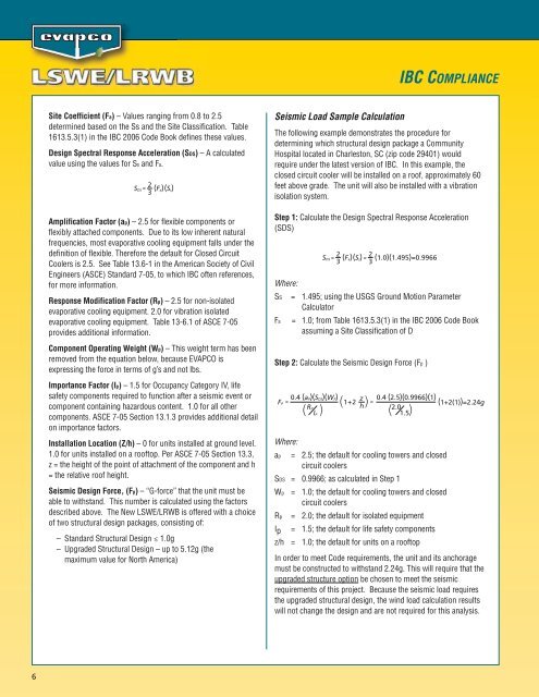
Site Coefficient (Fa) – Values ranging from 0.8 to 2.5<br />
determined based on the Ss and the Site Classification. Table<br />
1613.5.3(1) in the IBC 2006 Code Book defines these values.<br />
Design Spectral Response Acceleration (SDS) – A calculated<br />
value using the values for Ss and Fa.<br />
SDS<br />
= 2<br />
3<br />
(Fa)(Ss)<br />
Amplification Factor (ap) – 2.5 for flexible <strong>com</strong>ponents or<br />
flexibly attached <strong>com</strong>ponents. Due to its low inherent natural<br />
frequencies, most evaporative cooling equipment falls under the<br />
definition of flexible. Therefore the default for Closed Circuit<br />
Coolers is 2.5. See Table 13.6-1 in the American Society of Civil<br />
Engineers (ASCE) Standard 7-05, to which IBC often references,<br />
for more information.<br />
Response Modification Factor (Rp) – 2.5 for non-isolated<br />
evaporative cooling equipment. 2.0 for vibration isolated<br />
evaporative cooling equipment. Table 13-6.1 of ASCE 7-05<br />
provides additional information.<br />
Component Operating Weight (Wp) – This weight term has been<br />
removed from the equation below, because <strong>EVAPCO</strong> is<br />
expressing the force in terms of g’s and not lbs.<br />
Importance Factor (Ip) – 1.5 for Occupancy Category IV, life<br />
safety <strong>com</strong>ponents required to function after a seismic event or<br />
<strong>com</strong>ponent containing hazardous content. 1.0 for all other<br />
<strong>com</strong>ponents. ASCE 7-05 Section 13.1.3 provides additional detail<br />
on importance factors.<br />
Installation Location (Z/h) – 0 for units installed at ground level.<br />
1.0 for units installed on a rooftop. Per ASCE 7-05 Section 13.3,<br />
z = the height of the point of attachment of the <strong>com</strong>ponent and h<br />
= the relative roof height.<br />
Seismic Design Force, (Fp) – “G-force” that the unit must be<br />
able to withstand. This number is calculated using the factors<br />
described above. The New <strong>LSWE</strong>/LRWB is offered with a choice<br />
of two structural design packages, consisting of:<br />
– Standard Structural Design ≤ 1.0g<br />
– Upgraded Structural Design – up to 5.12g (the<br />
maximum value for North America)<br />
Seismic Load Sample Calculation<br />
The following example demonstrates the procedure for<br />
determining which structural design package a Community<br />
Hospital located in Charleston, SC (zip code 29401) would<br />
require under the latest version of IBC. In this example, the<br />
closed circuit cooler will be installed on a roof, approximately 60<br />
feet above grade. The unit will also be installed with a vibration<br />
isolation system.<br />
Step 1: Calculate the Design Spectral Response Acceleration<br />
(SDS)<br />
Where:<br />
SS = 1.495; using the USGS Ground Motion Parameter<br />
Calculator<br />
Fa = 1.0; from Table 1613.5.3(1) in the IBC 2006 Code Book<br />
assuming a Site Classification of D<br />
Step 2: Calculate the Seismic Design Force (Fp )<br />
Where:<br />
SDS<br />
= 2<br />
3<br />
(Fa)(Ss)<br />
= 2<br />
3<br />
1+2 z<br />
0.4 (aP)(SDS)(WP)<br />
( )<br />
FP = =<br />
RP<br />
h<br />
( IP )<br />
IBC COMPLIANCE<br />
(1.0)(1.495)=0.9966<br />
0.4 (2.5)(0.9966)(1)<br />
2.0 1.5<br />
( )<br />
ap = 2.5; the default for cooling towers and closed<br />
circuit coolers<br />
SDS = 0.9966; as calculated in Step 1<br />
Wp = 1.0; the default for cooling towers and closed<br />
circuit coolers<br />
Rp = 2.0; the default for isolated equipment<br />
Ip = 1.5; the default for life safety <strong>com</strong>ponents<br />
z/h = 1.0; the default for units on a rooftop<br />
(1+2(1))=2.24g<br />
In order to meet Code requirements, the unit and its anchorage<br />
must be constructed to withstand 2.24g. This will require that the<br />
upgraded structure option be chosen to meet the seismic<br />
requirements of this project. Because the seismic load requires<br />
the upgraded structural design, the wind load calculation results<br />
will not change the design and are not required for this analysis.


