LSWE Product Catalog - EVAPCO.com
LSWE Product Catalog - EVAPCO.com
LSWE Product Catalog - EVAPCO.com

Create successful ePaper yourself
Turn your PDF publications into a flip-book with our unique Google optimized e-Paper software.
†<br />
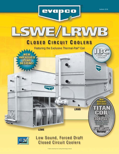
<strong>LSWE</strong><br />
† Mark owned by the Cooling Technology Institute<br />
LRWB<br />
Bulletin 251B
2<br />
Since its founding in 1976, <strong>EVAPCO</strong>, Incorporated<br />
has be<strong>com</strong>e an industry leader in the engineering<br />
and manufacturing of quality heat transfer products<br />
around the world. <strong>EVAPCO</strong>’s mission is to provide first<br />
class service and quality products for the following<br />
markets:<br />
� Industrial Refrigeration<br />
� Commercial HVAC<br />
� Industrial Process<br />
� Power<br />
<strong>EVAPCO</strong>’s powerful <strong>com</strong>bination of financial strength and<br />
technical expertise has established the <strong>com</strong>pany as a<br />
recognized manufacturer of market-leading products on<br />
a worldwide basis. <strong>EVAPCO</strong> is also recognized for the<br />
superior technology of their environmentally friendly<br />
product innovations in sound reduction and water<br />
management.<br />
<strong>EVAPCO</strong> is an employee owned <strong>com</strong>pany with a strong<br />
emphasis on research & development and modern<br />
manufacturing plants. <strong>EVAPCO</strong> has earned a reputation<br />
for technological innovation and superior product quality<br />
by featuring products that are designed to offer these<br />
operating advantages:<br />
� Higher System Efficiency<br />
� Environmentally Friendly<br />
� Lower Annual Operating Costs<br />
� Reliable, Simple Operation and<br />
Maintenance<br />
With an ongoing <strong>com</strong>mitment to Research & Development<br />
programs, <strong>EVAPCO</strong> provides the most advanced<br />
products in the industry – Technology for the Future,<br />
Available Today!<br />
<strong>EVAPCO</strong> products are manufactured in 17 locations in 8<br />
countries around the world and supplied through a sales<br />
network consisting of over 170 offices.<br />
©2010 <strong>EVAPCO</strong>, Inc.<br />
Design and Construction Features<br />
The <strong>LSWE</strong> and LRWB units are a result of <strong>EVAPCO</strong>’s extensive experience<br />
in forced draft centrifugal fan designs. Both models are designed for easy<br />
maintenance and long, trouble free operation. These units are also designed<br />
†<br />
with IBC Compliant construction and Certified Performance. All<br />
features shown are available on all models.<br />
Exclusive<br />
Thermal-Pak ® Coil<br />
• Providing Maximum<br />
Efficiency Per Plan Area<br />
NEW!<br />
Easy Field Assembly<br />
• Ensures easy assembly and<br />
fewer fasteners<br />
• Incorporates self-guiding<br />
channels to guide the coil<br />
casing section into position<br />
improving the quality of the<br />
field seam<br />
Totally Enclosed<br />
Pump Motors<br />
• Helps assure long,<br />
trouble-free operation<br />
NEW!<br />
Clean Pan Design<br />
• Sloped design allows<br />
water to drain <strong>com</strong>pletely<br />
from cold water basin<br />
• Easier Removal of dirt<br />
and debris<br />
NEW!<br />
Drift Eliminators<br />
Located in Casing<br />
• Drift eliminators integrate<br />
with coil casing section for<br />
easy mounting of ductwork,<br />
discharge hood and<br />
attenuation<br />
G-235 Heavy Mill-Dip<br />
Galvanized Steel<br />
Construction<br />
(Stainless steel available<br />
as an affordable option)<br />
Totally Enclosed Fan Motors<br />
• Assures long life<br />
• All normal maintenance can be performed<br />
quickly from outside the unit<br />
• If required, motor may be easily removed<br />
NEW!<br />
• Motors are now located outboard on multi-motor<br />
units for even easier drive system access<br />
• Premium efficient inverter-ready motors are standard<br />
• 5 Year motor and drive warranty is standard<br />
† Mark owned by the Cooling Technology Institute
IBC Certification<br />
• Every unit has<br />
independent<br />
certification and<br />
<strong>com</strong>pliance<br />
with IBC<br />
Efficient Drift Eliminators<br />
• Advanced design limits maximum<br />
drift rate to 0.001% of circulated<br />
spray water rate<br />
• Corrosion resistant PVC for long life<br />
U.S. Patent # 6,315,804<br />
Easy to Service<br />
Motor & Drive System<br />
Zero Maintenance PVC Spray Distribution<br />
Header with ZMII ® Nozzles<br />
• Nozzles are threaded into header at proper orientation<br />
• Fixed position nozzles require zero maintenance<br />
• Large orifice nozzles prevent clogging<br />
• Threaded end caps for ease of cleaning<br />
• Belt tensioning and bearing lubrication can be<br />
performed from outside the unit<br />
• Locking mechanism can also be used as a<br />
wrench to adjust the belts (LRWB only)<br />
• Motor is fully accessible by removing one inlet screen<br />
• Split fan housings allow removal of all mechanical<br />
equipment through the end of the unit (LRWB only)<br />
† Mark owned by the Cooling Technology Institute<br />
Standard Stainless<br />
Steel Cold Water Basin<br />
• Eliminates the need for<br />
unreliable epoxy coatings<br />
CTI Certified<br />
Optional<br />
Featuring Thermal-Pak ® XT Construction<br />
The Premier Closed Circuit Cooler Coil in the<br />
HVAC industry! The Titan provides:<br />
• 304L SST Construction for Superior<br />
Corrosion Resistance<br />
• 5 Year Extended Coil Warranty –<br />
STANDARD!!<br />
• Proprietary Thermal-Pak ® XT elliptical tube<br />
design with elliptical return bends and<br />
extra tough construction<br />
Optional Pulse~Pure ®<br />
Water Treatment System<br />
All units are available with <strong>EVAPCO</strong>’s<br />
optional Pulse~Pure ® non-chemical water<br />
treatment system. The Pulse~Pure ®<br />
Water Treatment System utilizes pulsedpower<br />
technology to provide CHEMICAL<br />
FREE Water Treatment. <strong>EVAPCO</strong>’s<br />
Pulse~Pure ® system is an environmentally<br />
responsible alternative for treating water in<br />
evaporative cooled equipment. It does not<br />
release harmful by-products to the<br />
environment and eliminates chemicals<br />
<strong>com</strong>pletely from cooler drift and blowdown.<br />
The Pulse~Pure ® system delivers short,<br />
high-frequency bursts of low energy<br />
electromagnetic fields to the recirculating<br />
water in the <strong>LSWE</strong> and LRWB and will:<br />
• Control bacteria to levels well below<br />
traditional chemical water treatment<br />
• Control the formation of mineral scale<br />
• Save water by operating at higher cycles<br />
of concentration<br />
• Yield corrosion rates equivalent to<br />
chemical water treatment<br />
†<br />
U.S. Patent # 7,704,364<br />
3
4<br />
In its continuing <strong>com</strong>mitment to be the leaders in evaporative cooling equipment design and services, <strong>EVAPCO</strong>’s<br />
<strong>LSWE</strong> & LRWB Closed Circuit Coolers are now Independently Certified to withstand both Seismic and Wind Loads in<br />
ALL Geographic Locations and Installations in accordance with IBC 2006.<br />
What is IBC?<br />
International Building Code<br />
The International Building Code (IBC) is a <strong>com</strong>prehensive set of<br />
regulations addressing both the structural design and the<br />
installation requirements for building systems – including<br />
HVAC and industrial refrigeration equipment. The IBC is<br />
intended to replace BOCA’s The National Building Code, ICBO’s<br />
Uniform Building Code and SBCCI’s Standard Building Code.<br />
Compared to previous building codes that considered only the<br />
building structure and <strong>com</strong>ponent anchorage, the requirements<br />
contained within the IBC address anchorage, structural<br />
integrity, and the operational capability of a <strong>com</strong>ponent<br />
following either a seismic or wind load event. Simply stated,<br />
the IBC code provisions require that evaporative cooling<br />
equipment, and all other <strong>com</strong>ponents permanently installed<br />
on a structure, must be designed to meet the same seismic<br />
and wind load forces as the building to which they are<br />
attached.<br />
How Does IBC 2006 Apply to Closed Circuit<br />
Coolers?<br />
Based on the project zip code and site design factors,<br />
calculations are made to determine the equivalent seismic “g<br />
force” and wind load (in pounds per square foot – psf) on the<br />
unit. The closed circuit cooler must be designed to withstand the<br />
greater of either the seismic or wind load.<br />
The New <strong>LSWE</strong> and LRWB are offered with a choice of TWO<br />
structural design packages:<br />
• Standard Structural Design – For projects with<br />
≤ 1.0g seismic or 145 psf wind loads<br />
• Upgraded Structural Design – Required for projects with ><br />
1.0g seismic or 145 psf max wind loads<br />
More than 80% of the United States has design criteria resulting<br />
in a seismic design force of 1.0g or below. These sites will be<br />
provided with the standard <strong>LSWE</strong> or LRWB structural design.<br />
An upgraded structural design is available for installations with<br />
design criteria resulting in “g forces” greater than 1.0g. The<br />
highest “g force” location in North America is 5.12g. The<br />
highest wind load shown on the maps is 170 mph, which is<br />
approximately equal to 145 psf velocity pressure. Therefore,<br />
the upgraded structural design package option for the New<br />
<strong>LSWE</strong> and LRWB is designed for 5.12g and 145 psf making it<br />
applicable to ALL building locations in North America.<br />
Seismic Design<br />
The attached chart from the US Geological Survey Website<br />
(http://www.usgs.gov/) shows the potential seismic activity in the<br />
United States. Buildings constructed in the red, orange and yellow<br />
areas of the map may require the upgraded <strong>LSWE</strong> or LRWB<br />
construction design based on the site seismic design factors and<br />
should be reviewed closely. Critical use facilities, such as<br />
hospitals, are also more likely to require the upgraded design.<br />
Map courtesy US Geological Survey website<br />
IBC COMPLIANCE<br />
Highest Hazard<br />
32+<br />
24-32<br />
16-24<br />
%g 8-16<br />
4-8<br />
2-4<br />
0-2<br />
Lowest Hazard<br />
The project architect or civil engineer is responsible for<br />
determining the seismic design factors to be used for the<br />
building design. A mechanical consulting engineer and/or<br />
design build contractor then applies these factors to a series of<br />
charts and graphs to determine the appropriate seismic design<br />
factors based on the location of the installation and ultimately<br />
the “importance” of the facility. The specific factors necessary<br />
for seismic design as well as a sample seismic calculation are<br />
shown on the next page.
IBC COMPLIANCE<br />
Wind Design<br />
The IBC 2006 code book includes a map of basic wind speed (3second<br />
gust) by contour lines. However, local regulations may be<br />
more stringent than these published speeds. The specific factors<br />
necessary for wind load as well as a sample wind load calculation<br />
are shown on Page 7.<br />
Whichever design force - seismic or wind - is more severe for<br />
the building, governs the design of the building and all<br />
attached equipment.<br />
Wind Load Map Courtesy IBC 2006 Text –<br />
See full-sized map for location specific values<br />
Design Implementation<br />
<strong>EVAPCO</strong> applies the given seismic and wind load information<br />
provided by the mechanical consulting engineer to determine<br />
the equipment design necessary to meet IBC requirements.<br />
This process ensures that the mechanical equipment and its<br />
<strong>com</strong>ponents are <strong>com</strong>pliant per the provisions of the IBC as<br />
given in the plans and specifications for the project. For design<br />
build projects, <strong>EVAPCO</strong> is equipped to look up the information<br />
and submit the resulting loads for approval.<br />
Independent Certification<br />
Per the most recent edition of the code, the <strong>EVAPCO</strong> <strong>com</strong>pliance<br />
process included an exhaustive analysis by an independent approval<br />
agency. As required<br />
by the International<br />
Building Code,<br />
<strong>EVAPCO</strong> supplies a certificate<br />
of <strong>com</strong>pliance<br />
as part of its submittal<br />
documents. The certificate<br />
of <strong>com</strong>pliance<br />
demonstrates that the<br />
equipment has been in-<br />
Certificate of Compliance<br />
LSTE, LPT, PMTQ Cooling Towers<br />
PMWQ, <strong>LSWE</strong>, LRWB Closed Circuit Coolers<br />
PMC-E, LSC-E and LRC Evaporative Condensers<br />
Are certified to meet or exceed the Seismic and Wind Load Provisions<br />
set forth in the applicable building codes for this project.<br />
These products have been manufactured following all<br />
applicable quality assurance programs.<br />
Applicable Building Codes:<br />
IBC 2006<br />
ASCE-7<br />
NFPA 5000<br />
Referenced Report:<br />
VMA-43387<br />
Approval Agency:<br />
VMC Seismic Consulting Group<br />
<strong>EVAPCO</strong>...Specialists in Heat Transfer <strong>Product</strong>s and Services. FD IBC COC 001<br />
dependently tested and analyzed in accordance with the IBC seismic<br />
and wind load requirements. Evapco has worked closely with<br />
the independent approval agency to <strong>com</strong>plete the independent<br />
equipment testing and analysis.<br />
If the seismic “g force” and wind “psf” load requirements for<br />
the project site are known, <strong>EVAPCO</strong>’s online equipment<br />
selection software, iES, will allow you to choose the required<br />
structural design package – either standard construction or<br />
upgraded construction.<br />
If the project requirements are unknown, the following<br />
calculations must be <strong>com</strong>pleted.<br />
For further questions regarding IBC <strong>com</strong>pliance, please contact<br />
your local <strong>EVAPCO</strong> Representative or visit www.evapco.<strong>com</strong>.<br />
When using the <strong>EVAPCO</strong> selection software to make a<br />
selection, these calculations are already incorporated into the<br />
selection process. Simply enter the required seismic factors<br />
and the Seismic Design Force and Wind Load will be calculated<br />
automatically!!<br />
Seismic Load Calculations<br />
The data required to calculate the seismic load are:<br />
Occupancy Category – I, II, III or IV depending on the nature of<br />
the building occupancy. Table 1604.5 in the IBC 2006 Code Book<br />
defines each of the four categories in detail. In summary the four<br />
categories are:<br />
• Category I - structures that represent a low hazard<br />
to human life in the event of a failure.<br />
• Category III - structures that represent a substantial<br />
hazard to human life in the event of a failure.<br />
• Category IV - structures designated as essential<br />
facilities.<br />
• Category II - any structures not listed in I, III or IV.<br />
Site Classification – A, B, C, D, E or F based on the types of soil<br />
and their engineering properties. Table 1613.5.2 in the IBC 2006<br />
Code Book defines each of the categories in detail. IBC specifies<br />
site class “D” when soil properties are unknown.<br />
Maximum Spectral Response Acceleration (Ss) – Numerical<br />
value found using the U.S. Geological (USGS) data based on the<br />
Zip Code of the project. This data point can be determined<br />
using the Ground Motion Parameter Calculator at<br />
http://www.usgs.gov/. Note the calculator assumes a site<br />
classification of B for the 0.2 second maximum Ss. The site<br />
coefficient (Fa), defined below, will correct for the actual site<br />
classification.<br />
5
6<br />
Site Coefficient (Fa) – Values ranging from 0.8 to 2.5<br />
determined based on the Ss and the Site Classification. Table<br />
1613.5.3(1) in the IBC 2006 Code Book defines these values.<br />
Design Spectral Response Acceleration (SDS) – A calculated<br />
value using the values for Ss and Fa.<br />
SDS<br />
= 2<br />
3<br />
(Fa)(Ss)<br />
Amplification Factor (ap) – 2.5 for flexible <strong>com</strong>ponents or<br />
flexibly attached <strong>com</strong>ponents. Due to its low inherent natural<br />
frequencies, most evaporative cooling equipment falls under the<br />
definition of flexible. Therefore the default for Closed Circuit<br />
Coolers is 2.5. See Table 13.6-1 in the American Society of Civil<br />
Engineers (ASCE) Standard 7-05, to which IBC often references,<br />
for more information.<br />
Response Modification Factor (Rp) – 2.5 for non-isolated<br />
evaporative cooling equipment. 2.0 for vibration isolated<br />
evaporative cooling equipment. Table 13-6.1 of ASCE 7-05<br />
provides additional information.<br />
Component Operating Weight (Wp) – This weight term has been<br />
removed from the equation below, because <strong>EVAPCO</strong> is<br />
expressing the force in terms of g’s and not lbs.<br />
Importance Factor (Ip) – 1.5 for Occupancy Category IV, life<br />
safety <strong>com</strong>ponents required to function after a seismic event or<br />
<strong>com</strong>ponent containing hazardous content. 1.0 for all other<br />
<strong>com</strong>ponents. ASCE 7-05 Section 13.1.3 provides additional detail<br />
on importance factors.<br />
Installation Location (Z/h) – 0 for units installed at ground level.<br />
1.0 for units installed on a rooftop. Per ASCE 7-05 Section 13.3,<br />
z = the height of the point of attachment of the <strong>com</strong>ponent and h<br />
= the relative roof height.<br />
Seismic Design Force, (Fp) – “G-force” that the unit must be<br />
able to withstand. This number is calculated using the factors<br />
described above. The New <strong>LSWE</strong>/LRWB is offered with a choice<br />
of two structural design packages, consisting of:<br />
– Standard Structural Design ≤ 1.0g<br />
– Upgraded Structural Design – up to 5.12g (the<br />
maximum value for North America)<br />
Seismic Load Sample Calculation<br />
The following example demonstrates the procedure for<br />
determining which structural design package a Community<br />
Hospital located in Charleston, SC (zip code 29401) would<br />
require under the latest version of IBC. In this example, the<br />
closed circuit cooler will be installed on a roof, approximately 60<br />
feet above grade. The unit will also be installed with a vibration<br />
isolation system.<br />
Step 1: Calculate the Design Spectral Response Acceleration<br />
(SDS)<br />
Where:<br />
SS = 1.495; using the USGS Ground Motion Parameter<br />
Calculator<br />
Fa = 1.0; from Table 1613.5.3(1) in the IBC 2006 Code Book<br />
assuming a Site Classification of D<br />
Step 2: Calculate the Seismic Design Force (Fp )<br />
Where:<br />
SDS<br />
= 2<br />
3<br />
(Fa)(Ss)<br />
= 2<br />
3<br />
1+2 z<br />
0.4 (aP)(SDS)(WP)<br />
( )<br />
FP = =<br />
RP<br />
h<br />
( IP )<br />
IBC COMPLIANCE<br />
(1.0)(1.495)=0.9966<br />
0.4 (2.5)(0.9966)(1)<br />
2.0 1.5<br />
( )<br />
ap = 2.5; the default for cooling towers and closed<br />
circuit coolers<br />
SDS = 0.9966; as calculated in Step 1<br />
Wp = 1.0; the default for cooling towers and closed<br />
circuit coolers<br />
Rp = 2.0; the default for isolated equipment<br />
Ip = 1.5; the default for life safety <strong>com</strong>ponents<br />
z/h = 1.0; the default for units on a rooftop<br />
(1+2(1))=2.24g<br />
In order to meet Code requirements, the unit and its anchorage<br />
must be constructed to withstand 2.24g. This will require that the<br />
upgraded structure option be chosen to meet the seismic<br />
requirements of this project. Because the seismic load requires<br />
the upgraded structural design, the wind load calculation results<br />
will not change the design and are not required for this analysis.
IBC COMPLIANCE<br />
Wind Load Calculations<br />
Note, both the standard construction and the upgraded<br />
construction on the <strong>LSWE</strong> and LRWB Closed Circuit Coolers are<br />
designed to meet a wind load of 145 psf. Therefore, the<br />
following details are provided for informational purposes only.<br />
The data required to calculate the wind load are:<br />
Basic Wind Speed (V) – Numerical value, in miles per hour<br />
(mph) found in ASCE 7-05 Figures 6-1 (A,B,C).<br />
Wind Directionality Factor (Kd) – 0.85 for building <strong>com</strong>ponents<br />
and cladding. Table 6-4 of ASCE 7-05 provides additional<br />
information.<br />
Occupancy Category – I, II, III or IV depending on the nature of<br />
the building occupancy. Table 1604.5 in the IBC 2006 Code<br />
Book defines each of the categories in detail. This is the same<br />
Occupancy Category used in Seismic calculations.<br />
Importance Factor (I) – Numerical value between 0.77 and 1.15<br />
based on the Basic Wind Speed and the Occupancy Category.<br />
These values are found in Table 6-1 of ASCE 7-05.<br />
Exposure Category – B, C or D as defined in Section 6.5.6.3 of<br />
ASCE 7-05.<br />
Component Elevation (z) – The anchorage height of the unit in<br />
feet.<br />
Nominal Height of the Atmospheric Boundary Layer (zg) -<br />
Numerical value based on Exposure Category. These values are<br />
found in Table 6-2 of ASCE 7-05.<br />
3 second Gust-Speed power Law Exponent (α) - Numerical<br />
value based on Exposure Category. These values are found in<br />
Table 6-2 of ASCE 7-05.<br />
Velocity Pressure Exposure Coefficient (Kz) – A calculated value<br />
using the values for zg and α.<br />
KZ = 2.01<br />
z<br />
( zg)<br />
2<br />
( a )<br />
Topographic Factor (Kzt) – 1.0 default when topographic effects<br />
are not a factor. ASCE 7-05 Section 6.5.7 provides additional<br />
detail on topographic factors.<br />
Velocity Pressure (qz) – This number in pounds per square foot<br />
(psf) is calculated using the factors described above. The New<br />
<strong>LSWE</strong> and LRWB are offered with a choice of two structural<br />
design packages, consisting of:<br />
– Standard Design and Upgraded Structural Design –<br />
both up to 145 psf (the maximum value for North<br />
America)<br />
Wind Load Sample Calculation<br />
The following example demonstrates the procedure to determine<br />
which structural design package a Condominium Building located<br />
in Miami, FL (zip code 33101) would require under the latest<br />
version of IBC. In this example, the closed circuit cooler will be<br />
installed on the top of the 60 foot tall building.<br />
Step 1: Calculate the Exposure Category Coefficient (Kz)<br />
Where:<br />
z = 60; Installation Height<br />
zg = 700; from ASCE 7-05 Table 2 using an Exposure<br />
Category of D.<br />
α = 11.5; from ASCE 7-05 Table 2 using an Exposure<br />
Category of D.<br />
Step 2: Calculate the Velocity Pressure (qz)<br />
Where:<br />
( a )<br />
qz = 0.00256(Kz)(Kzt)(Kd)(V 2 )(I) =<br />
0.00256(1.31)(1.0)(0.85)(145 2 )(1.0) = 59.93psf<br />
Kz = 1.31; as calculated above.<br />
( )<br />
( 11.5)<br />
KZ = 2 2<br />
z<br />
60<br />
2.01<br />
= ( zg)<br />
2.01 =<br />
700<br />
1.31<br />
Kzt = 1.0; default when topographic effects are not a factor.<br />
Kd = 0.85; default for building <strong>com</strong>ponents and cladding.<br />
V = 145; wind speed from ASCE 7-05 Figure 6-1.<br />
I = 1.0; Based on an Occupancy Category of II.<br />
In order to meet Code requirements, the unit and its attachments<br />
must be designed and constructed to withstand 59.93 psf.<br />
Because the wind load does not dictate the closed circuit cooler<br />
design, the seismic load calculation must also be <strong>com</strong>pleted to<br />
determine if the results will change the unit design.<br />
7
8<br />
Principle of Operation<br />
The process fluid is circulated through the coil of the closed<br />
circuit cooler. Heat from the process fluid is dissipated through<br />
the coil tubes to the water cascading downward over the tubes.<br />
Simultaneously air is blown through the unit by the fans and<br />
travels upward over the coil opposite the water flow. A small<br />
portion of the water is evaporated which removes the heat. The<br />
warm moist air is forced to the top of the closed circuit cooler<br />
by the fan and is discharged to the atmosphere. The remaining<br />
water falls to the sump at the bottom of the cooler where it is<br />
recirculated by the pump up through the water distribution<br />
system and back down over the coils.<br />
Water<br />
Distribution<br />
System<br />
Coil<br />
Fan &<br />
Fan Motors<br />
Drift<br />
Eliminators<br />
Discharge<br />
Air<br />
Example of an <strong>LSWE</strong><br />
<strong>EVAPCO</strong>AT Corrosion Protection System:<br />
G-235 Hot-Dip Galvanized Steel Construction<br />
Fluid In<br />
Fluid Out<br />
Entering<br />
Air<br />
The standard material of construction for evaporative cooling<br />
equipment for many years has been hot-dip galvanized steel.<br />
The purpose of galvanizing is to protect the base metal from<br />
corrosion, and the thickness of the galvanized layer directly<br />
affects the equipment life.<br />
<strong>EVAPCO</strong> has been instrumental in the development of corrosion<br />
protection technology and was the first manufacturer to use<br />
G-235 galvanized steel construction. The G-235 designation<br />
equates to a minimum of 2.35 ounces of zinc per square foot of<br />
surface area.<br />
The <strong>EVAPCO</strong>AT Corrosion Protection System is the<br />
heaviest galvanized coating available for extended<br />
corrosion protection eliminating the need for costly,<br />
unreliable epoxy paint finishes.<br />
Stainless Steel Material Options<br />
The LRWB is standard with a stainless steel cold water basin.<br />
Optional upgrades to stainless steel water touch basins, stainless<br />
steel water touch units and all stainless steel construction<br />
are also available on the LRWB.<br />
The <strong>LSWE</strong> is available with optional stainless steel cold water<br />
basins, water touch basins, water touch units and all stainless<br />
steel construction.<br />
For more information on these stainless steel options, see your<br />
local Evapco sales representative<br />
Cooling Coil<br />
Evapco Closed Circuit Coolers utilize <strong>EVAPCO</strong>’s proprietary<br />
Thermal-Pak ® coil design which assures greater operating<br />
efficiency. The elliptical tube design allows for closer tube<br />
spacing, resulting in greater surface area per plan area than<br />
round-tube coil designs. In addition, the Thermal-Pak ® design<br />
has lower resistance to airflow and also permits greater water<br />
loading, making the Thermal-Pak ® coil the most effective<br />
design available.<br />
Thermal-Pak ® Coil by <strong>EVAPCO</strong><br />
Round Tube Coil by Others<br />
DESIGN FEATURES<br />
The coils are manufactured from high quality steel tubing following<br />
the most stringent quality control procedures. Each circuit is<br />
inspected to ensure the material quality and then tested before<br />
being assembled into a coil. Finally, the assembled coil is pneumatically<br />
tested at 400 psig under water to ensure it is leak free.<br />
To protect the coil against corrosion, it is placed in a heavy steel<br />
frame and then the entire assembly is dipped in molten zinc<br />
(hot-dip galvanized) at a temperature of approximately 800°F.<br />
Note: Closed circuit coolers should only be used on sealed,<br />
pressurized systems. Continual aeration of the water in an open<br />
system can cause corrosion inside the tubes of the cooler leading to<br />
premature failure.
DESIGN FEATURES<br />
Stainless Steel Coil Option<br />
NOW Evapco offers the optional .<br />
Constructed with type 304L Stainless Steel, the TITAN COIL is<br />
manufactured using Evapco’s proprietary elliptical tube Thermal<br />
Pak ® design upgraded to Xtra Tough construction featuring: Xtra<br />
Durability, Xtra Corrosion Resistance, and an Xtra long 5 YEAR<br />
Coil Warranty as standard.<br />
Thermal-Pak ® Coil<br />
Maintenance Free ZMII ® Spray Nozzle<br />
Water Distribution System<br />
<strong>EVAPCO</strong>’S Zero Maintenance ZMII ®<br />
Spray Nozzle remains clog-free while<br />
providing even and constant water<br />
distribution for reliable, scale-free<br />
evaporative cooling under all operating<br />
conditions.<br />
The heavy duty nylon ZMII ® Spray nozzles<br />
have a 1-5/16” diameter opening and<br />
a 1-1/2” splash plate clearance. Furthermore,<br />
the fixed position ZMII ® nozzles<br />
are mounted in corrosion-free PVC water<br />
distribution pipes that have threaded end<br />
caps. Together, these elements <strong>com</strong>bine<br />
to provide unequaled coil coverage and<br />
scale prevention, and make the industry’s<br />
best performing non-corrosive, maintenance-free<br />
water distribution system.<br />
ZMII ® Nozzle<br />
Efficient Drift Eliminators<br />
The <strong>LSWE</strong> & LRWB are provided with an efficient drift eliminator<br />
system that effectively reduces entrained water droplets from the<br />
air discharge to less than 0.001% of the spray water flow rate.<br />
The eliminators are constructed of non-corrosive PVC with a<br />
multi-pass design for maximum drift reduction. They are<br />
assembled in modular sections for easy removal and access to<br />
the water distribution system.<br />
In addition to reducing drift, the eliminators also function as<br />
effective debris screens which protect the spray system from<br />
sunlight and debris.<br />
<strong>LSWE</strong> and LRWB Drift Eliminator<br />
Drift Eliminators Removed for Coil Inspection<br />
U.S. Patent # 6,315,804<br />
9
10<br />
Fan Motor Mount<br />
TEFC fan motors are mounted in a convienent open area for<br />
ease of belt tensioning, motor lubrication and electrical<br />
connection. The motor base is designed for easy adjustment<br />
and to be locked into position to maintain proper belt tension.<br />
Example <strong>LSWE</strong> Fan Motor Mount LRWB Fan Motor Mount<br />
(shown with optional pony motor)<br />
Fan Access-Split Housing<br />
Mechanical Drive System Access<br />
Another unique feature of the<br />
LRWB Closed Circuit Cooler is the<br />
split fan housing. The split fan<br />
housing on the LRWB allows<br />
quick removal of the fans from the<br />
front end of the unit. This feature<br />
allows fan removal when units are<br />
placed side by side where space is<br />
minimal.<br />
The <strong>LSWE</strong> and LRWB mechanical drive systems are easy to<br />
maintain. Bearing lubrication and belt adjustment can be<br />
performed from outside the unit. There is no need to remove<br />
fan screens to maintain important drive <strong>com</strong>ponents. In<br />
addition, the locking mechanism used to maintain belt tension<br />
can also work as a wrench to adjust the belt.<br />
Centrifugal Fan Assembly<br />
Fans on <strong>LSWE</strong> and LRWB<br />
Closed Circuit Coolers are of the<br />
forward curved centrifugal<br />
design with hot-dip galvanized<br />
steel construction. All fans are<br />
statically and dynamically<br />
balanced and are mounted in a<br />
hot-dip galvanized steel housing.<br />
Basin Access<br />
The <strong>LSWE</strong> drain pan is designed to improve maintenance<br />
access and make it easier for operating technicians to clean.<br />
The bottom of the pan is sloped to the unit drain to ensure that<br />
the basin will <strong>com</strong>pletely drain and allow sediment and debris<br />
that may collect in the basin to be easily flushed from the unit.<br />
The design helps to prevent buildup of sedimentary deposits,<br />
biological films and standing water.<br />
Large circular access doors are<br />
provided to allow entry into the<br />
basin. All float valve and strainer<br />
assemblies are located near the<br />
door for easy adjustment and<br />
cleaning. The sump is designed<br />
to catch the dirt accumulated.<br />
This can be flushed out simply<br />
with a hose. The stainless steel<br />
strainers may be easily removed<br />
for periodic cleaning.<br />
Capacity Control<br />
DESIGN FEATURES<br />
All <strong>LSWE</strong> and LRWB models <strong>com</strong>e standard with premium efficient,<br />
inverter capable fan motors that can be used with variable<br />
frequency drive (VFD) systems for precise capacity control. VFD<br />
systems can control the speed of a fan motor by modulating the<br />
voltage and frequency of the motor input electrical signal. When<br />
connected to a building automation system a VFD can receive<br />
signals varying fan speeds to meet demand loads. This popular<br />
method of capacity control can yield significant energy savings.<br />
Evapco offers two-speed fan motors as an option for alternative<br />
capacity control. In periods of lightened loads or reduced wet<br />
bulb temperatures the fans can operate at low speed providing<br />
about 60% of full speed capacity yet consuming only about 15%<br />
of full speed power. In addition to the energy savings the sound<br />
levels of the unit can be greatly reduced by operating at low<br />
speed. These motors do not require the use of VFD systems<br />
however they can only operate at two speeds: full or low.<br />
Pony motors are available as another capacity control method.<br />
Pony motors are smaller fan motors for use in times of reduced<br />
loading. The pony motor is typically 1/4 of the Hp of the primary<br />
motor and can significantly reduce energy requirements.
SPECIFIC DESIGN FEATURES<br />
LRWB Reduced Height and Maintenance<br />
Accessibility<br />
The LRWB has been designed to satisfy installation<br />
requirements where height limits must be observed. The lower<br />
profile design of the LRWB does not, however, sacrifice<br />
maintenance accessibility for reduced height. Its unique casing<br />
design allows the water distribution system, cold water basin,<br />
fan section and other unit <strong>com</strong>ponents to be easily maintained.<br />
Small, light-weight sections of the drift eliminators can be easily<br />
removed to access the water distribution system. A large<br />
circular access door is located on the side of the cold water<br />
basin to allow adjustment of the float assembly, removal of the<br />
stainless steel strainers and cleaning of the basin. The fan motor<br />
and drive system are located at one end of the unit and are<br />
<strong>com</strong>pletely accessible by removing the inlet screens. Routine<br />
bearing lubrication and belt tensioning can be performed from<br />
the exterior of the unit without removing the inlet screens.<br />
Low Installed Costs<br />
The <strong>com</strong>pact, unitary design of the LRWB closed circuit cooler<br />
allows it to be shipped <strong>com</strong>pletely assembled. This results in<br />
lower transportation costs and no assembly requirements at the<br />
job site. Note: Options such as sound attenuation and discharge<br />
hoods will require additional lifts and some minor assembly.<br />
M<br />
H =<br />
6’ 1-1/4” to 9’ 3-3/4”<br />
Transport of a Pre-Assembled Unit<br />
Since the LRWB ships fully assembled, it is ideal for<br />
truck-mounted applications, for remote sites or temporary<br />
installations.<br />
Stainless Steel Cold Water Basin–Standard<br />
The LRWB is standard with a stainless steel cold water basin.<br />
Optional upgrades to stainless steel water touch basins,<br />
stainless steel water touch units and all stainless steel<br />
construction are also available on the LRWB.<br />
Integral Fan Enclosure for Lower Sound<br />
The LRWB <strong>com</strong>es standard with an integral fan enclosure that<br />
reduces sound levels by 2 dB. This 3-sided enclosure also<br />
protects the fan and drive system<br />
for longer equipment life.<br />
Fan Enclosure<br />
M<br />
11
12<br />
Application Versatility<br />
Centrifugal units are re<strong>com</strong>mended for a wide range of installations. They are quiet, can easily be hidden, and the increase in fan HP<br />
over propeller fan units is generally not significant in the small size range. They are also excellent for installations where sound is<br />
sensitive, such as residential neighborhoods, and when the unit must handle external static pressure.<br />
Very Quiet Operation<br />
Centrifugal fan units operate at low sound levels which make this<br />
design preferred for installations with external static pressure<br />
where noise is a concern. Additionally, since the sound from the<br />
fans is directional, single sided air entry models can be turned<br />
away from critical areas avoiding a sound problem. When even<br />
quieter operation is necessary, centrifugal fan models can be<br />
equipped with optional sound attenuation packages. See the<br />
Sound Reducing Options section of this catalog or consult the<br />
factory for details.<br />
In addition, the LRWB features a specially engineered fan<br />
enclosure and drive system that is designed to offer very quiet<br />
operation without the high cost of external attenuation packages.<br />
The LRWB fan system was developed through hundreds of hours<br />
of laboratory tests resulting in the lowest standardized sound<br />
levels available in the industry. In fact, the sound level of the<br />
LRWB on average is 2 dBA quieter than <strong>com</strong>petitors’ similar<br />
models.<br />
Indoor Installation<br />
<strong>LSWE</strong> Unit LRWB Unit<br />
All <strong>LSWE</strong> and LRWB Closed Circuit Coolers can be installed<br />
indoors where they normally require ductwork to and from the<br />
unit. The design of the ductwork should be symmetrical to<br />
provide even air distribution across both intake and discharge<br />
openings. Guidelines for Ducted Applications:<br />
1) The static pressure loss imposed by the ductwork must<br />
not exceed 1/2”. The fan motor size must be increased for<br />
ESP up to 1/2”.<br />
2) For ducted installations, the solid bottom panel option must<br />
be ordered. On the LRWB blank off plates will also be<br />
provided in lieu of the side air inlet screens with this option.<br />
3) NOTE: Access Doors must be located in the ductwork for<br />
service to the fan drive <strong>com</strong>ponents and water distribution<br />
system.<br />
Drawings are available showing re<strong>com</strong>mended ductwork<br />
connections. See <strong>EVAPCO</strong>’s Layout Guidelines for additional<br />
information.<br />
ACCESS DOOR<br />
APPLICATION<br />
ACCESS<br />
DOOR
PRODUCT APPLICATIONS<br />
Design<br />
<strong>EVAPCO</strong> Closed Circuit Coolers are of heavy-duty construction<br />
and designed for long trouble-free operation. Proper equipment<br />
selection, installation and maintenance is, however, necessary to<br />
ensure full unit performance. Some of the major considerations<br />
in the application of a cooler are presented below. For additional<br />
information, contact the factory.<br />
Air Circulation<br />
It is important that proper air circulation be provided. The best<br />
location is on an unobstructed roof top or on ground level away<br />
from walls and other barriers. Those closed circuit coolers located<br />
in wells, enclosures or adjacent to high walls must be properly<br />
located to avoid the problems associated with recirculation.<br />
Recirculation raises the wet bulb temperature of the entering air<br />
causing the water temperature to rise above the design. For<br />
these cases, the discharge of the unit should be located at a<br />
height even with the adjacent wall, thereby reducing the chance<br />
of recirculation. For additional information, see the <strong>EVAPCO</strong><br />
Equipment Layout Manual.<br />
Good engineering practice dictates that the closed circuit cooler<br />
discharge air not be directed or located close to or in the vicinity<br />
of building air intakes.<br />
Piping<br />
Cooler piping should be designed and installed in accordance<br />
with generally accepted engineering practices. The piping layout<br />
should be symmetrical on multiple unit systems, and sized for a<br />
reasonably low water velocity and pressure drop.<br />
The standard closed circuit cooler is re<strong>com</strong>mended only on a<br />
closed, pressurized system. The piping system should include an<br />
expansion tank to allow for fluid expansion and purging air from<br />
the system.<br />
Note: Closed Circuit Coolers should never be used on an open<br />
type system. An open type system with a cooler may result in<br />
premature coil failure.<br />
The piping system should be designed to permit <strong>com</strong>plete<br />
drainage of the heat exchanger coil. This will require a vacuum<br />
breaker or air vent to be installed at the high point and a drain<br />
valve installed at the low point of the piping system. Both must<br />
be adequately sized.<br />
All piping should be securely anchored by properly designed<br />
hangers and supports. No external loads should be placed upon<br />
the cooler connections, nor should any of the pipe supports be<br />
anchored to the cooler framework.<br />
Recirculating Water Quality<br />
Proper water treatment is an essential part of the maintenance<br />
required for evaporative cooling equipment. A well designed and<br />
consistently implemented water treatment program will help to<br />
ensure efficient system operation while maximizing the<br />
equipment’s service life. A qualified water treatment <strong>com</strong>pany<br />
should design a site specific water treatment protocol based on<br />
equipment (including all metallurgies in the cooling system),<br />
location, makeup water quality, and usage.<br />
Bleed off<br />
Evaporative cooling equipment requires a bleed or blowdown<br />
line, located on the discharge side of the recirculating pump, to<br />
remove concentrated (cycled up) water from the system. Evapco<br />
re<strong>com</strong>mends an automated conductivity controller to maximize<br />
the water efficiency of your system. Based on re<strong>com</strong>mendations<br />
from your water treatment <strong>com</strong>pany, the conductivity controller<br />
should open and close a motorized ball or solenoid valve to<br />
maintain the conductivity of the recirculating water. If a manual<br />
valve is used to control the rate of bleed it should be set to<br />
maintain the conductivity of the recirculating water during<br />
periods of peak load at the maximum level re<strong>com</strong>mended by<br />
your water treatment <strong>com</strong>pany.<br />
Water Treatment<br />
The water treatment program prescribed for the given conditions<br />
must be <strong>com</strong>patible with the unit’s materials of construction,<br />
including any galvanized <strong>com</strong>ponents. The initial <strong>com</strong>missioning<br />
and passivation period is a critical time for maximizing the service<br />
life of galvanized equipment. Evapco re<strong>com</strong>mends that the site<br />
specific water treatment protocol includes a passivation<br />
procedure which details water chemistry, any necessary chemical<br />
addition, and visual inspections during the first six (6) to twelve<br />
(12) weeks of operation. During this passivation period,<br />
recirculating water pH should be maintained above 7.0 and below<br />
8.0 at all times. Batch feeding of chemicals is not re<strong>com</strong>mended.<br />
Control of Biological Contaminants<br />
Evaporative cooling equipment should be inspected regularly to<br />
ensure good microbiological control. Inspections should include<br />
both monitoring of microbial populations via culturing<br />
techniques and visual inspections for evidence of biofouling.<br />
Poor microbiological control can result in loss of heat transfer<br />
efficiency, increase corrosion potential, and increase the risk of<br />
pathogens such as those that cause Legionnaires’ disease. Your<br />
site specific water treatment protocol should include procedures<br />
for routine operation, startup after a shut-down period, and<br />
system lay-up, if applicable. If excessive microbiological<br />
contamination is detected, a more aggressive mechanical<br />
cleaning and/or water treatment program should be undertaken.<br />
13
14<br />
Freeze Protection<br />
If the units are installed in a cold climate and operated<br />
year-round, freeze protection must be provided for the heat<br />
exchanger coil in the unit as well as for the recirculating<br />
water system.<br />
Recirculating Water System Freeze<br />
Protection Options<br />
Remote Sump Configuration<br />
The surest way to protect the recirculating water system from<br />
freezing is with a remote sump. The remote sump should be located<br />
inside the building and below the unit. When a remote<br />
sump arrangement is selected, the spray pump is provided by<br />
others and installed at the remote sump. All water in the closed<br />
circuit cooler basin should drain to the remote sump when the<br />
spray pump cycles off.<br />
Hot Water Coils<br />
Pan coils are available as an alternate to using electric basin<br />
heaters or a remote sump. Constructed of galvanized pipe and<br />
installed in the closed circuit cooler basin, they are supplied<br />
without controls and are ready for piping to an external hot<br />
water source. Pan water heater controls should be interlocked<br />
with the water circulating pump to prevent their operation when<br />
the pump is energized.<br />
M<br />
FREEZE PROTECTION AND HEAT LOSS<br />
Basin Heater Package<br />
If a remote sump configuration is not practical, electric basin<br />
heater packages are available to keep the pan water from<br />
freezing when the unit cycles off. Water lines to and from the<br />
unit, spray pump and related piping should be heat traced and<br />
insulated up to the overflow level to protect from freezing.<br />
The unit should not be operated dry (fans on, pump off) unless<br />
the basin is <strong>com</strong>pletely drained and the unit has been designed<br />
for dry operation. Consult the factory when dry operation is a<br />
requirement.<br />
<strong>LSWE</strong> Basin Heater Sizing<br />
Unit Footprint kW (0°F) kW (-20°F) kW (-40°F)<br />
4' x 6' (1) 2 (1) 3 (1) 4<br />
4' x 9' (1) 3 (1) 4 (1) 5<br />
4' x 12' (1) 3 (1) 5 (1) 7<br />
4' x 18' (1) 5 (1) 7 (1) 9<br />
5' x 12' (1) 4 (1) 6 (1) 8<br />
5' x 18' (2) 3 (2) 4 (1) 12<br />
8P' x 12' (1) 5 (1) 8 (1) 10<br />
8P' x 18' (2) 4 (2) 6 (2) 7<br />
8P' x 24' (2) 5 (2) 7 (2) 10<br />
8P' x 36' (2) 7 (2) 12 (2) 15<br />
10' x 12' (1) 7 (1) 10 (1) 15<br />
10' x 18' (2) 5 (2) 7 (2) 10<br />
10' x 24' (2) 7 (2) 10 (2) 15<br />
10' x 36' (2) 10 (4) 7 (4) 9<br />
LRWB Basin Heater Sizing<br />
Coil Casing Footprint kW (0°F) kW (-20°F) kW (-40°F)<br />
3' x 6' (1) 2 (1) 3 (1) 4<br />
5' x 6' (1) 3 (1) 5 (1) 6<br />
5' x 9' (1) 4 (1) 6 (1) 8<br />
5' x 12' (1) 6 (1) 8 (1) 12<br />
8' x 9' (1) 7 (1) 9 (1) 12<br />
8' x 12' (1) 9 (1) 12 (1) 16
FREEZE PROTECTION AND HEAT LOSS<br />
Heat Exchanger Coil Freeze Protection Options<br />
The simplest and most foolproof method of protecting the heat<br />
exchanger coil from freeze-up is to use a glycol solution. If this is<br />
not possible, an auxiliary heat load must be maintained on the<br />
coil at all times so that the water temperature does not drop<br />
below 50°F when the cooler is shut down and, a minimum<br />
re<strong>com</strong>mended flow rate per unit as shown in the table below<br />
must be maintained. Refer to Heat Loss Data Table on page 16<br />
for heat loss data.<br />
<strong>LSWE</strong> Minimim Flows for Freeze Protection<br />
Minimum Flow for Freeze<br />
Unit Footprint Standard Unit Series Flow Unit (-Z)<br />
4' x 6' 66 33<br />
4' x 9' 66 33<br />
4' x 12' 66 33<br />
4' x 18' 66 33<br />
5' x 12' 94 47<br />
5' x 18' 94 47<br />
8P' x 12' 148 74<br />
8P' x 18' 148 74<br />
8P' x 24' 296 148<br />
8P' x 36' 296 148<br />
10' x 12' 188 94<br />
10' x 18' 188 94<br />
10' x 24' 376 188<br />
10' x 36' 376 188<br />
LRWB Minimim Flows for Freeze Protection<br />
Minimum Flow for Freeze<br />
Coil Casing Footprint Standard Unit Series Flow Unit (-Z)<br />
3' x 6' 60 30<br />
5' x 6' 94 47<br />
5' x 9' 94 47<br />
5' x 12' 94 47<br />
8' x 9' 148 74<br />
8' x 12' 148 74<br />
If an anti-freeze solution is not used, the coil must be drained<br />
immediately whenever the pump is shut down or flow stops.<br />
Care must be taken to ensure that the piping is sized to allow the<br />
water to flow quickly from the coil. This method of freeze control<br />
should only be used in an emergency situation. Coils should not<br />
be drained for an extended period of time. Leaving the coil<br />
drained and open to the atmosphere can cause corrosion<br />
inside the tubes which may lead to premature coil failure.<br />
The amount of glycol required for a system will depend upon the<br />
total volume of water in the closed loop and the winter ambient<br />
conditions for the installation. The Engineering Data Tables<br />
presented on pages 23-39 provide the water volume contained<br />
inside the cooler coils to assist in this calculation.<br />
Discharge Hoods with Positive Closure Dampers<br />
When a closed circuit cooler is used in a water-to-air heat pump<br />
system or in certain process cooling applications, a method of<br />
reducing the heat loss during idle periods of wintertime operation<br />
may be required. For these cases, an optional discharge hood<br />
with positive closure dampers and damper actuator is available.<br />
The discharge hood with dampers is designed to minimize<br />
the heat loss from convective airflow through an idle cooler.<br />
Further reductions in heat loss may be obtained with the addition<br />
of insulation to the hood and casing, minimizing conductive<br />
heat losses. Insulation may be factory-installed on the hood and<br />
casing or field-installed by an insulation contractor.<br />
The discharge hood and dampers are constructed of hot-dip galvanized<br />
steel. Hoods are equipped with access panels to facilitate<br />
maintenance on the eliminators and water distribution<br />
system. The dampers, damper actuator and linkage are all factory-assembled.<br />
Actuator controls and wiring are field-supplied<br />
by others. Damper actuators require 120 volt power supply.<br />
The system control sequence should provide for dampers to be<br />
fully open before the fans are running and closed when the fans<br />
are off; the damper actuator must be interlocked with the<br />
temperature control system for this purpose. When a centrifugal<br />
fan model uses a tapered discharge hood, the next larger size fan<br />
motor must be used to over<strong>com</strong>e the additional static pressure.<br />
Heat loss data is provided for standard units without hoods, with<br />
hoods and with hoods and insulation. Table ratings are based on<br />
50°F water in the coil, -10°F ambient and 45 MPH winds (fan and<br />
pump off).<br />
DAMPER<br />
L<br />
ACTUATOR<br />
LIFTING DEVICES W<br />
ACCESS DOOR<br />
Tapered Discharge Hood (See page 16 for dimensions)<br />
L<br />
ACCESS DOOR<br />
H<br />
DAMPER<br />
ACTUATOR<br />
Straight-Sided Discharge Hood (See page 16 for dimensions)<br />
H<br />
W<br />
AIR<br />
INTAKE<br />
SIDE<br />
LIFTING<br />
DEVICES<br />
AIR<br />
INTAKE<br />
SIDE<br />
15
16<br />
Standard Unit with With Hood<br />
<strong>LSWE</strong> Unit Hood & Insulation<br />
Model (MBH) (MBH) (MBH)<br />
4-2x6 37 29 19<br />
4-3x6 50 33 21<br />
4-4x6 61 36 23<br />
4-5x6 68 39 25<br />
4-3x9 76 44 28<br />
4-4x9 92 48 31<br />
4-5x9 104 52 33<br />
4-3x12 103 54 35<br />
4-4x12 124 60 38<br />
4-5x12 140 65 42<br />
4-3x18 155 76 49<br />
4-4x18 188 84 54<br />
4-5x18 211 91 58<br />
5-3x12 147 70 45<br />
5-4x12 178 77 49<br />
5-5x12 200 83 53<br />
5-6x12 213 90 57<br />
5-7x12 231 98 62<br />
5-3x18 223 96 62<br />
5-4x18 269 105 67<br />
5-5x18 303 114 73<br />
5-6x18 322 123 79<br />
5-7x18 349 134 86<br />
8-3x12 227 98 63<br />
8-4x12 276 105 67<br />
8-5x12 309 112 72<br />
8-6x12 329 119 76<br />
8-3x18 311 132 85<br />
8-4x18 376 141 90<br />
8-5x18 468 150 96<br />
8-6x18 499 159 102<br />
8-7x18 541 173 111<br />
<strong>LSWE</strong> Heat Loss Data<br />
DISCHARGE HOOD DIMENSIONS<br />
<strong>LSWE</strong> Tapered Discharge Hood Dimensions<br />
Unit Weight per Number<br />
Footprint H (in.) L (in.) W (in.) Hood (lbs.) of Hoods<br />
4' x 6' 33 71-7/8 21-1/8 205 1<br />
4' x 9' 33 107-1/4 21-1/8 275 1<br />
4' x 12' 33 143-1/2 21-1/8 350 1<br />
4' x 18' 33 216 21-1/8 485 1<br />
5' x 12' 39-1/2 143-1/2 29-1/8 450 1<br />
5' x 18' 39-1/2 216 29-1/8 615 1<br />
8P' x 12' 42-5/8 143-3/4 45-5/8 615 1<br />
8P' x 18' 42-5/8 26 45-5/8 835 1<br />
8P' x 24' 42-5/8 143-3/4 45-5/8 1230 2<br />
8P' x 36' 42-5/8 216 45-5/8 1670 2<br />
10' x 12' 50-3/8 143-5/8 58-1/8 775 1<br />
10' x 18' 50-3/8 216 58-1/8 1055 1<br />
10' x 24' 50-3/8 143-5/8 58-1/8 1550 2<br />
10' x 36' 50-3/8 216 58-1/8 2110 2<br />
LRWB Tapered Discharge Hood Dimensions<br />
Coil Casing Weight per Number<br />
Footprint H (in.) L (in.) W (in.) Hood (lbs.) of Hoods<br />
3' x 6' 24-1/2 71-7/8 19 235 1<br />
5' x 6' 39-1/4 71-7/8 29 390 1<br />
5' x 9' 39-1/4 107-1/4 29 520 1<br />
5' x 12' 39-1/4 143-5/8 29 680 1<br />
8' x 9' 42-1/2 107-1/4 42-1/2 785 1<br />
8' x 12' 42-1/2 143-5/8 42-1/2 975 1<br />
Standard Unit with With Hood<br />
<strong>LSWE</strong> Unit Hood & Insulation<br />
Model (MBH) (MBH) (MBH)<br />
8-3x24 454 196 126<br />
8-4x24 552 210 134<br />
8-5x24 618 224 144<br />
8-6x24 658 238 152<br />
8-7x24 713 258 165<br />
8-3x36 688 264 170<br />
8-4x36 834 282 180<br />
8-5x36 936 300 192<br />
8-6x36 998 318 204<br />
8-7x36 1082 345 221<br />
10-3x12 294 109 69<br />
10-4x12 356 117 75<br />
10-5x12 400 125 80<br />
10-6x12 426 134 86<br />
10-7x12 462 146 94<br />
10-3x18 445 143 91<br />
10-4x18 539 153 98<br />
10-5x18 605 164 105<br />
10-6x18 644 175 112<br />
10-7x18 698 190 122<br />
10-3x24 588 217 139<br />
10-4x24 712 234 150<br />
10-5x24 799 251 160<br />
10-6x24 851 267 171<br />
10-7x24 922 290 186<br />
10-3x36 870 285 182<br />
10-4x36 1078 307 196<br />
10-5x36 1210 328 210<br />
10-6x36 1289 349 223<br />
10-7x36 1397 379 242<br />
LRWB Heat Loss Data<br />
HEAT LOSS<br />
Standard Unit with With Hood<br />
LRWB Unit Hood & Insulation<br />
Model (MBH) (MBH) (MBH)<br />
3-2x6 33 29 22<br />
3-3x6 46 36 23<br />
3-4x6 54 39 25<br />
3-5x6 62 42 27<br />
5-2x6 52 44 29<br />
5-3x6 72 45 30<br />
5-4x6 87 49 31<br />
5-5x6 98 53 34<br />
5-3x9 110 59 38<br />
5-4x9 133 64 41<br />
5-5x9 149 69 44<br />
5-6x9 159 73 47<br />
5-7x9 162 86 55<br />
5-3x12 147 74 47<br />
5-4x12 178 80 51<br />
5-5x12 200 85 55<br />
5-6x12 213 91 59<br />
5-7x12 217 107 68<br />
8-3x9 170 77 49<br />
8-4x9 205 83 53<br />
8-5x9 231 89 57<br />
8-6x9 246 94 61<br />
8-7x9 250 110 71<br />
8-3x12 228 94 60<br />
8-4x12 276 101 64<br />
8-5x12 310 107 69<br />
8-6x12 330 114 73<br />
8-7x12 336 133 85<br />
<strong>LSWE</strong> Straight-Sided Discharge Hood Dimensions<br />
Unit Weight per Number<br />
Footprint H (in.) L (in.) W (in.) Hood (lbs.) of Hoods<br />
4' x 6' 30 71-7/8 45-1/2 180 1<br />
4' x 9' 30 107-1/4 45-1/2 250 1<br />
4' x 12' 30 143-1/2 45-1/2 300 1<br />
4' x 18' 30 216 45-1/2 395 1<br />
5' x 12' 30 143-1/2 62 330 1<br />
5' x 18' 30 216 62 495 1<br />
8P' x 12' 30 143-3/4 95-1/2 450 1<br />
8P' x 18' 30 216 95-1/2 615 1<br />
8P' x 24' 30 143-3/4 95-1/2 900 2<br />
8P' x 36' 30 216 95-1/2 1230 2<br />
10' x 12' 30 143-5/8 119-1/8 625 1<br />
10' x 18' 30 216-1/4 119-1/8 855 1<br />
10' x 24' 30 143-5/8 119-1/8 1250 2<br />
10' x 36' 30 216-1/4 119-1/8 1710 2<br />
LRWB Straight-Sided Discharge Hood Dimensions<br />
Coil Casing Weight per Number<br />
Footprint H (in.) L (in.) W (in.) Hood (lbs.) of Hoods<br />
3' x 6' 29-1/2 71-7/8 40-1/2 370 1<br />
5' x 6' 29-1/2 71-7/8 60-5/8 470 1<br />
5' x 9' 29-1/2 107-1/4 60-5/8 680 1<br />
5' x 12' 29-1/2 143-5/8 60-5/8 860 1<br />
8' x 9' 29-1/2 107-1/4 94 985 1<br />
8' x 12' 29-1/2 143-5/8 94 1245 1
OPTIONAL EQUIPMENT<br />
Pulse~Pure ® Water Treatment System<br />
The <strong>LSWE</strong> and LRWB are available with <strong>EVAPCO</strong>’s optional<br />
Pulse~Pure ® non-chemical water treatment system.<br />
The Pulse~Pure ® Water Treatment System utilizes pulsedpower<br />
technology to provide CHEMICAL FREE Water Treatment<br />
and is an environmentally responsible alternative for treating<br />
water in evaporative cooled equipment. It does not release<br />
harmful by-products to the environment and eliminates costly<br />
chemicals <strong>com</strong>pletely from cooler drift and blowdown. The<br />
Pulse~Pure ® system delivers short, high-frequency bursts of<br />
low energy electromagnetic fields to the recirculating water in<br />
the <strong>LSWE</strong> and LRWB and will:<br />
• Control Bacteria to Levels Well Below Most Chemical<br />
Water Treatment Programs.<br />
• Control the Formation of Mineral Scale on<br />
Heat-Exchange Surfaces.<br />
• Save Water by Operating at Higher Cycles of<br />
Concentration.<br />
• Yield Corrosion Rates Equivalent to Chemical<br />
Water Treatment.<br />
More benefits of offering <strong>EVAPCO</strong>’s Pulse~Pure ® Water<br />
Treatment System on the new <strong>LSWE</strong>/LRWB are:<br />
• Optional Pulse~Pure ® Factory Mounting - Factory<br />
Installation of the Pulse~Pure ® System Guarantees<br />
Your Water Treatment is Installed to Factory<br />
Specifications.<br />
• Integral Cutting Edge Conductivity Control and Blowdown<br />
Packages that are contained in a single feeder panel:<br />
Conductivity Control Package – Measures Conductivity<br />
Utilizing a Non-Fouling Torodial Probe and Features:<br />
• One power connection of 120 volt or 460 volt is all that<br />
is required.<br />
• USB port for downloadable 60 day audit trail of system<br />
operation.<br />
• Self draining conductivity loop.<br />
Motorized Blowdown Valve – Standard for the most reliable<br />
operation in bleed control. Three-way valve operation provides<br />
good bleed flow without a standing column of water.<br />
Because ongoing water treatment service is an absolute<br />
requirement for any evaporative cooled system, each purchase<br />
of a Pulse~Pure ® Water Treatment System includes, as<br />
standard, a 1 year water treatment service and monitoring<br />
contract provided by your <strong>EVAPCO</strong> Representative<br />
<strong>EVAPCO</strong>’s Pulse~Pure ® system offers<br />
<strong>LSWE</strong>/LRWB owners a single-source of<br />
responsibility for equipment, water<br />
treatment and service.<br />
U.S. Patent # 7,704,364<br />
17
18<br />
Steel Support<br />
The re<strong>com</strong>mended support for <strong>EVAPCO</strong> Closed Circuit Coolers is<br />
structural “I” beams located under the outer flanges and running<br />
the entire length of the unit. Mounting holes 3/4” in diameter are<br />
located in the bottom chanels of the pan section to provide for<br />
bolting to the structural steel. (Refer to certified drawings from<br />
the factory for bolt hole locations.)<br />
Beams should be level to within 1/360 of unit length, not to<br />
exceed 1/2” before setting the unit in place. Do not level the unit<br />
by shimming between it and the “I” beams as this will not<br />
provide proper longitudinal support.<br />
Extended Surface Coil<br />
LRWB Dimensions<br />
Coil Casing A1 A2<br />
Footprint (Unit Only) (Unit with Intake Atten.)<br />
3' x 6' 10' 1-7/8" 13' 9-5/8" 3' 4-1/2"<br />
5' x 6' 12' 2-7/8" 15' 10-5/8" 5' 5/8"<br />
5' x 9' 15' 2-1/4" 18' 10" 5' 5/8"<br />
5' x 12' 18' 2-5/8" 21' 10-3/8" 5' 5/8"<br />
8' x 9' 15' 2-1/4" 18' 10" 7' 10"<br />
8' x 12' 18' 2-5/8" 21' 10-3/8" 7' 10"<br />
OPTIONAL EQUIPMENT<br />
A1<br />
A2<br />
Plan View<br />
Closed Circuit Coolers can be provided with spiral fins on the heat<br />
exchanger coil to increase the dry performance of the unit. Dry<br />
performance is ac<strong>com</strong>plished by rejecting heat to the atmosphere<br />
without the use of the spray pump<br />
and the evaporation process. Dry<br />
operation can be practical in cold<br />
climates and/or when reduced<br />
winter loads exist. The quantity of<br />
finned rows can be varied to<br />
optimize dry performance. See<br />
your local sales representative for<br />
more information.<br />
Electric Water Level Control<br />
LRWB LPT<br />
SOUND<br />
ATTENUATION<br />
Closed Circuit Coolers may be ordered with an<br />
electric water level control in lieu of the standard<br />
mechanical float and make-up assembly.<br />
This package provides accurate control of water<br />
levels and does not require field adjustment.<br />
B<br />
B<br />
End Elevation<br />
Unit Footprint<br />
<strong>LSWE</strong> Dimensions<br />
Self Supporting Service Platform<br />
Some <strong>LSWE</strong> Closed Circuit Coolers are available with selfsupporting<br />
service platforms that include access ladders which<br />
are designed for easy field installation. This option offers<br />
significant savings in <strong>com</strong>parison to field constructed, externally<br />
supported catwalks. The <strong>EVAPCO</strong> service platform option may<br />
be installed on either side, or the end opposite the connections.<br />
Screened Bottom Panels<br />
B1 B2<br />
(Unit Only) (Unit with Intake Atten.)<br />
STEEL SUPPORT<br />
4' x 6' 4' 5/8" 9' 11-5/8" 5' 11-7/8"<br />
4' x 9' 4' 5/8" 9' 11-5/8" 8' 11-1/4"<br />
4' x 12' 4' 5/8" 9' 11-5/8" 11' 11-1/2"<br />
4' x 18' 4' 5/8" 9' 11-5/8" 18' 0"<br />
5' x 12' 5' 5-3/8" 11' 4-1/2" 11' 11-1/2"<br />
5' x 18' 5' 5-3/8" 11' 4-1/2" 18' 1/8"<br />
8P' x 12' 7' 10" 13' 9" 11' 11-3/4"<br />
8P' x 18' 7' 10" 13' 9" 18' 0"<br />
8P' x 24' 7' 10" 13' 9" 24' 1"<br />
8P' x 36' 7' 10" 13' 9" 36' 2-1/4"<br />
10' x 12' 9' 9-3/4" 15' 8-3/4" 11' 11-5/8"<br />
10' x 18' 9' 9-3/4" 15' 8-3/4" 18' 1/4"<br />
10' x 24' 9' 9-3/4" 15' 8-3/4" 24' 3/4"<br />
10' x 36' 9' 9-3/4" 15' 8-3/4" 36' 1-7/8"<br />
<strong>LSWE</strong> LSTE<br />
SOUND<br />
ATTENUATION<br />
A<br />
Plan View<br />
Protective inlet screens are provided on the sides and/or end<br />
of the unit’s air intake. Screens are not provided below the fan<br />
section since most units are mounted on the roof or at ground<br />
level. It is re<strong>com</strong>mended that bottom screens be added to the unit<br />
when it will be elevated. These screens can be provided by the<br />
factory at an additional cost or added by the installing contractor.<br />
Solid Bottom Panels for Ducted Installations<br />
When centrifugal fan units are installed indoors and intake air is<br />
ducted to the unit, a solid bottom panel is required to <strong>com</strong>pletely<br />
enclose the fan section and prevent the unit from drawing air<br />
from the room into the fan intakes. When this option is ordered,<br />
air inlet screens are omitted.<br />
B1<br />
B2<br />
End Elevation<br />
A
SOUND REDUCING OPTIONS<br />
Sound Attenuation Packages<br />
The centrifugal fan design of the <strong>LSWE</strong> and LRWB models<br />
operate at lower sound levels which make these units preferable<br />
for installations where noise is a concern. For noise-sensitive<br />
applications, the <strong>LSWE</strong> and LRWB centrifugal fan models may<br />
be supplied with various stages of intake and/or discharge<br />
attenuation packages which greatly reduce sound levels.<br />
Consult the factory for certified sound data for each sound<br />
attenuation option.<br />
Straight Sided<br />
Discharge Attenuation<br />
(<strong>LSWE</strong> and LRWB)<br />
Drift Eliminator and<br />
Water Distribution<br />
Access Panel<br />
Example of LRWB model<br />
Fan Side Inlet Attenuation (LRWB Only)<br />
Reduces sound radiated from the fan side air intakes and has<br />
an open side to allow for air entry. This attenuation package<br />
ships loose to be mounted in the field on each side of the<br />
closed circuit cooler over the fan intakes.<br />
Fan End Inlet Attenuation<br />
Reduces sound radiated through the end air intakes. It consists<br />
of baffled panels that change the path of the air entry and<br />
capture the radiated noise thus reducing the overall sound<br />
levels generated. In addition, the external belt adjustment<br />
mechanism is extended through the inlet attenuator to allow for<br />
easy adjustment without having to enter the unit. Solid bottom<br />
panels are included with this option to force the inlet air<br />
through the attenuator.<br />
Discharge Attenuation<br />
The discharge attenuation hood features a straight-sided design<br />
with insulated baffles to reduce the overall sound levels of the<br />
discharge air. The discharge attenuation incorporates a large<br />
access panel to allow entry to the drift eliminators and water<br />
distribution system. If a higher discharge velocity is required with<br />
minimal sound attenuation, a tapered discharge hood is available.<br />
Motor and Drive<br />
Access Panel<br />
Fan Side Inlet<br />
Attenuation<br />
(LRWB Only)<br />
Fan End Inlet<br />
Attenuation<br />
(<strong>LSWE</strong> and LRWB)<br />
19
20<br />
<strong>LSWE</strong> Discharge Attenuation Dimensions*<br />
Unit H1 L1 W1 Weight per Number of<br />
Footprint (in.) (in.) (in.) Attenuator Attenuators<br />
4' x 6' 47 71-7/8 45-1/2 565 1<br />
4' x 9' 47 107-1/4 45-1/2 745 1<br />
4' x 12' 47 143-1/2 45-1/2 1000 1<br />
4' x 18' 47 216 45-1/2 1370 1<br />
5' x 12' 47 143-1/2 61-7/8 1215 1<br />
5' x 18' 47 216 61-7/8 1660 1<br />
8P' x 12' 71-3/8 143-3/4 92-1/4 2290 1<br />
8P' x 18' 71-3/8 216 92-1/4 3120 1<br />
8P' x 24' 71-3/8 143-3/4 92-1/4 2290 2<br />
8P' x 36' 71-3/8 216 92-1/4 3120 2<br />
10' x 12' 71-3/8 143-1/2 119 2715 1<br />
10' x 18' 71-3/8 216 119 3680 1<br />
10' x 24' 71-3/8 143-1/2 119 2715 2<br />
10' x 36' 71-3/8 216 119 3680 2<br />
* Attenuation dimensions may vary slightly from catalog. See Factory certified prints for exact dimensions.<br />
L1<br />
ACCESS DOOR<br />
L2<br />
Note: Intake sound attenuation must be fully<br />
supported. If the re<strong>com</strong>mended steel suport<br />
is being used a third “I” beam is required for<br />
the intake attenuation. Refer to page 18.<br />
DISCHARGE & INTAKE ATTENUATION DIMENSIONS<br />
LIFTING<br />
DEVICES<br />
H2<br />
LIFTING<br />
DEVICES<br />
AIR<br />
INTAKE<br />
SIDE<br />
<strong>LSWE</strong> Attenuation<br />
<strong>LSWE</strong> Intake Attenuation Dimensions*<br />
Unit H2 L2 W2 Weight per Number of<br />
Footprint (in.) (in.) (in.) Attenuator Attenuators<br />
4' x 6' 39-3/4 74-5/8 71-1/2 855 1<br />
4' x 9' 39-3/4 111 71-1/2 1200 1<br />
4' x 12' 39-3/4 147-1/4 71-1/2 1530 1<br />
4' x 18' 39-3/4 219-3/4 71-1/2 2235 1<br />
5' x 12' 46-1/4 147-1/4 71-1/2 1655 1<br />
5' x 18' 46-1/4 219-3/4 71-1/2 2405 1<br />
8P' x 12' 81-1/2 147-3/8 71-1/2 2240 1<br />
8P' x 18' 81-1/2 219-3/4 71-1/2 3205 1<br />
8P' x 24' 81-1/2 145-3/8 71-1/2 2240 2<br />
8P' x 36' 81-1/2 217-7/8 71-1/2 3205 2<br />
10' x 12' 89 147-1/2 71-1/2 2325 1<br />
10' x 18' 89 220 71-1/2 3395 1<br />
10' x 24' 89 145-1/2 71-1/2 2325 2<br />
10' x 36' 89 218-1/8 71-1/2 3395 2<br />
DISCHARGE<br />
ATTENUATION<br />
INTAKE<br />
ATTENUATION<br />
<strong>LSWE</strong> LSTE<br />
SOUND<br />
ATTENUATION<br />
A<br />
Plan View<br />
ACCESS<br />
DOOR<br />
(EACH END)<br />
W2<br />
B1<br />
W1<br />
B2<br />
End Elevation<br />
H1
DISCHARGE & INTAKE ATTENUATION DIMENSIONS<br />
LRWB Discharge Attenuation Dimensions*<br />
Coil Casing H1 L1 W1 Weight per Number of<br />
Footprint (in.) (in.) (in.) Attenuator Attenuators<br />
3' x 6' 43-3/8" 71-3/4" 40-1/2" 670 1<br />
5' x 6' 43-3/8" 71-1/4" 60-5/8" 850 1<br />
5' x 9' 43-3/8" 107-1/4" 60-5/8" 1,170 1<br />
5' x 12' 43-3/8" 143-5/8" 60-5/8" 1,990 1<br />
8' x 9' 43-3/8" 107-1/4" 94" 1,570 1<br />
8' x 12' 43-3/8" 143-5/8" 94" 2,030 1<br />
* Attenuation dimensions may vary slightly from catalog. See Factory certified prints for exact dimensions.<br />
W1<br />
H1<br />
END VIEW SIDE VIEW<br />
L1<br />
ACCESS<br />
DOOR<br />
Note: Intake sound attenuation must be fully<br />
supported. If the re<strong>com</strong>mended steel suport<br />
is being used a third “I” beam is required for<br />
the intake attenuation. Refer to page 18.<br />
LRWB Fan Side Attenuation Dimensions*<br />
Coil Casing H3 W3 L3 Weight per Number of<br />
Footprint (in.) (in.) (in.) Attenuator Attenuators<br />
3' x 6' 33-5/8" 64-3/4" 34-3/4" 60 2<br />
5' x 6' 36-7/8" 84-7/8" 54" 60 2<br />
5' x 9' 36-7/8" 84-7/8" 54" 60 2<br />
5' x 12' 36-7/8" 84-7/8" 54" 60 2<br />
8' x 9' 42-3/8" 118-1/2" 44-1/8" 60 2<br />
8' x 12' 42-3/8" 118-1/2" 44-1/8" 60 2<br />
L3<br />
LRWB Attenuation<br />
LRWB Fan End Attenuation Dimensions*<br />
Coil Casing H2 W2 L2 Weight per Number of<br />
Footprint (in.) (in.) (in.) Attenuator Attenuators<br />
3' x 6' 63-7/8" 40-1/2" 43-5/8" 810 1<br />
5' x 6' 79-5/8" 60-5/8" 43-1/2" 1280 1<br />
5' x 9' 79-5/8" 60-5/8" 43-1/2" 1280 1<br />
5' x 12' 79-5/8" 60-5/8" 43-1/2" 1280 1<br />
8' x 9' 79-5/8" 94-1/4" 43-5/8" 1530 1<br />
8' x 12' 79-5/8" 94-1/4" 43-5/8" 1530 1<br />
A1<br />
DISCHARGE<br />
ATTENUATOR<br />
A2<br />
Plan View<br />
L2<br />
LIFTING DEVICES<br />
H2<br />
12-1/8<br />
LRWB LPT<br />
SOUND<br />
ATTENUATION<br />
W2<br />
W3<br />
END VIEW<br />
B<br />
End Elevation<br />
INTAKE<br />
ATTENUATOR<br />
H3<br />
28-1/2<br />
12-1/8<br />
21
22<br />
Part 1 – General<br />
1.1 RELATED DOCUMENTS<br />
A. Drawings and general provisions of the Contract, including<br />
General and Supplementary Conditions and Division 1<br />
Specification Sections, apply to this section.<br />
1.2 SUMMARY:<br />
A. This Section includes factory assembled and tested, closed-circuit<br />
forced-draft cooling tower (also known as a closed circuit cooler).<br />
1.3 SUBMITTALS<br />
A. General: Submit the following:<br />
1. Certified drawings of the closed circuit cooler, sound data,<br />
re<strong>com</strong>mended steel support indicating weight loadings,<br />
wiring diagrams, installation instructions, operation and<br />
maintenance instructions, and thermal performance<br />
guarantee by the manufacturer.<br />
1.4 QUALITY ASSURANCE<br />
A. Verification of Performance:<br />
1. Test and certify closed circuit cooler thermal performance<br />
according to CTI Standard 201.<br />
2. Test and certify closed circuit cooler sound performance<br />
according to CTI ATC-128.<br />
1.5 WARRANTY<br />
A. Motor/Drive System: Five (5) year <strong>com</strong>prehensive warranty<br />
against materials and workmanship including motor, fan,<br />
bearings, mechanical support, sheaves, bushings and belt.<br />
B. Unit: One (1) year from start-up, not to exceed eighteen (18)<br />
months from shipment on the unit.<br />
Part 2 – <strong>Product</strong>s<br />
2.1 MANUFACTURERS<br />
A. Manufactures: Subject to <strong>com</strong>pliance with requirements, provide<br />
closed circuit cooler manufactured by one of the following:<br />
1. <strong>EVAPCO</strong>, Inc.<br />
2. Approved Substitute<br />
2.2 MATERIALS<br />
A. Galvanized Sheet Steel casing and fan housing <strong>com</strong>plying with<br />
ASTM A 653/A 653M and having G-235 designation.<br />
B. Optional Type 304 and/or 316 Stainless Steel as specified.<br />
2.3 FORCED-DRAFT, CLOSED CIRCUIT COOLER<br />
A. Description: Factory assembled and tested, forced draft closed<br />
circuit cooler <strong>com</strong>plete with heat transfer coil, fan(s), fan screens,<br />
accessories, and rigging supports.<br />
B. Closed Circuit Cooler Characteristics and Capacities: Refer to the<br />
Closed Circuit Cooler schedule.<br />
C. Fan(s):<br />
1. Type and Material: forward curved, centrifugal of hot-dipped<br />
galvanized construction. The fans shall be factory installed,<br />
and statically and dynamically balanced for vibration free<br />
operation.<br />
2. Fan Housing: The <strong>com</strong>plete drive system, including the<br />
electric motor, belts, bearings, fan, and drives shall be<br />
<strong>com</strong>pletely enclosed in a protective housing which covers the<br />
drive system and provides sound reduction.<br />
3. Maximum sound pressure level of ____dB(A) measured at 5<br />
feet from the fan inlet during full speed operation in<br />
accordance with CTI Standard ATC-128.<br />
D. Water Distribution System: Non-corrosive materials.<br />
1. Evenly distribute water over heat transfer coil with<br />
pressurized spray tree.<br />
a. Pipes: Schedule 40 PVC, Non-corrosive Materials<br />
b. Nozzles: Non-clogging, ABS Plastic, threaded into<br />
branch piping.<br />
2. Maximum pressure at inlet shall be ____ psig.<br />
E. IBC Compliance: The unit structure shall be designed, analyzed,<br />
and constructed in accordance with the latest edition of the<br />
International Building Code (IBC) Regulations for seismic loads<br />
up to ____ g and wind loads up to ____ psf.<br />
SPECIFICATIONS<br />
F. Collection Basin Material: Type 304 Stainless Steel (standard<br />
LRWB, optional <strong>LSWE</strong>) or Heavy Gauge G-235 Galvanized Steel<br />
(standard <strong>LSWE</strong>, optional LRWB) for long life and durability:<br />
1. Removable Type 304 Stainless Steel strainer with openings<br />
smaller than nozzle orifices.<br />
2. Joints: Bolted and sealed watertight.<br />
3. Overflow, Makeup and Drain connections: G-235 Galvanized<br />
Steel (MPT and FPT).<br />
G. Casing: Heavy Gauge G-235 Galvanized Steel or Type 304<br />
Stainless Steel (Optional):<br />
1. Casing panels shall totally encase all sides of the heat<br />
transfer surface to protect it from direct exposure to<br />
environmental elements. All galvanized steel panel edges<br />
shall be coated with a 95% pure zinc <strong>com</strong>pound during<br />
fabrication.<br />
2. Fasteners: Corrosion resistance equal to or better than<br />
materials being fastened.<br />
3. Joints: Sealed watertight.<br />
4. Welded Connections: Continuous and watertight<br />
H. Heat Transfer Coil: Heavy Gauge G-235 Galvanized Steel encased<br />
in a steel framework with the entire assembly hot-dip galvanized<br />
after construction or Type 304 Stainless Steel (Optional). The coil<br />
assembly shall be <strong>com</strong>pletely enclosed and protected from<br />
sunlight exposure, environmental elements and debris. The tubes<br />
shall be sloped for free drainage of the coil and designed for low<br />
pressure drop. The coil shall be pneumatically tested at 400 psig<br />
under water. The coil connections shall be Beveled for Weld or<br />
Flanged (Optional) or Grooved (Optional).<br />
I. Drift Eliminators: PVC, for long life and durability resistant to rot,<br />
decay and biological attack; formed, bonded together for strength<br />
and durability in block format for easy removal and replacement;<br />
self extinguishing with flame spread rating of 5 per ASTM E84-<br />
81a; 0.001% drift rate.<br />
J. Water Level Control: Brass mechanical makeup water valve and<br />
plastic float with an adjustable linkage.<br />
K. Water Recirculation Pump: Close-coupled, centrifugal type with<br />
mechanical seal. The pump motor shall be ____ horsepower<br />
totally enclosed for outdoor service on ____ volts, ____ hertz,<br />
and ____ phase.<br />
2.4 MOTORS AND DRIVES<br />
A. General requirements for motors are specified in Division 23<br />
Section “Motors”.<br />
B. Enclosure Type: TEFC<br />
C. Fan Motor Speed: Premium Efficient VFD Duty (Option: 2-speed)<br />
D. Drive: Power Band Belt designed for 150% of the motor<br />
nameplate HP.<br />
1. Belt: V-belt type neoprene.<br />
2. Sheaves: Steel, taper lock design.<br />
3. Bearings: Heavy duty, self-aligning bearings with extended<br />
grease lines and fittings.<br />
4. Fan Shaft: Solid steel shaft (LRWB). Hollow shaft with forged<br />
bearing journals (<strong>LSWE</strong>).<br />
5. Vibration Cutout Switch (Optional): Mechanical switch to deenergize<br />
fan motors if excessive vibration in NEMA 4<br />
enclosure.<br />
2.5 MAINTENANCE ACCESS<br />
A. Access Door: A circular access door shall be located above the<br />
basin to allow for easy access to the pan interior.<br />
B. Ladders (Optional): Aluminum, vertical <strong>com</strong>plying with 29 CFR<br />
1910.27.<br />
2.6 SOUND ATTENUATION (OPTIONAL)<br />
A. Inlet Attenuation: Materials to be same as fan section. Baffled<br />
panels shall change the path of air entry and capture radiated<br />
noise. External belt adjustment and lubrication points shall be<br />
provided.<br />
B. Discharge Attenuation: Straight-sided discharge hood with<br />
insulated baffles to reduce the overall sound level of the<br />
discharge air. A large access panel to allow access to the water<br />
distribution system and drift eliminators shall be provided.
Selections for <strong>LSWE</strong> Closed Circuit Coolers are available from Evapco’s evapSelect Equipment Selection Program.<br />
Please contact your local sales representative for more information on the evapSelect program.<br />
Engineering Data & Dimensions<br />
<strong>LSWE</strong> Models 4-2F6 to 4-5J9<br />
26-1/8<br />
(1) ACCESS<br />
DOOR<br />
1 MPT<br />
MAKE-UP<br />
19-5/8<br />
20-7/8<br />
22-7/8<br />
4 BFW<br />
FLUID IN<br />
4 BFW<br />
FLUID OUT<br />
2 FPT<br />
OVERFLOW<br />
FACE 2<br />
M<br />
2 MPT<br />
DRAIN<br />
3-1/8<br />
4' 3/4" 15<br />
A<br />
7<br />
18-7/8<br />
U<br />
E<br />
H<br />
Coil<br />
<strong>LSWE</strong><br />
Model Number<br />
Heaviest Volume Gallons Conn. Operating Height Length Lower Upper Coil<br />
† Weights (lbs.) Fans Spray Pump Remote Sump<br />
Shipping Section* Operating HP CFM HP GPM (Gallons) Required** Size Weight (lbs.) H L E U A<br />
<strong>LSWE</strong> 4-2F6 2,360 1,330†† 3,290 3 10,200 3/4 120 33 80 4" 2,870 6' 10" 5' 11-7/8" 3' 7-1/2" 3' 2-1/2" 12"<br />
<strong>LSWE</strong> 4-2G6 2,370 1,340†† 3,300 5 12,100 3/4 120 33 80 4" 2,880 6' 10" 5' 11-7/8" 3' 7-1/2" 3' 2-1/2" 12"<br />
<strong>LSWE</strong> 4-2H6 2,420 1,390†† 3,350 7.5 13,900 3/4 120 33 80 4" 2,930 6' 10" 5' 11-7/8" 3' 7-1/2" 3' 2-1/2" 12"<br />
<strong>LSWE</strong> 4-3F6 2,720 1,690 3,770 3 10,000 3/4 120 47 80 4" 3,340 7' 5-1/2" 5' 11-7/8" 3' 7-1/2" 3' 10" 19-1/2"<br />
<strong>LSWE</strong> 4-3G6 2,730 1,700 3,780 5 11,900 3/4 120 47 80 4" 3,350 7' 5-1/2" 5' 11-7/8" 3' 7-1/2" 3' 10" 19-1/2"<br />
<strong>LSWE</strong> 4-3H6 2,780 1,750 3,830 7.5 13,600 3/4 120 47 80 4" 3,400 7' 5-1/2" 5' 11-7/8" 3' 7-1/2" 3' 10" 19-1/2"<br />
<strong>LSWE</strong> 4-3I6 2,800 1,770 3,850 10 15,000 3/4 120 47 80 4" 3,420 7' 5-1/2" 5' 11-7/8" 3' 7-1/2" 3' 10" 19-1/2"<br />
<strong>LSWE</strong> 4-4F6 3,070 2,040 4,230 3 9,800 3/4 120 60 80 4" 3,800 8' 1" 5' 11-7/8" 3' 7-1/2" 4' 5-1/2" 27"<br />
<strong>LSWE</strong> 4-4G6 3,080 2,050 4,240 5 11,700 3/4 120 60 80 4" 3,810 8' 1" 5' 11-7/8" 3' 7-1/2" 4' 5-1/2" 27"<br />
<strong>LSWE</strong> 4-4H6 3,130 2,100 4,290 7.5 13,400 3/4 120 60 80 4" 3,860 8' 1" 5' 11-7/8" 3' 7-1/2" 4' 5-1/2" 27"<br />
<strong>LSWE</strong> 4-4I6 3,150 2,120 4,310 10 14,700 3/4 120 60 80 4" 3,880 8' 1" 5' 11-7/8" 3' 7-1/2" 4' 5-1/2" 27"<br />
<strong>LSWE</strong> 4-5G6 3,440 2,410 4,710 5 11,400 3/4 120 74 80 4" 4,290 8' 8-1/2" 5' 11-7/8" 3' 7-1/2" 5' 1" 34-1/2"<br />
<strong>LSWE</strong> 4-5H6 3,490 2,460 4,760 7.5 13,100 3/4 120 74 80 4" 4,340 8' 8-1/2" 5' 11-7/8" 3' 7-1/2" 5' 1" 34-1/2"<br />
<strong>LSWE</strong> 4-5I6 3,510 2,480 4,780 10 14,400 3/4 120 74 80 4" 4,360 8' 8-1/2" 5' 11-7/8" 3' 7-1/2" 5' 1" 34-1/2"<br />
<strong>LSWE</strong> 4-3G9 3,750 2,370 5,380 5 15,600 1 180 68 120 6" 4,780 7' 5-1/2" 8' 11-1/4" 3' 7-1/2" 3' 10" 19-1/2"<br />
<strong>LSWE</strong> 4-3H9 3,800 2,420 5,380 7.5 17,800 1 180 68 120 6" 4,830 7' 5-1/2" 8' 11-1/4" 3' 7-1/2" 3' 10" 19-1/2"<br />
<strong>LSWE</strong> 4-3I9 3,820 2,440 5,400 10 19,600 1 180 68 120 6" 4,850 7' 5-1/2" 8' 11-1/4" 3' 7-1/2" 3' 10" 19-1/2"<br />
<strong>LSWE</strong> 4-3J9 3,940 2,560 5,520 15 22,500 1 180 68 120 6" 4,970 7' 5-1/2" 8' 11-1/4" 3' 7-1/2" 3' 10" 19-1/2"<br />
<strong>LSWE</strong> 4-4H9 4,310 2,930 6,060 7.5 17,500 1 180 89 120 6" 5,510 8' 1" 8' 11-1/4" 3' 7-1/2" 4' 5-1/2" 27"<br />
<strong>LSWE</strong> 4-4I9 4,330 2,950 6,080 10 19,200 1 180 89 120 6" 5,530 8' 1" 8' 11-1/4" 3' 7-1/2" 4' 5-1/2" 27"<br />
<strong>LSWE</strong> 4-4J9 4,450 3,070 6,200 15 22,000 1 180 89 120 6" 5,650 8' 1" 8' 11-1/4" 3' 7-1/2" 4' 5-1/2" 27"<br />
<strong>LSWE</strong> 4-5H9 4,840 3,460 6,770 7.5 17,100 1 180 109 120 6" 6,210 8' 8-1/2" 8' 11-1/4" 3' 7-1/2" 5' 1" 34-1/2"<br />
<strong>LSWE</strong> 4-5I9 4,860 3,480 6,790 10 18,800 1 180 109 120 6" 6,230 8' 8-1/2" 8' 11-1/4" 3' 7-1/2" 5' 1" 34-1/2"<br />
<strong>LSWE</strong> 4-5J9 4,980 3,600 6,910 15 21,600 1 180 109 120 6" 6,350 8' 8-1/2" 8' 11-1/4" 3' 7-1/2" 5' 1" 34-1/2"<br />
▲ Dimensions▲ † Model Number will end in “-Z” for units with Series Flow piping configuration. Series Flow units may require additional coil connections and will require crossover piping. Model numbers<br />
will include "C" for units with Stainless Steel coil(s), "I" for units with Intake Attenuation, "D" for units with Discharge Attenuation, "F" for units with Full Sound Attenuation, "T" for units with a<br />
Tapered Discharge Hood, and "S" for units with an option that negates CTI certification.<br />
†† Model normally ships in one piece.<br />
* Heaviest section is the coil section.<br />
** Gallons shown is water in suspension in unit and piping. Allow for additional water in bottom of remote sump to cover pump suction and strainer during operation (12” would normally be<br />
sufficient).<br />
▲ When a remote sump arrangement is selected, the spray pump, suction strainer and associated piping are omitted; the unit is provided with an oversized outlet to facilitate drainage to the<br />
remote sump.<br />
▲ Unit dimensions and coil connections may vary slightly from catalog. See factory certified prints for dimensions, quantity of coil connections, and piping configuration. Coil connections are<br />
4” bevel for weld (BFW). Other connection types such as grooved for mechanical coupling or flanged are also available as options.<br />
23<br />
4' 3/4"<br />
H<br />
FACE 2<br />
14<br />
M<br />
1/2 FPT<br />
VENT<br />
M<br />
L<br />
FACE 1<br />
PLAN VIEW<br />
Note: The number of coil connections doubles when the flow rate exceeds 450 gpm on 4x6 and 4x9 models. This required option is referred to as the High Flow coil configuration.<br />
L<br />
FACE 1
Engineering Data & Dimensions<br />
<strong>LSWE</strong> Models 4-3H12 to 4-5M18<br />
† Model Number will end in “-Z” for units with Series Flow piping configuration. Series Flow units may require additional coil connections and will require crossover piping. Model numbers<br />
will include "C" for units with Stainless Steel coil(s), "I" for units with Intake Attenuation, "D" for units with Discharge Attenuation, "F" for units with Full Sound Attenuation, "T" for units with a<br />
Tapered Discharge Hood, and "S" for units with an option that negates CTI certification.<br />
* Heaviest section is the coil section.<br />
** Gallons shown is water in suspension in unit and piping. Allow for additional water in bottom of remote sump to cover pump suction and strainer during operation (12” would normally be<br />
sufficient).<br />
▲ When a remote sump arrangement is selected, the spray pump, suction strainer and associated piping are omitted; the unit is provided with an oversized outlet to facilitate drainage to the<br />
remote sump.<br />
▲ Unit dimensions and coil connections may vary slightly from catalog. See factory certified prints for dimensions, quantity of coil connections, and piping configuration. Coil connections are<br />
4” bevel for weld (BFW). Other connection types such as grooved for mechanical coupling or flanged are also available as options.<br />
24<br />
26-1/8<br />
(2) ACCESS<br />
DOOR<br />
1 MPT<br />
MAKE-UP<br />
19-5/8<br />
20-7/8<br />
22-7/8<br />
4 BFW<br />
FLUID IN<br />
4 BFW<br />
FLUID OUT<br />
2 FPT<br />
OVERFLOW<br />
2 MPT<br />
DRAIN<br />
3-1/8<br />
4' 3/4" 19<br />
FACE 2<br />
M<br />
A<br />
7<br />
18-7/8<br />
U<br />
E<br />
H<br />
4' 3/4"<br />
H<br />
17<br />
FACE 2<br />
M<br />
1/2 FPT<br />
VENT<br />
M<br />
FACE 1<br />
PLAN VIEW<br />
Note: The number of coil connections doubles when the flow rate exceeds 450 gpm on 4x12 and 4x18 models. This required option is referred to as the High Flow coil configuration.<br />
Coil<br />
<strong>LSWE</strong><br />
Model Number<br />
Heaviest Volume Gallons Conn. Operating Height Length Lower Upper Coil<br />
† Weights (lbs.) Fans Spray Pump Remote Sump<br />
Shipping Section* Operating HP CFM HP GPM (Gallons) Required** Size Weight (lbs.) H L E U A<br />
<strong>LSWE</strong> 4-3H12 4,970 3,160 6,990 7.5 21,600 1.5 245 89 170 6" 6,380 7' 5-1/2" 11' 11-3/4" 3' 7-1/2" 3' 10" 19-1/2"<br />
<strong>LSWE</strong> 4-3I12 4,990 3,180 7,010 10 23,800 1.5 245 89 170 6" 6,400 7' 5-1/2" 11' 11-3/4" 3' 7-1/2" 3' 10" 19-1/2"<br />
<strong>LSWE</strong> 4-3J12 5,110 3,300 7,130 15 27,300 1.5 245 89 170 6" 6,520 7' 5-1/2" 11' 11-3/4" 3' 7-1/2" 3' 10" 19-1/2"<br />
<strong>LSWE</strong> 4-3K12 5,170 3,360 7,190 20 30,000 1.5 245 89 170 6" 6,580 7' 5-1/2" 11' 11-3/4" 3' 7-1/2" 3' 10" 19-1/2"<br />
<strong>LSWE</strong> 4-4I12 5,680 3,870 7,930 10 23,300 1.5 245 117 170 6" 7,320 8' 1" 11' 11-3/4" 3' 7-1/2" 4' 5-1/2" 27"<br />
<strong>LSWE</strong> 4-4J12 5,800 3,990 8,050 15 26,700 1.5 245 117 170 6" 7,440 8' 1" 11' 11-3/4" 3' 7-1/2" 4' 5-1/2" 27"<br />
<strong>LSWE</strong> 4-4K12 5,860 4,050 8,110 20 29,400 1.5 245 117 170 6" 7,500 8' 1" 11' 11-3/4" 3' 7-1/2" 4' 5-1/2" 27"<br />
<strong>LSWE</strong> 4-5I12 6,330 4,520 8,810 10 22,900 1.5 245 145 170 6" 8,230 8' 8-1/2" 11' 11-3/4" 3' 7-1/2" 5' 1" 34-1/2"<br />
<strong>LSWE</strong> 4-5J12 6,450 4,640 8,930 15 26,200 1.5 245 145 170 6" 8,350 8' 8-1/2" 11' 11-3/4" 3' 7-1/2" 5' 1" 34-1/2"<br />
<strong>LSWE</strong> 4-5K12 6,510 4,700 8,990 20 28,800 1.5 245 145 170 6" 8,410 8' 8-1/2" 11' 11-3/4" 3' 7-1/2" 5' 1" 34-1/2"<br />
<strong>LSWE</strong> 4-3I18 7,170 4,590 10,070 10 31,300 2 365 132 250 8" 8,880 7' 5-1/2" 18' 3' 7-1/2" 3' 10" 19-1/2"<br />
<strong>LSWE</strong> 4-3J18 7,290 4,710 10,190 15 35,800 2 365 132 250 8" 9,000 7' 5-1/2" 18' 3' 7-1/2" 3' 10" 19-1/2"<br />
<strong>LSWE</strong> 4-3K18 7,350 4,770 10,250 20 39,400 2 365 132 250 8" 9,060 7' 5-1/2" 18' 3' 7-1/2" 3' 10" 19-1/2"<br />
<strong>LSWE</strong> 4-3L18 7,380 4,800 10,280 25 42,400 2 365 132 250 8" 9,090 7' 5-1/2" 18' 3' 7-1/2" 3' 10" 19-1/2"<br />
<strong>LSWE</strong> 4-4J18 8,300 5,720 11,550 15 35,100 2 365 174 250 8" 10,370 8' 1" 18' 3' 7-1/2" 4' 5-1/2" 27"<br />
<strong>LSWE</strong> 4-4K18 8,360 5,780 11,610 20 38,600 2 365 174 250 8" 10,430 8' 1" 18' 3' 7-1/2" 4' 5-1/2" 27"<br />
<strong>LSWE</strong> 4-4L18 8,390 5,810 11,640 25 41,600 2 365 174 250 8" 10,460 8' 1" 18' 3' 7-1/2" 4' 5-1/2" 27"<br />
<strong>LSWE</strong> 4-5J18 9,290 6,710 12,890 15 34,400 2 365 215 250 8" 11,710 8' 8-1/2" 18' 3' 7-1/2" 5' 1" 34-1/2"<br />
<strong>LSWE</strong> 4-5K18 9,350 6,770 12,950 20 37,800 2 365 215 250 8" 11,770 8' 8-1/2" 18' 3' 7-1/2" 5' 1" 34-1/2"<br />
<strong>LSWE</strong> 4-5L18 9,380 6,800 12,980 25 40,800 2 365 215 250 8" 11,800 8' 8-1/2" 18' 3' 7-1/2" 5' 1" 34-1/2"<br />
<strong>LSWE</strong> 4-5M18 9,430 6,850 13,030 30 43,300 2 365 215 250 8" 11,850 8' 8-1/2" 18' 3' 7-1/2" 5' 1" 34-1/2"<br />
▲ Dimensions▲ L<br />
L<br />
FACE 1
Selections for <strong>LSWE</strong> Closed Circuit Coolers are available from Evapco’s evapSelect Equipment Selection Program.<br />
Please contact your local sales representative for more information on the evapSelect program.<br />
Engineering Data & Dimensions<br />
<strong>LSWE</strong> Models 5-3I12 to 5-7M12<br />
2 FPT<br />
OVERFLOW<br />
3-1/8<br />
29<br />
31-3/4<br />
32-3/8<br />
30-3/8<br />
4 BFW<br />
FLUID IN<br />
4 BFW<br />
FLUID OUT<br />
(2) ACCESS<br />
DOOR<br />
19-1/4<br />
2 MPT<br />
DRAIN<br />
1 MPT<br />
MAKE-UP<br />
M<br />
5' 5" 19<br />
A<br />
4-5/8<br />
26-3/4<br />
U<br />
E<br />
H<br />
5' 5"<br />
† Model Number will end in “-Z” for units with Series Flow piping configuration. Series Flow units may require additional coil connections and will require crossover piping. Model numbers<br />
will include "C" for units with Stainless Steel coil(s), "I" for units with Intake Attenuation, "D" for units with Discharge Attenuation, "F" for units with Full Sound Attenuation, "T" for units with a<br />
Tapered Discharge Hood, and "S" for units with an option that negates CTI certification.<br />
* Heaviest section is the coil section.<br />
** Gallons shown is water in suspension in unit and piping. Allow for additional water in bottom of remote sump to cover pump suction and strainer during operation (12” would normally be<br />
sufficient).<br />
▲ When a remote sump arrangement is selected, the spray pump, suction strainer and associated piping are omitted; the unit is provided with an oversized outlet to facilitate drainage to the<br />
remote sump.<br />
▲ Unit dimensions and coil connections may vary slightly from catalog. See factory certified prints for dimensions, quantity of coil connections, and piping configuration. Coil connections are<br />
4” bevel for weld (BFW). Other connection types such as grooved for mechanical coupling or flanged are also available as options.<br />
FACE 2<br />
FACE 1<br />
PLAN VIEW<br />
FACE 2 FACE 1<br />
Note: The number of coil connections doubles when the flow rate exceeds 450 gpm on 5x12 models. This required option is referred to as the High Flow coil configuration.<br />
Coil<br />
<strong>LSWE</strong><br />
Model Number<br />
Heaviest Volume Gallons Conn. Operating Height Length Lower Upper Coil<br />
† Weights (lbs.) Fans Spray Pump Remote Sump<br />
Shipping Section* Operating HP CFM HP GPM (Gallons) Required** Size Weight (lbs.) H L E U A<br />
<strong>LSWE</strong> 5-3I12 6,540 4,150 10,020 10 29,900 2 345 127 230 6" 8,300 9' 2-1/8" 11' 11-1/2" 5' 1-1/8" 4' 1" 22-1/4"<br />
<strong>LSWE</strong> 5-3J12 6,660 4,270 10,140 15 34,200 2 345 127 230 6" 8,420 9' 2-1/8" 11' 11-1/2" 5' 1-1/8" 4' 1" 22-1/4"<br />
<strong>LSWE</strong> 5-3K12 6,720 4,330 10,200 20 37,700 2 345 127 230 6" 8,480 9' 2-1/8" 11' 11-1/2" 5' 1-1/8" 4' 1" 22-1/4"<br />
<strong>LSWE</strong> 5-3L12 6,750 4,360 10,230 25 40,600 2 345 127 230 6" 8,510 9' 2-1/8" 11' 11-1/2" 5' 1-1/8" 4' 1" 22-1/4"<br />
<strong>LSWE</strong> 5-4I12 7,500 5,110 11,310 10 29,300 2 345 166 230 6" 9,620 9' 10-5/8" 11' 11-1/2" 5' 1-1/8" 4' 9-1/2" 30-3/4"<br />
<strong>LSWE</strong> 5-4J12 7,620 5,230 11,430 15 33,600 2 345 166 230 6" 9,740 9' 10-5/8" 11' 11-1/2" 5' 1-1/8" 4' 9-1/2" 30-3/4"<br />
<strong>LSWE</strong> 5-4K12 7,680 5,290 11,490 20 36,900 2 345 166 230 6" 9,800 9' 10-5/8" 11' 11-1/2" 5' 1-1/8" 4' 9-1/2" 30-3/4"<br />
<strong>LSWE</strong> 5-4L12 7,710 5,320 11,520 25 39,800 2 345 166 230 6" 9,830 9' 10-5/8" 11' 11-1/2" 5' 1-1/8" 4' 9-1/2" 30-3/4"<br />
<strong>LSWE</strong> 5-5J12 8,620 6,230 12,760 15 32,900 2 345 206 230 6" 11,080 10' 7-1/8" 11' 11-1/2" 5' 1-1/8" 5' 6" 39-1/4"<br />
<strong>LSWE</strong> 5-5K12 8,680 6,290 12,820 20 36,200 2 345 206 230 6" 11,140 10' 7-1/8" 11' 11-1/2" 5' 1-1/8" 5' 6" 39-1/4"<br />
<strong>LSWE</strong> 5-5L12 8,710 6,320 12,850 25 39,000 2 345 206 230 6" 11,170 10' 7-1/8" 11' 11-1/2" 5' 1-1/8" 5' 6" 39-1/4"<br />
<strong>LSWE</strong> 5-6J12 9,600 7,210 14,070 15 32,200 2 345 245 230 6" 12,400 11' 3-5/8" 11' 11-1/2" 5' 1-1/8" 6' 2-1/2" 47-3/4"<br />
<strong>LSWE</strong> 5-6K12 9,660 7,270 14,130 20 35,500 2 345 245 230 6" 12,460 11' 3-5/8" 11' 11-1/2" 5' 1-1/8" 6' 2-1/2" 47-3/4"<br />
<strong>LSWE</strong> 5-6L12 9,690 7,300 14,160 25 38,200 2 345 245 230 6" 12,490 11' 3-5/8" 11' 11-1/2" 5' 1-1/8" 6' 2-1/2" 47-3/4"<br />
<strong>LSWE</strong> 5-6M12 9,740 7,350 14,210 30 40,600 2 345 245 230 6" 12,540 11' 3-5/8" 11' 11-1/2" 5' 1-1/8" 6' 2-1/2" 47-3/4"<br />
<strong>LSWE</strong> 5-7J12 10,720 8,330 15,520 15 31,500 2 345 285 230 6" 13,850 11' 3-5/8" 11' 11-1/2" 5' 1-1/8" 6' 2-1/2" 47-3/4"<br />
<strong>LSWE</strong> 5-7K12 10,780 8,390 15,580 20 34,700 2 345 285 230 6" 13,910 11' 3-5/8" 11' 11-1/2" 5' 1-1/8" 6' 2-1/2" 47-3/4"<br />
<strong>LSWE</strong> 5-7L12 10,810 8,420 15,610 25 37,400 2 345 285 230 6" 13,940 11' 3-5/8" 11' 11-1/2" 5' 1-1/8" 6' 2-1/2" 47-3/4"<br />
<strong>LSWE</strong> 5-7M12 10,860 8,470 15,660 30 39,700 2 345 285 230 6" 13,990 11' 3-5/8" 11' 11-1/2" 5' 1-1/8" 6' 2-1/2" 47-3/4"<br />
▲ Dimensions▲ H<br />
13<br />
M<br />
1/2 FPT<br />
VENT<br />
M<br />
L<br />
L<br />
25
Engineering Data & Dimensions<br />
<strong>LSWE</strong> Models 5-3J18 to 5-7N18<br />
† Model Number will end in “-Z” for units with Series Flow piping configuration. Series Flow units may require additional coil connections and will require crossover piping. Model numbers<br />
will include "C" for units with Stainless Steel coil(s), "I" for units with Intake Attenuation, "D" for units with Discharge Attenuation, "F" for units with Full Sound Attenuation, "T" for units with a<br />
Tapered Discharge Hood, and "S" for units with an option that negates CTI certification.<br />
* Heaviest section is the coil section.<br />
** Gallons shown is water in suspension in unit and piping. Allow for additional water in bottom of remote sump to cover pump suction and strainer during operation (12” would normally be<br />
sufficient).<br />
▲ When a remote sump arrangement is selected, the spray pump, suction strainer and associated piping are omitted; the unit is provided with an oversized outlet to facilitate drainage to the<br />
remote sump.<br />
▲ Unit dimensions and coil connections may vary slightly from catalog. See factory certified prints for dimensions, quantity of coil connections, and piping configuration. Coil connections are<br />
4” bevel for weld (BFW). Other connection types such as grooved for mechanical coupling or flanged are also available as options.<br />
26<br />
2 FPT<br />
OVERFLOW<br />
3-1/8<br />
29<br />
31-3/4<br />
32-3/8<br />
30-3/8<br />
4 BFW<br />
FLUID IN<br />
4 BFW<br />
FLUID OUT<br />
(2) ACCESS<br />
DOOR<br />
FACE 2<br />
19-1/4<br />
2 MPT<br />
DRAIN<br />
M<br />
5' 5" 19<br />
A<br />
4-5/8<br />
1-1/2 MPT<br />
MAKE-UP<br />
26-3/4<br />
U<br />
E<br />
H<br />
5' 5"<br />
H<br />
15-3/4<br />
FACE 2<br />
1/2 FPT<br />
VENT<br />
FACE 1<br />
PLAN VIEW<br />
Note: The number of coil connections doubles when the flow rate exceeds 450 gpm on 5x18 models. This required option is referred to as the High Flow coil configuration.<br />
Coil<br />
<strong>LSWE</strong><br />
Model Number<br />
Heaviest Volume Gallons Conn. Operating Height Length Lower Upper Coil<br />
† Weights (lbs.) Fans Spray Pump Remote Sump<br />
Shipping Section* Operating HP CFM HP GPM (Gallons) Required** Size Weight (lbs.) H L E U A<br />
<strong>LSWE</strong> 5-3J18 9,830 6,250 14,820 15 45,000 3 515 187 340 8" 11,840 9' 2-1/8" 18' 1/8" 5' 1-1/8" 4' 1" 22-1/4"<br />
<strong>LSWE</strong> 5-3K18 9,890 6,310 14,880 20 49,500 3 515 187 340 8" 11,900 9' 2-1/8" 18' 1/8" 5' 1-1/8" 4' 1" 22-1/4"<br />
<strong>LSWE</strong> 5-3L18 9,920 6,340 14,910 25 53,300 3 515 187 340 8" 11,930 9' 2-1/8" 18' 1/8" 5' 1-1/8" 4' 1" 22-1/4"<br />
<strong>LSWE</strong> 5-3M18 9,970 6,390 14,960 30 56,600 3 515 187 340 8" 11,980 9' 2-1/8" 18' 1/8" 5' 1-1/8" 4' 1" 22-1/4"<br />
<strong>LSWE</strong> 5-4K18 11,330 7,750 16,810 20 48,500 3 515 247 340 8" 13,830 9' 10-5/8" 18' 1/8" 5' 1-1/8" 4' 9-1/2" 30-3/4"<br />
<strong>LSWE</strong> 5-4L18 11,360 7,780 16,840 25 52,300 3 515 247 340 8" 13,860 9' 10-5/8" 18' 1/8" 5' 1-1/8" 4' 9-1/2" 30-3/4"<br />
<strong>LSWE</strong> 5-4M18 11,410 7,830 16,890 30 55,500 3 515 247 340 8" 13,910 9' 10-5/8" 18' 1/8" 5' 1-1/8" 4' 9-1/2" 30-3/4"<br />
<strong>LSWE</strong> 5-4N18 11,570 7,990 17,050 40 61,100 3 515 247 340 8" 14,070 9' 10-5/8" 18' 1/8" 5' 1-1/8" 4' 9-1/2" 30-3/4"<br />
<strong>LSWE</strong> 5-5K18 12,840 9,260 18,820 20 47,500 3 515 306 340 8" 15,860 10' 7-1/8" 18' 1/8" 5' 1-1/8" 5' 6" 39-1/4"<br />
<strong>LSWE</strong> 5-5L18 12,870 9,290 18,850 25 51,200 3 515 306 340 8" 15,890 10' 7-1/8" 18' 1/8" 5' 1-1/8" 5' 6" 39-1/4"<br />
<strong>LSWE</strong> 5-5M18 12,920 9,340 18,900 30 54,400 3 515 306 340 8" 15,940 10' 7-1/8" 18' 1/8" 5' 1-1/8" 5' 6" 39-1/4"<br />
<strong>LSWE</strong> 5-5N18 13,080 9,500 19,060 40 59,900 3 515 306 340 8" 16,100 10' 7-1/8" 18' 1/8" 5' 1-1/8" 5' 6" 39-1/4"<br />
<strong>LSWE</strong> 5-6L18 14,340 10,760 20,820 25 50,200 3 515 366 340 8" 17,890 11' 3-5/8" 18' 1/8" 5' 1-1/8" 6' 2-1/2" 47-3/4"<br />
<strong>LSWE</strong> 5-6M18 14,390 10,810 20,870 30 53,300 3 515 366 340 8" 17,940 11' 3-5/8" 18' 1/8" 5' 1-1/8" 6' 2-1/2" 47-3/4"<br />
<strong>LSWE</strong> 5-6N18 14,550 10,970 21,030 40 58,700 3 515 366 340 8" 18,100 11' 3-5/8" 18' 1/8" 5' 1-1/8" 6' 2-1/2" 47-3/4"<br />
<strong>LSWE</strong> 5-7L18 16,030 12,450 23,010 25 49,100 3 515 426 340 8" 20,070 11' 3-5/8" 18' 1/8" 5' 1-1/8" 6' 2-1/2" 47-3/4"<br />
<strong>LSWE</strong> 5-7M18 16,080 12,500 23,060 30 52,200 3 515 426 340 8" 20,120 11' 3-5/8" 18' 1/8" 5' 1-1/8" 6' 2-1/2" 47-3/4"<br />
<strong>LSWE</strong> 5-7N18 16,240 12,660 23,220 40 57,400 3 515 426 340 8" 20,280 11' 3-5/8" 18' 1/8" 5' 1-1/8" 6' 2-1/2" 47-3/4"<br />
▲ Dimensions▲ M<br />
L<br />
M<br />
L<br />
FACE 1
Selections for <strong>LSWE</strong> Closed Circuit Coolers are available from Evapco’s evapSelect Equipment Selection Program.<br />
Please contact your local sales representative for more information on the evapSelect program.<br />
Engineering Data & Dimensions<br />
<strong>LSWE</strong> Models 8P-3K12 to 8P-7O12<br />
24-1/2 44-7/8<br />
(2) 4 BFW FLUID IN<br />
(2) 4 BFW FLUID OUT<br />
(2) ACCESS<br />
DOOR<br />
38-5/8<br />
44-3/8<br />
7' 10"<br />
FACE 2<br />
2 MPT<br />
MAKE-UP<br />
3 MPT<br />
OVERFLOW<br />
2 MPT<br />
DRAIN<br />
A<br />
7<br />
35-7/8<br />
10<br />
3-1/8<br />
U<br />
E<br />
H<br />
† Model Number will end in “-Z” for units with Series Flow piping configuration. Series Flow units may require additional coil connections and will require crossover piping. Model numbers<br />
will include "C" for units with Stainless Steel coil(s), "I" for units with Intake Attenuation, "D" for units with Discharge Attenuation, "F" for units with Full Sound Attenuation, "T" for units with a<br />
Tapered Discharge Hood, and "S" for units with an option that negates CTI certification.<br />
* Heaviest section is the coil section.<br />
** Gallons shown is water in suspension in unit and piping. Allow for additional water in bottom of remote sump to cover pump suction and strainer during operation (12” would normally be<br />
sufficient).<br />
▲ When a remote sump arrangement is selected, the spray pump, suction strainer and associated piping are omitted; the unit is provided with an oversized outlet to facilitate drainage to the<br />
remote sump.<br />
▲ Unit dimensions and coil connections may vary slightly from catalog. See factory certified prints for dimensions, quantity of coil connections, and piping configuration. Coil connections are<br />
4” bevel for weld (BFW). Other connection types such as grooved for mechanical coupling or flanged are also available as options.<br />
FACE 2<br />
7' 10"<br />
H<br />
17<br />
(2) 1/2 FPT<br />
VENT<br />
M<br />
L<br />
FACE 1<br />
PLAN VIEW<br />
Note: The number of coil connections doubles when the flow rate exceeds 900 gpm on 8Px12 models. This required option is referred to as the High Flow coil configuration.<br />
Coil<br />
<strong>LSWE</strong><br />
Model Number<br />
Heaviest Volume Gallons Conn. Operating Height Length Lower Upper Coil<br />
† Weights (lbs.) Fans Spray Pump Remote Sump<br />
Shipping Section* Operating HP CFM HP GPM (Gallons) Required** Size Weight (lbs.) H L E U A<br />
<strong>LSWE</strong> 8P-3K12 9,660 6,230 14,700 20 48,600 5 570 200 360 10" 12,730 11' 1-5/8" 11' 11-3/4" 7' 3-3/8" 3' 10-1/4" 19-1/2"<br />
<strong>LSWE</strong> 8P-3L12 9,690 6,260 14,730 25 52,400 5 570 200 360 10" 12,760 11' 1-5/8" 11' 11-3/4" 7' 3-3/8" 3' 10-1/4" 19-1/2"<br />
<strong>LSWE</strong> 8P-3M12 9,740 6,310 14,780 30 55,700 5 570 200 360 10" 12,810 11' 1-5/8" 11' 11-3/4" 7' 3-3/8" 3' 10-1/4" 19-1/2"<br />
<strong>LSWE</strong> 8P-3N12 9,900 6,470 14,940 40 61,300 5 570 200 360 10" 12,970 11' 1-5/8" 11' 11-3/4" 7' 3-3/8" 3' 10-1/4" 19-1/2"<br />
<strong>LSWE</strong> 8P-4L12 11,150 7,720 16,710 25 51,300 5 570 262 360 10" 14,850 11' 9-1/8" 11' 11-3/4" 7' 3-3/8" 4' 5-3/4" 27"<br />
<strong>LSWE</strong> 8P-4M12 11,200 7,770 16,760 30 54,600 5 570 262 360 10" 14,900 11' 9-1/8" 11' 11-3/4" 7' 3-3/8" 4' 5-3/4" 27"<br />
<strong>LSWE</strong> 8P-4N12 11,360 7,930 16,920 40 60,100 5 570 262 360 10" 15,060 11' 9-1/8" 11' 11-3/4" 7' 3-3/8" 4' 5-3/4" 27"<br />
<strong>LSWE</strong> 8P-4O12 11,370 7,940 16,930 50 64,700 5 570 262 360 10" 15,070 11' 9-1/8" 11' 11-3/4" 7' 3-3/8" 4' 5-3/4" 27"<br />
<strong>LSWE</strong> 8P-5M12 12,610 9,180 18,690 30 53,500 5 570 324 360 10" 16,940 12' 4-5/8" 11' 11-3/4" 7' 3-3/8" 5' 1-1/4" 34-1/2"<br />
<strong>LSWE</strong> 8P-5N12 12,770 9,340 18,850 40 58,900 5 570 324 360 10" 17,100 12' 4-5/8" 11' 11-3/4" 7' 3-3/8" 5' 1-1/4" 34-1/2"<br />
<strong>LSWE</strong> 8P-5O12 12,780 9,350 18,860 50 63,400 5 570 324 360 10" 17,110 12' 4-5/8" 11' 11-3/4" 7' 3-3/8" 5' 1-1/4" 34-1/2"<br />
<strong>LSWE</strong> 8P-6M12 14,070 10,640 20,670 30 52,400 5 570 386 360 10" 19,040 13' 1/8" 11' 11-3/4" 7' 3-3/8" 5' 8-3/4" 42"<br />
<strong>LSWE</strong> 8P-6N12 14,230 10,800 20,830 40 57,700 5 570 386 360 10" 19,200 13' 1/8" 11' 11-3/4" 7' 3-3/8" 5' 8-3/4" 42"<br />
<strong>LSWE</strong> 8P-6O12 14,240 10,810 20,840 50 62,100 5 570 386 360 10" 19,210 13' 1/8" 11' 11-3/4" 7' 3-3/8" 5' 8-3/4" 42"<br />
<strong>LSWE</strong> 8P-7M12 15,550 12,120 22,670 30 51,300 5 570 448 360 10" 21,040 13' 2-1/8" 11' 11-3/4" 7' 3-3/8" 5' 10-3/4" 47-3/4"<br />
<strong>LSWE</strong> 8P-7N12 15,710 12,280 22,830 40 56,400 5 570 448 360 10" 21,200 13' 2-1/8" 11' 11-3/4" 7' 3-3/8" 5' 10-3/4" 47-3/4"<br />
<strong>LSWE</strong> 8P-7O12 15,720 12,290 22,840 50 60,800 5 570 448 360 10" 21,210 13' 2-1/8" 11' 11-3/4" 7' 3-3/8" 5' 10-3/4" 47-3/4"<br />
▲ Dimensions▲ L<br />
FACE 1<br />
27
Engineering Data & Dimensions<br />
<strong>LSWE</strong> Models 8P-3M18 to 8P-7P18<br />
† Model Number will end in “-Z” for units with Series Flow piping configuration. Series Flow units may require additional coil connections and will require crossover piping. Model numbers<br />
will include "C" for units with Stainless Steel coil(s), "I" for units with Intake Attenuation, "D" for units with Discharge Attenuation, "F" for units with Full Sound Attenuation, "T" for units with a<br />
Tapered Discharge Hood, and "S" for units with an option that negates CTI certification.<br />
* Heaviest section is the coil section.<br />
** Gallons shown is water in suspension in unit and piping. Allow for additional water in bottom of remote sump to cover pump suction and strainer during operation (12” would normally be<br />
sufficient).<br />
▲ When a remote sump arrangement is selected, the spray pump, suction strainer and associated piping are omitted; the unit is provided with an oversized outlet to facilitate drainage to the<br />
remote sump.<br />
▲ Unit dimensions and coil connections may vary slightly from catalog. See factory certified prints for dimensions, quantity of coil connections, and piping configuration. Coil connections are<br />
4” bevel for weld (BFW). Other connection types such as grooved for mechanical coupling or flanged are also available as options.<br />
28<br />
24-1/2 44-7/8<br />
(2) 4 BFW FLUID IN<br />
(2) 4 BFW FLUID OUT<br />
(2) ACCESS<br />
DOOR<br />
38-5/8<br />
44-3/8<br />
7' 10"<br />
FACE 2<br />
2 MPT<br />
MAKE-UP<br />
3 MPT<br />
OVERFLOW<br />
2 MPT<br />
DRAIN<br />
A<br />
7<br />
35-7/8<br />
10<br />
3-1/8<br />
U<br />
E<br />
H<br />
FACE 2<br />
7' 10"<br />
H<br />
25<br />
(2) 1/2 FPT<br />
VENT<br />
M<br />
L<br />
FACE 1<br />
PLAN VIEW<br />
Note: The number of coil connections doubles when the flow rate exceeds 900 gpm on 8Px18 models. This required option is referred to as the High Flow coil configuration.<br />
Coil<br />
<strong>LSWE</strong><br />
Model Number<br />
Heaviest Volume Gallons Conn. Operating Height Length Lower Upper Coil<br />
† Weights (lbs.) Fans Spray Pump Remote Sump<br />
Shipping Section* Operating HP CFM HP GPM (Gallons) Required** Size Weight (lbs.) H L E U A<br />
<strong>LSWE</strong> 8P-3M18 13,940 9,140 21,540 30 72,800 7.5 840 295 530 12" 18,640 11' 1-5/8" 18' 7' 3-3/8" 3' 10-1/4" 19-1/2"<br />
<strong>LSWE</strong> 8P-3N18 14,100 9,300 21,700 40 80,100 7.5 840 295 530 12" 18,800 11' 1-5/8" 18' 7' 3-3/8" 3' 10-1/4" 19-1/2"<br />
<strong>LSWE</strong> 8P-3O18 14,110 9,310 21,710 50 86,300 7.5 840 295 530 12" 18,810 11' 1-5/8" 18' 7' 3-3/8" 3' 10-1/4" 19-1/2"<br />
<strong>LSWE</strong> 8P-3P18 14,310 9,510 21,910 60 91,700 7.5 840 295 530 12" 19,010 11' 1-5/8" 18' 7' 3-3/8" 3' 10-1/4" 19-1/2"<br />
<strong>LSWE</strong> 8P-4M18 16,130 11,330 24,510 30 71,300 7.5 840 389 530 12" 21,790 11' 9-1/8" 18' 7' 3-3/8" 4' 5-3/4" 27"<br />
<strong>LSWE</strong> 8P-4N18 16,290 11,490 24,670 40 78,500 7.5 840 389 530 12" 21,950 11' 9-1/8" 18' 7' 3-3/8" 4' 5-3/4" 27"<br />
<strong>LSWE</strong> 8P-4O18 16,300 11,500 24,680 50 84,600 7.5 840 389 530 12" 21,960 11' 9-1/8" 18' 7' 3-3/8" 4' 5-3/4" 27"<br />
<strong>LSWE</strong> 8P-4P18 16,500 11,700 24,880 60 89,900 7.5 840 389 530 12" 22,160 11' 9-1/8" 18' 7' 3-3/8" 4' 5-3/4" 27"<br />
<strong>LSWE</strong> 8P-5N18 18,380 13,580 27,540 40 77,000 7.5 840 483 530 12" 24,990 12' 4-5/8" 18' 7' 3-3/8" 5' 1-1/4" 34-1/2"<br />
<strong>LSWE</strong> 8P-5O18 18,390 13,590 27,550 50 82,900 7.5 840 483 530 12" 25,000 12' 4-5/8" 18' 7' 3-3/8" 5' 1-1/4" 34-1/2"<br />
<strong>LSWE</strong> 8P-5P18 18,590 13,790 27,750 60 88,100 7.5 840 483 530 12" 25,200 12' 4-5/8" 18' 7' 3-3/8" 5' 1-1/4" 34-1/2"<br />
<strong>LSWE</strong> 8P-6N18 20,600 15,800 30,550 40 75,400 7.5 840 577 530 12" 28,160 13' 1/8" 18' 7' 3-3/8" 5' 8-3/4" 42"<br />
<strong>LSWE</strong> 8P-6O18 20,610 15,810 30,560 50 81,200 7.5 840 577 530 12" 28,170 13' 1/8" 18' 7' 3-3/8" 5' 8-3/4" 42"<br />
<strong>LSWE</strong> 8P-6P18 20,810 16,010 30,760 60 86,300 7.5 840 577 530 12" 28,370 13' 1/8" 18' 7' 3-3/8" 5' 8-3/4" 42"<br />
<strong>LSWE</strong> 8P-7N18 22,790 17,990 33,520 40 73,800 7.5 840 671 530 12" 31,130 13' 2-1/8" 18' 7' 3-3/8" 5' 10-3/4" 47-3/4"<br />
<strong>LSWE</strong> 8P-7O18 22,800 18,000 33,530 50 79,500 7.5 840 671 530 12" 31,140 13' 2-1/8" 18' 7' 3-3/8" 5' 10-3/4" 47-3/4"<br />
<strong>LSWE</strong> 8P-7P18 23,000 18,200 33,730 60 84,500 7.5 840 671 530 12" 31,340 13' 2-1/8" 18' 7' 3-3/8" 5' 10-3/4" 47-3/4"<br />
▲ Dimensions▲ L<br />
FACE 1
Selections for <strong>LSWE</strong> Closed Circuit Coolers are available from Evapco’s evapSelect Equipment Selection Program.<br />
Please contact your local sales representative for more information on the evapSelect program.<br />
Engineering Data & Dimensions<br />
<strong>LSWE</strong> Models<br />
8P-3K24 to 8P-7O24<br />
24-1/2 44-7/8<br />
(2) 4 BFW FLUID IN<br />
(2) 4 BFW FLUID OUT<br />
(2) ACCESS<br />
DOOR<br />
38-5/8<br />
44-3/8<br />
7' 10"<br />
FACE 2<br />
2 MPT<br />
MAKE-UP<br />
(2) 3 MPT<br />
OVERFLOW<br />
2 MPT<br />
DRAIN<br />
A<br />
7<br />
35-7/8<br />
10<br />
3-1/8<br />
U<br />
E<br />
H<br />
FACE 2<br />
7' 10"<br />
H<br />
(4) 1/2 FPT<br />
VENT<br />
† Model Number will end in “-Z” for units with Series Flow piping configuration. Series Flow units may require additional coil connections and will require crossover piping. Model numbers<br />
will include "C" for units with Stainless Steel coil(s), "I" for units with Intake Attenuation, "D" for units with Discharge Attenuation, "F" for units with Full Sound Attenuation, "T" for units with a<br />
Tapered Discharge Hood, and "S" for units with an option that negates CTI certification.<br />
†† Heaviest section is the fan section.<br />
* Heaviest section is the coil section.<br />
** Gallons shown is water in suspension in unit and piping. Allow for additional water in bottom of remote sump to cover pump suction and strainer during operation (12” would normally be<br />
sufficient).<br />
▲ When a remote sump arrangement is selected, the spray pump, suction strainer and associated piping are omitted; the unit is provided with an oversized outlet to facilitate drainage to the<br />
remote sump.<br />
▲ Unit dimensions and coil connections may vary slightly from catalog. See factory certified prints for dimensions, quantity of coil connections, and piping configuration. Coil connections are<br />
4” bevel for weld (BFW). Other connection types such as grooved for mechanical coupling or flanged are also available as options.<br />
L<br />
FACE 1<br />
PLAN VIEW<br />
M M<br />
L<br />
17 18-5/8<br />
Note: The number of coil connections doubles when the flow rate exceeds 1800 gpm on 8Px24 models. This required option is referred to as the High Flow coil configuration.<br />
Coil<br />
<strong>LSWE</strong><br />
Model Number<br />
Heaviest Volume Gallons Conn. Operating Height Length Lower Upper Coil<br />
† Weights (lbs.) Fans Spray Pump Remote Sump<br />
Shipping Section* Operating HP CFM HP GPM (Gallons) Required** Size Weight (lbs.) H L E U A<br />
<strong>LSWE</strong> 8P-3K24 19,360 6,590 29,510 (2) 20 97,200 (2) 5 1140 400 720 (2) 10" 25,650 11' 1-5/8" 24' 1" 7' 3-3/8" 3' 10-1/4" 19-1/2"<br />
<strong>LSWE</strong> 8P-3L24 19,480 6,650 29,630 (2) 25 104,700 (2) 5 1140 400 720 (2) 10" 25,770 11' 1-5/8" 24' 1" 7' 3-3/8" 3' 10-1/4" 19-1/2"<br />
<strong>LSWE</strong> 8P-3M24 19,680 6,750†† 29,830 (2) 30 111,300 (2) 5 1140 400 720 (2) 10" 25,970 11' 1-5/8" 24' 1" 7' 3-3/8" 3' 10-1/4" 19-1/2"<br />
<strong>LSWE</strong> 8P-3N24 20,320 7,070†† 30,470 (2) 40 122,500 (2) 5 1140 400 720 (2) 10" 26,610 11' 1-5/8" 24' 1" 7' 3-3/8" 3' 10-1/4" 19-1/2"<br />
<strong>LSWE</strong> 8P-4L24 22,380 8,100 33,570 (2) 25 102,700 (2) 5 1140 524 720 (2) 10" 29,970 11' 9-1/8" 24' 1" 7' 3-3/8" 4' 5-3/4" 27"<br />
<strong>LSWE</strong> 8P-4M24 22,580 8,200 33,770 (2) 30 109,100 (2) 5 1140 524 720 (2) 10" 30,170 11' 9-1/8" 24' 1" 7' 3-3/8" 4' 5-3/4" 27"<br />
<strong>LSWE</strong> 8P-4N24 23,220 8,520 34,410 (2) 40 120,100 (2) 5 1140 524 720 (2) 10" 30,810 11' 9-1/8" 24' 1" 7' 3-3/8" 4' 5-3/4" 27"<br />
<strong>LSWE</strong> 8P-4O24 23,260 8,540 34,450 (2) 50 129,400 (2) 5 1140 524 720 (2) 10" 30,850 11' 9-1/8" 24' 1" 7' 3-3/8" 4' 5-3/4" 27"<br />
<strong>LSWE</strong> 8P-5M24 25,420 9,620 37,650 (2) 30 106,900 (2) 5 1140 648 720 (2) 10" 34,260 12' 4-5/8" 24' 1" 7' 3-3/8" 5' 1-1/4" 34-1/2"<br />
<strong>LSWE</strong> 8P-5N24 26,060 9,940 38,290 (2) 40 117,700 (2) 5 1140 648 720 (2) 10" 34,900 12' 4-5/8" 24' 1" 7' 3-3/8" 5' 1-1/4" 34-1/2"<br />
<strong>LSWE</strong> 8P-5O24 26,100 9,960 38,330 (2) 50 126,800 (2) 5 1140 648 720 (2) 10" 34,940 12' 4-5/8" 24' 1" 7' 3-3/8" 5' 1-1/4" 34-1/2"<br />
<strong>LSWE</strong> 8P-6M24 28,340 11,080 41,610 (2) 30 104,800 (2) 5 1140 772 720 (2) 10" 38,470 13' 1/8" 24' 1" 7' 3-3/8" 5' 8-3/4" 42"<br />
<strong>LSWE</strong> 8P-6N24 28,980 11,400 42,250 (2) 40 115,300 (2) 5 1140 772 720 (2) 10" 39,110 13' 1/8" 24' 1" 7' 3-3/8" 5' 8-3/4" 42"<br />
<strong>LSWE</strong> 8P-6O24 29,020 11,420 42,290 (2) 50 124,200 (2) 5 1140 772 720 (2) 10" 39,150 13' 1/8" 24' 1" 7' 3-3/8" 5' 8-3/4" 42"<br />
<strong>LSWE</strong> 8P-7M24 31,300 12,560 45,610 (2) 30 102,600 (2) 5 1140 897 720 (2) 10" 42,470 13' 2-1/8" 24' 1" 7' 3-3/8" 5' 10-3/4" 47-3/4"<br />
<strong>LSWE</strong> 8P-7N24 31,940 12,880 46,250 (2) 40 112,900 (2) 5 1140 897 720 (2) 10" 43,110 13' 2-1/8" 24' 1" 7' 3-3/8" 5' 10-3/4" 47-3/4"<br />
<strong>LSWE</strong> 8P-7O24 31,980 12,900 46,290 (2) 50 121,600 (2) 5 1140 897 720 (2) 10" 43,150 13' 2-1/8" 24' 1" 7' 3-3/8" 5' 10-3/4" 47-3/4"<br />
▲ Dimensions▲ FACE 1<br />
29
Engineering Data & Dimensions<br />
<strong>LSWE</strong> Models<br />
8P-3M36 to 8P-7P36<br />
30<br />
24-1/2 44-7/8<br />
(2) ACCESS<br />
DOOR<br />
38-5/8<br />
(2) 4 BFW FLUID IN<br />
(2) 4 BFW FLUID OUT<br />
44-3/8<br />
7' 10"<br />
FACE 2<br />
2 MPT<br />
MAKE-UP<br />
2 MPT<br />
DRAIN<br />
A<br />
7<br />
(2) 3 MPT<br />
OVERFLOW<br />
35-7/8<br />
10<br />
3-1/8<br />
U<br />
E<br />
H<br />
FACE 2<br />
7' 10"<br />
H<br />
(4) 1/2 FPT<br />
VENT<br />
L<br />
FACE 1<br />
PLAN VIEW<br />
M M<br />
25 L<br />
20<br />
Note: The number of coil connections doubles when the flow rate exceeds 1800 gpm on 8Px36 models. This required option is referred to as the High Flow coil configuration.<br />
Coil<br />
<strong>LSWE</strong><br />
Model Number<br />
Heaviest Volume Gallons Conn. Operating Height Length Lower Upper Coil<br />
† Weights (lbs.) Fans Spray Pump Remote Sump<br />
Shipping Section* Operating HP CFM HP GPM (Gallons) Required** Size Weight (lbs.) H L E U A<br />
<strong>LSWE</strong> 8P-3M36 28,010 9,580 43,310 (2) 30 145,600 (2) 7.5 1680 590 1060 (2) 12" 37,640 11' 1-5/8" 36' 1-1/2" 7' 3-3/8" 3' 10-1/4" 19-1/2"<br />
<strong>LSWE</strong> 8P-3N36 28,650 9,900 43,950 (2) 40 160,200 (2) 7.5 1680 590 1060 (2) 12" 38,280 11' 1-5/8" 36' 1-1/2" 7' 3-3/8" 3' 10-1/4" 19-1/2"<br />
<strong>LSWE</strong> 8P-3O36 28,690 9,920 43,990 (2) 50 172,600 (2) 7.5 1680 590 1060 (2) 12" 38,320 11' 1-5/8" 36' 1-1/2" 7' 3-3/8" 3' 10-1/4" 19-1/2"<br />
<strong>LSWE</strong> 8P-3P36 29,490 10,320†† 44,790 (2) 60 183,400 (2) 7.5 1680 590 1060 (2) 12" 39,120 11' 1-5/8" 36' 1-1/2" 7' 3-3/8" 3' 10-1/4" 19-1/2"<br />
<strong>LSWE</strong> 8P-4M36 32,410 11,780 49,270 (2) 30 142,700 (2) 7.5 1680 778 1060 (2) 12" 43,940 11' 9-1/8" 36' 1-1/2" 7' 3-3/8" 4' 5-3/4" 27"<br />
<strong>LSWE</strong> 8P-4N36 33,050 12,100 49,910 (2) 40 157,100 (2) 7.5 1680 778 1060 (2) 12" 44,580 11' 9-1/8" 36' 1-1/2" 7' 3-3/8" 4' 5-3/4" 27"<br />
<strong>LSWE</strong> 8P-4O36 33,090 12,120 49,950 (2) 50 169,200 (2) 7.5 1680 778 1060 (2) 12" 44,620 11' 9-1/8" 36' 1-1/2" 7' 3-3/8" 4' 5-3/4" 27"<br />
<strong>LSWE</strong> 8P-4P36 33,890 12,520 50,750 (2) 60 179,800 (2) 7.5 1680 778 1060 (2) 12" 45,420 11' 9-1/8" 36' 1-1/2" 7' 3-3/8" 4' 5-3/4" 27"<br />
<strong>LSWE</strong> 8P-5N36 37,250 14,200 55,670 (2) 40 153,900 (2) 7.5 1680 966 1060 (2) 12" 50,710 12' 4-5/8" 36' 1-1/2" 7' 3-3/8" 5' 1-1/4" 34-1/2"<br />
<strong>LSWE</strong> 8P-5O36 37,290 14,220 55,710 (2) 50 165,800 (2) 7.5 1680 966 1060 (2) 12" 50,750 12' 4-5/8" 36' 1-1/2" 7' 3-3/8" 5' 1-1/4" 34-1/2"<br />
<strong>LSWE</strong> 8P-5P36 38,090 14,620 56,510 (2) 60 176,200 (2) 7.5 1680 966 1060 (2) 12" 51,550 12' 4-5/8" 36' 1-1/2" 7' 3-3/8" 5' 1-1/4" 34-1/2"<br />
<strong>LSWE</strong> 8P-6N36 41,650 16,400 61,650 (2) 40 150,800 (2) 7.5 1680 1153 1060 (2) 12" 57,010 13' 1/8" 36' 1-1/2" 7' 3-3/8" 5' 8-3/4" 42"<br />
<strong>LSWE</strong> 8P-6O36 41,690 16,420 61,690 (2) 50 162,400 (2) 7.5 1680 1153 1060 (2) 12" 57,050 13' 1/8" 36' 1-1/2" 7' 3-3/8" 5' 8-3/4" 42"<br />
<strong>LSWE</strong> 8P-6P36 42,490 16,820 62,490 (2) 60 172,600 (2) 7.5 1680 1153 1060 (2) 12" 57,850 13' 1/8" 36' 1-1/2" 7' 3-3/8" 5' 8-3/4" 42"<br />
<strong>LSWE</strong> 8P-7N36 46,030 18,590 67,590 (2) 40 147,600 (2) 7.5 1680 1341 1060 (2) 12" 62,960 13' 2-1/8" 36' 1-1/2" 7' 3-3/8" 5' 10-3/4" 47-3/4"<br />
<strong>LSWE</strong> 8P-7O36 46,070 18,610 67,630 (2) 50 159,000 (2) 7.5 1680 1341 1060 (2) 12" 63,000 13' 2-1/8" 36' 1-1/2" 7' 3-3/8" 5' 10-3/4" 47-3/4"<br />
<strong>LSWE</strong> 8P-7P36 46,870 19,010 68,430 (2) 60 169,000 (2) 7.5 1680 1341 1060 (2) 12" 63,800 13' 2-1/8" 36' 1-1/2" 7' 3-3/8" 5' 10-3/4" 47-3/4"<br />
▲ Dimensions▲ † Model Number will end in “-Z” for units with Series Flow piping configuration. Series Flow units may require additional coil connections and will require crossover piping. Model numbers<br />
will include "C" for units with Stainless Steel coil(s), "I" for units with Intake Attenuation, "D" for units with Discharge Attenuation, "F" for units with Full Sound Attenuation, "T" for units with a<br />
Tapered Discharge Hood, and "S" for units with an option that negates CTI certification.<br />
†† Heaviest section is the fan section.<br />
* Heaviest section is the coil section.<br />
** Gallons shown is water in suspension in unit and piping. Allow for additional water in bottom of remote sump to cover pump suction and strainer during operation (12” would normally be<br />
sufficient).<br />
▲ When a remote sump arrangement is selected, the spray pump, suction strainer and associated piping are omitted; the unit is provided with an oversized outlet to facilitate drainage to the<br />
remote sump.<br />
▲ Unit dimensions and coil connections may vary slightly from catalog. See factory certified prints for dimensions, quantity of coil connections, and piping configuration. Coil connections are<br />
4” bevel for weld (BFW). Other connection types such as grooved for mechanical coupling or flanged are also available as options.<br />
FACE 1
Selections for <strong>LSWE</strong> Closed Circuit Coolers are available from Evapco’s evapSelect Equipment Selection Program.<br />
Please contact your local sales representative for more information on the evapSelect program.<br />
Engineering Data & Dimensions<br />
<strong>LSWE</strong> Models 10-3M12 to 10-7P12<br />
49-7/8<br />
43-1/4<br />
31-3/4<br />
30-1/4 57<br />
(2) 4 BFW FLUID IN<br />
(2) 4 BFW FLUID OUT<br />
(2) ACCESS<br />
DOOR<br />
9' 9-3/4"<br />
FACE 2<br />
2 MPT<br />
MAKE-UP 3 FPT<br />
OVERFLOW<br />
24-1/8<br />
3-5/8<br />
3 MPT<br />
DRAIN<br />
A<br />
31-1/2<br />
4-5/8<br />
U<br />
E<br />
H<br />
† Model Number will end in “-Z” for units with Series Flow piping configuration. Series Flow units may require additional coil connections and will require crossover piping. Model numbers<br />
will include "C" for units with Stainless Steel coil(s), "I" for units with Intake Attenuation, "D" for units with Discharge Attenuation, "F" for units with Full Sound Attenuation, "T" for units with a<br />
Tapered Discharge Hood, and "S" for units with an option that negates CTI certification.<br />
* Heaviest section is the coil section.<br />
** Gallons shown is water in suspension in unit and piping. Allow for additional water in bottom of remote sump to cover pump suction and strainer during operation (12” would normally be<br />
sufficient).<br />
▲ When a remote sump arrangement is selected, the spray pump, suction strainer and associated piping are omitted; the unit is provided with an oversized outlet to facilitate drainage to the<br />
remote sump.<br />
▲ Unit dimensions and coil connections may vary slightly from catalog. See factory certified prints for dimensions, quantity of coil connections, and piping configuration. Coil connections are<br />
4” bevel for weld (BFW). Other connection types such as grooved for mechanical coupling or flanged are also available as options.<br />
FACE 2<br />
9' 9-3/4"<br />
H<br />
17<br />
(2) 1/2 FPT<br />
VENT<br />
M<br />
L<br />
FACE 1<br />
PLAN VIEW<br />
Note: The number of coil connections doubles when the flow rate exceeds 900 gpm on 10x12 models. This required option is referred to as the High Flow coil configuration.<br />
Coil<br />
<strong>LSWE</strong><br />
Model Number<br />
Heaviest Volume Gallons Conn. Operating Height Length Lower Upper Coil<br />
† Weights (lbs.) Fans Spray Pump Remote Sump<br />
Shipping Section* Operating HP CFM HP GPM (Gallons) Required** Size Weight (lbs.) H L E U A<br />
<strong>LSWE</strong> 10-3M12 12,770 8,320 19,240 30 68,400 5 685 253 410 10" 16,990 12' 7-5/8" 11' 11-3/4" 8' 6-1/2" 4' 1-1/8" 22-1/4"<br />
<strong>LSWE</strong> 10-3N12 12,930 8,480 19,400 40 75,200 5 685 253 410 10" 17,150 12' 7-5/8" 11' 11-3/4" 8' 6-1/2" 4' 1-1/8" 22-1/4"<br />
<strong>LSWE</strong> 10-3O12 12,940 8,490 19,410 50 81,100 5 685 253 410 10" 17,160 12' 7-5/8" 11' 11-3/4" 8' 6-1/2" 4' 1-1/8" 22-1/4"<br />
<strong>LSWE</strong> 10-4M12 14,690 10,240 21,820 30 67,000 5 685 332 410 10" 19,750 13' 4-1/8" 11' 11-3/4" 8' 6-1/2" 4' 9-5/8" 30-3/4"<br />
<strong>LSWE</strong> 10-4N12 14,850 10,400 21,980 40 73,800 5 685 332 410 10" 19,910 13' 4-1/8" 11' 11-3/4" 8' 6-1/2" 4' 9-5/8" 30-3/4"<br />
<strong>LSWE</strong> 10-4O12 14,860 10,410 21,990 50 79,500 5 685 332 410 10" 19,920 13' 4-1/8" 11' 11-3/4" 8' 6-1/2" 4' 9-5/8" 30-3/4"<br />
<strong>LSWE</strong> 10-5M12 16,500 12,050 24,290 30 65,700 5 685 411 410 10" 22,390 14' 5/8" 11' 11-3/4" 8' 6-1/2" 5' 6-1/8" 39-1/4"<br />
<strong>LSWE</strong> 10-5N12 16,660 12,210 24,450 40 72,300 5 685 411 410 10" 22,550 14' 5/8" 11' 11-3/4" 8' 6-1/2" 5' 6-1/8" 39-1/4"<br />
<strong>LSWE</strong> 10-5O12 16,670 12,220 24,460 50 77,900 5 685 411 410 10" 22,560 14' 5/8" 11' 11-3/4" 8' 6-1/2" 5' 6-1/8" 39-1/4"<br />
<strong>LSWE</strong> 10-6M12 18,400 13,950 26,840 30 64,300 5 685 490 410 10" 25,120 14' 9-1/8" 11' 11-3/4" 8' 6-1/2" 6' 2-5/8" 47-3/4"<br />
<strong>LSWE</strong> 10-6N12 18,560 14,110 27,000 40 70,800 5 685 490 410 10" 25,280 14' 9-1/8" 11' 11-3/4" 8' 6-1/2" 6' 2-5/8" 47-3/4"<br />
<strong>LSWE</strong> 10-6O12 18,570 14,120 27,010 50 76,300 5 685 490 410 10" 25,290 14' 9-1/8" 11' 11-3/4" 8' 6-1/2" 6' 2-5/8" 47-3/4"<br />
<strong>LSWE</strong> 10-6P12 18,770 14,320 27,210 60 81,100 5 685 490 410 10" 25,490 14' 9-1/8" 11' 11-3/4" 8' 6-1/2" 6' 2-5/8" 47-3/4"<br />
<strong>LSWE</strong> 10-7M12 20,640 16,190 29,740 30 63,000 5 685 569 410 10" 28,020 14' 9-1/8" 11' 11-3/4" 8' 6-1/2" 6' 2-5/8" 47-3/4"<br />
<strong>LSWE</strong> 10-7N12 20,800 16,350 29,900 40 69,300 5 685 569 410 10" 28,180 14' 9-1/8" 11' 11-3/4" 8' 6-1/2" 6' 2-5/8" 47-3/4"<br />
<strong>LSWE</strong> 10-7O12 20,810 16,360 29,910 50 74,700 5 685 569 410 10" 28,190 14' 9-1/8" 11' 11-3/4" 8' 6-1/2" 6' 2-5/8" 47-3/4"<br />
<strong>LSWE</strong> 10-7P12 21,010 16,560 30,110 60 79,400 5 685 569 410 10" 28,390 14' 9-1/8" 11' 11-3/4" 8' 6-1/2" 6' 2-5/8" 47-3/4"<br />
▲ Dimensions▲ L<br />
FACE 1<br />
31
Engineering Data & Dimensions<br />
<strong>LSWE</strong> Models 10-3K18 to 10-7N18<br />
32<br />
49-7/8<br />
43-1/4<br />
31-3/4<br />
30-1/4 57<br />
(2) 4 BFW FLUID IN<br />
(2) 4 BFW FLUID OUT<br />
(2) ACCESS<br />
DOOR<br />
9' 9-3/4"<br />
FACE 2<br />
2 MPT<br />
MAKE-UP 3 FPT<br />
OVERFLOW<br />
24-1/8<br />
3-5/8<br />
3 MPT<br />
DRAIN<br />
A<br />
31-1/2<br />
4-5/8<br />
U<br />
E<br />
H<br />
FACE 2<br />
9' 9-3/4"<br />
H<br />
25<br />
(2) 1/2 FPT<br />
VENT<br />
L<br />
FACE 1<br />
PLAN VIEW<br />
M M<br />
Note: The number of coil connections doubles when the flow rate exceeds 900 gpm on 10x18 models. This required option is referred to as the High Flow coil configuration.<br />
Coil<br />
<strong>LSWE</strong><br />
Model Number<br />
Heaviest Volume Gallons Conn. Operating Height Length Lower Upper Coil<br />
† Weights (lbs.) Fans Spray Pump Remote Sump<br />
Shipping Section* Operating HP CFM HP GPM (Gallons) Required** Size Weight (lbs.) H L E U A<br />
<strong>LSWE</strong> 10-3K18 18,660 12,250 28,410 (2) 20 98,800 7.5 1,030 374 600 12" 24,900 12' 7-5/8" 18' 1/4" 8' 6-1/2" 4' 1-1/8" 22-1/4"<br />
<strong>LSWE</strong> 10-3L18 18,720 12,310 28,470 (2) 25 106,400 7.5 1,030 374 600 12" 24,960 12' 7-5/8" 18' 1/4" 8' 6-1/2" 4' 1-1/8" 22-1/4"<br />
<strong>LSWE</strong> 10-3M18 18,820 12,410 28,570 (2) 30 113,100 7.5 1,030 374 600 12" 25,060 12' 7-5/8" 18' 1/4" 8' 6-1/2" 4' 1-1/8" 22-1/4"<br />
<strong>LSWE</strong> 10-3N18 19,140 12,730 28,890 (2) 40 124,500 7.5 1,030 374 600 12" 25,380 12' 7-5/8" 18' 1/4" 8' 6-1/2" 4' 1-1/8" 22-1/4"<br />
<strong>LSWE</strong> 10-4L18 21,530 15,120 32,270 (2) 25 104,400 7.5 1,030 494 600 12" 28,980 13' 4-1/8" 18' 1/4" 8' 6-1/2" 4' 9-5/8" 30-3/4"<br />
<strong>LSWE</strong> 10-4M18 21,630 15,220 32,370 (2) 30 110,900 7.5 1,030 494 600 12" 29,080 13' 4-1/8" 18' 1/4" 8' 6-1/2" 4' 9-5/8" 30-3/4"<br />
<strong>LSWE</strong> 10-4N18 21,950 15,540 32,690 (2) 40 122,000 7.5 1,030 494 600 12" 29,400 13' 4-1/8" 18' 1/4" 8' 6-1/2" 4' 9-5/8" 30-3/4"<br />
<strong>LSWE</strong> 10-5L18 24,240 17,830 35,980 (2) 25 102,300 7.5 1,030 613 600 12" 32,950 14' 5/8" 18' 1/4" 8' 6-1/2" 5' 6-1/8" 39-1/4"<br />
<strong>LSWE</strong> 10-5M18 24,340 17,930 36,080 (2) 30 108,700 7.5 1,030 613 600 12" 33,050 14' 5/8" 18' 1/4" 8' 6-1/2" 5' 6-1/8" 39-1/4"<br />
<strong>LSWE</strong> 10-5N18 24,660 18,250 36,400 (2) 40 119,600 7.5 1,030 613 600 12" 33,370 14' 5/8" 18' 1/4" 8' 6-1/2" 5' 6-1/8" 39-1/4"<br />
<strong>LSWE</strong> 10-6L18 27,060 20,650 39,790 (2) 25 100,200 7.5 1,030 732 600 12" 37,010 14' 9-1/8" 18' 1/4" 8' 6-1/2" 6' 2-5/8" 47-3/4"<br />
<strong>LSWE</strong> 10-6M18 27,160 20,750 39,890 (2) 30 106,500 7.5 1,030 732 600 12" 37,110 14' 9-1/8" 18' 1/4" 8' 6-1/2" 6' 2-5/8" 47-3/4"<br />
<strong>LSWE</strong> 10-6N18 27,480 21,070 40,210 (2) 40 117,200 7.5 1,030 732 600 12" 37,430 14' 9-1/8" 18' 1/4" 8' 6-1/2" 6' 2-5/8" 47-3/4"<br />
<strong>LSWE</strong> 10-7L18 30,420 24,010 44,150 (2) 25 98,100 7.5 1,030 851 600 12" 41,370 14' 9-1/8" 18' 1/4" 8' 6-1/2" 6' 2-5/8" 47-3/4"<br />
<strong>LSWE</strong> 10-7M18 30,520 24,110 44,250 (2) 30 104,200 7.5 1,030 851 600 12" 41,470 14' 9-1/8" 18' 1/4" 8' 6-1/2" 6' 2-5/8" 47-3/4"<br />
<strong>LSWE</strong> 10-7N18 30,840 24,430 44,570 (2) 40 114,700 7.5 1,030 851 600 12" 41,790 14' 9-1/8" 18' 1/4" 8' 6-1/2" 6' 2-5/8" 47-3/4"<br />
▲ Dimensions▲ † Model Number will end in “-Z” for units with Series Flow piping configuration. Series Flow units may require additional coil connections and will require crossover piping. Model numbers<br />
will include "C" for units with Stainless Steel coil(s), "I" for units with Intake Attenuation, "D" for units with Discharge Attenuation, "F" for units with Full Sound Attenuation, "T" for units with a<br />
Tapered Discharge Hood, and "S" for units with an option that negates CTI certification.<br />
* Heaviest section is the coil section.<br />
** Gallons shown is water in suspension in unit and piping. Allow for additional water in bottom of remote sump to cover pump suction and strainer during operation (12” would normally be<br />
sufficient).<br />
▲ When a remote sump arrangement is selected, the spray pump, suction strainer and associated piping are omitted; the unit is provided with an oversized outlet to facilitate drainage to the<br />
remote sump.<br />
▲ Unit dimensions and coil connections may vary slightly from catalog. See factory certified prints for dimensions, quantity of coil connections, and piping configuration. Coil connections are<br />
4” bevel for weld (BFW). Other connection types such as grooved for mechanical coupling or flanged are also available as options.<br />
L<br />
FACE 1
Selections for <strong>LSWE</strong> Closed Circuit Coolers are available from Evapco’s evapSelect Equipment Selection Program.<br />
Please contact your local sales representative for more information on the evapSelect program.<br />
Engineering Data & Dimensions<br />
<strong>LSWE</strong> Models<br />
10-3M24 to 10-7P24<br />
31-3/4<br />
43-1/4<br />
49-7/8<br />
30-1/4 57<br />
(2) 4 BFW FLUID IN<br />
(2) 4 BFW FLUID OUT<br />
(2) ACCESS<br />
DOOR<br />
9' 9-3/4"<br />
FACE 2<br />
2 MPT<br />
MAKE-UP (2) 3 FPT<br />
OVERFLOW<br />
24-1/8<br />
3-5/8<br />
3 MPT<br />
DRAIN<br />
A<br />
31-1/2<br />
4-5/8<br />
U<br />
E<br />
H<br />
FACE 2<br />
9' 9-3/4"<br />
H<br />
(4) 1/2 FPT<br />
VENT<br />
L<br />
FACE 1<br />
PLAN VIEW<br />
M M<br />
17 L<br />
FACE 1<br />
18-3/8<br />
Note: The number of coil connections doubles when the flow rate exceeds 1800 gpm on 10x24 models. This required option is referred to as the High Flow coil configuration.<br />
Coil<br />
<strong>LSWE</strong><br />
Model Number<br />
Heaviest Volume Gallons Conn. Operating Height Length Lower Upper Coil<br />
† Weights (lbs.) Fans Spray Pump Remote Sump<br />
Shipping Section* Operating HP CFM HP GPM (Gallons) Required** Size Weight (lbs.) H L E U A<br />
<strong>LSWE</strong> 10-3M24 25,840 8,760 38,940 (2) 30 136,700 (2) 5 1,370 507 820 (2) 10" 34,130 12' 7-5/8" 24' 3/4" 8' 6-1/2" 4' 1-1/8" 22-1/4"<br />
<strong>LSWE</strong> 10-3N24 26,480 9,080 39,580 (2) 40 150,500 (2) 5 1,370 507 820 (2) 10" 34,770 12' 7-5/8" 24' 3/4" 8' 6-1/2" 4' 1-1/8" 22-1/4"<br />
<strong>LSWE</strong> 10-3O24 26,520 9,100 39,620 (2) 50 162,100 (2) 5 1,370 507 820 (2) 10" 34,810 12' 7-5/8" 24' 3/4" 8' 6-1/2" 4' 1-1/8" 22-1/4"<br />
<strong>LSWE</strong> 10-4M24 29,660 10,670 44,080 (2) 30 134,000 (2) 5 1,370 664 820 (2) 10" 39,600 13' 4-1/8" 24' 3/4" 8' 6-1/2" 4' 9-5/8" 30-3/4"<br />
<strong>LSWE</strong> 10-4N24 30,300 10,990 44,720 (2) 40 147,500 (2) 5 1,370 664 820 (2) 10" 40,240 13' 4-1/8" 24' 3/4" 8' 6-1/2" 4' 9-5/8" 30-3/4"<br />
<strong>LSWE</strong> 10-4O24 30,340 11,010 44,760 (2) 50 158,900 (2) 5 1,370 664 820 (2) 10" 40,280 13' 4-1/8" 24' 3/4" 8' 6-1/2" 4' 9-5/8" 30-3/4"<br />
<strong>LSWE</strong> 10-5M24 33,300 12,490 49,040 (2) 30 131,400 (2) 5 1,370 822 820 (2) 10" 44,880 14' 5/8" 24' 3/4" 8' 6-1/2" 5' 6-1/8" 39-1/4"<br />
<strong>LSWE</strong> 10-5N24 33,940 12,810 49,680 (2) 40 144,600 (2) 5 1,370 822 820 (2) 10" 45,520 14' 5/8" 24' 3/4" 8' 6-1/2" 5' 6-1/8" 39-1/4"<br />
<strong>LSWE</strong> 10-5O24 33,980 12,830 49,720 (2) 50 155,800 (2) 5 1,370 822 820 (2) 10" 45,560 14' 5/8" 24' 3/4" 8' 6-1/2" 5' 6-1/8" 39-1/4"<br />
<strong>LSWE</strong> 10-6M24 37,100 14,390 54,140 (2) 30 128,700 (2) 5 1,370 980 820 (2) 10" 50,310 14' 9-1/8" 24' 3/4" 8' 6-1/2" 6' 2-5/8" 47-3/4"<br />
<strong>LSWE</strong> 10-6N24 37,740 14,710 54,780 (2) 40 141,600 (2) 5 1,370 980 820 (2) 10" 50,950 14' 9-1/8" 24' 3/4" 8' 6-1/2" 6' 2-5/8" 47-3/4"<br />
<strong>LSWE</strong> 10-6O24 37,780 14,730 54,820 (2) 50 152,600 (2) 5 1,370 980 820 (2) 10" 50,990 14' 9-1/8" 24' 3/4" 8' 6-1/2" 6' 2-5/8" 47-3/4"<br />
<strong>LSWE</strong> 10-6P24 38,580 15,130 55,620 (2) 60 162,100 (2) 5 1,370 980 820 (2) 10" 51,790 14' 9-1/8" 24' 3/4" 8' 6-1/2" 6' 2-5/8" 47-3/4"<br />
<strong>LSWE</strong> 10-7M24 41,580 16,630 59,940 (2) 30 126,000 (2) 5 1,370 1,138 820 (2) 10" 56,110 14' 9-1/8" 24' 3/4" 8' 6-1/2" 6' 2-5/8" 47-3/4"<br />
<strong>LSWE</strong> 10-7N24 42,220 16,950 60,580 (2) 40 138,700 (2) 5 1,370 1,138 820 (2) 10" 56,750 14' 9-1/8" 24' 3/4" 8' 6-1/2" 6' 2-5/8" 47-3/4"<br />
<strong>LSWE</strong> 10-7O24 42,260 16,970 60,620 (2) 50 149,400 (2) 5 1,370 1,138 820 (2) 10" 56,790 14' 9-1/8" 24' 3/4" 8' 6-1/2" 6' 2-5/8" 47-3/4"<br />
<strong>LSWE</strong> 10-7P24 43,060 17,370 61,420 (2) 60 158,800 (2) 5 1,370 1,138 820 (2) 10" 57,590 14' 9-1/8" 24' 3/4" 8' 6-1/2" 6' 2-5/8" 47-3/4"<br />
▲ Dimensions▲ † Model Number will end in “-Z” for units with Series Flow piping configuration. Series Flow units may require additional coil connections and will require crossover piping. Model numbers<br />
will include "C" for units with Stainless Steel coil(s), "I" for units with Intake Attenuation, "D" for units with Discharge Attenuation, "F" for units with Full Sound Attenuation, "T" for units with a<br />
Tapered Discharge Hood, and "S" for units with an option that negates CTI certification.<br />
* Heaviest section is the coil section.<br />
** Gallons shown is water in suspension in unit and piping. Allow for additional water in bottom of remote sump to cover pump suction and strainer during operation (12” would normally be<br />
sufficient).<br />
▲ When a remote sump arrangement is selected, the spray pump, suction strainer and associated piping are omitted; the unit is provided with an oversized outlet to facilitate drainage to the<br />
remote sump.<br />
▲ Unit dimensions and coil connections may vary slightly from catalog. See factory certified prints for dimensions, quantity of coil connections, and piping configuration. Coil connections are<br />
4” bevel for weld (BFW). Other connection types such as grooved for mechanical coupling or flanged are also available as options.<br />
33
Engineering Data & Dimensions<br />
<strong>LSWE</strong> Models<br />
10-3K36 to 10-7N36<br />
34<br />
30-1/4 57<br />
31-3/4<br />
43-1/4<br />
49-7/8<br />
(2) 4 BFW FLUID IN<br />
(2) 4 BFW FLUID OUT<br />
(2) ACCESS<br />
DOOR<br />
9' 9-3/4"<br />
FACE 2<br />
2 MPT<br />
MAKE-UP (2) 3 FPT<br />
OVERFLOW<br />
24-1/8<br />
3-5/8<br />
3 MPT<br />
DRAIN<br />
A<br />
31-1/2<br />
4-5/8<br />
U<br />
E<br />
FACE 2<br />
H<br />
9' 9-3/4"<br />
H<br />
(4) 1/2 FPT<br />
VENT<br />
L<br />
FACE 1<br />
PLAN VIEW<br />
M M M M<br />
25 L<br />
20<br />
Note: The number of coil connections doubles when the flow rate exceeds 1800 gpm on 10x36 models. This required option is referred to as the High Flow coil configuration.<br />
Coil<br />
<strong>LSWE</strong><br />
Model Number<br />
Heaviest Volume Gallons Conn. Operating Height Length Lower Upper Coil<br />
† Weights (lbs.) Fans Spray Pump Remote Sump<br />
Shipping Section* Operating HP CFM HP GPM (Gallons) Required** Size Weight (lbs.) H L E U A<br />
<strong>LSWE</strong> 10-3K36 38,700 12,700†† 58,210 (4) 20 197,600 (2) 7.5 2,060 748 1,500 (2) 12" 51,310 12' 7-5/8" 36' 2" 8' 6-1/2" 4' 1-1/8" 22-1/4"<br />
<strong>LSWE</strong> 10-3L36 38,940 13,090†† 58,450 (4) 25 212,900 (2) 7.5 2,060 748 1,500 (2) 12" 51,550 12' 7-5/8" 36' 2" 8' 6-1/2" 4' 1-1/8" 22-1/4"<br />
<strong>LSWE</strong> 10-3M36 39,340 13,290†† 58,850 (4) 30 226,200 (2) 7.5 2,060 748 1,500 (2) 12" 51,950 12' 7-5/8" 36' 2" 8' 6-1/2" 4' 1-1/8" 22-1/4"<br />
<strong>LSWE</strong> 10-3N36 40,620 13,930†† 60,130 (4) 40 249,000 (2) 7.5 2,060 748 1,500 (2) 12" 53,230 12' 7-5/8" 36' 2" 8' 6-1/2" 4' 1-1/8" 22-1/4"<br />
<strong>LSWE</strong> 10-4L36 44,560 15,900†† 66,050 (4) 25 208,700 (2) 7.5 2,060 987 1,500 (2) 12" 59,580 13' 4-1/8" 36' 2" 8' 6-1/2" 4' 9-5/8" 30-3/4"<br />
<strong>LSWE</strong> 10-4M36 44,960 16,100†† 66,450 (4) 30 221,800 (2) 7.5 2,060 987 1,500 (2) 12" 59,980 13' 4-1/8" 36' 2" 8' 6-1/2" 4' 9-5/8" 30-3/4"<br />
<strong>LSWE</strong> 10-4N36 46,240 16,740†† 67,730 (4) 40 244,100 (2) 7.5 2,060 987 1,500 (2) 12" 61,260 13' 4-1/8" 36' 2" 8' 6-1/2" 4' 9-5/8" 30-3/4"<br />
<strong>LSWE</strong> 10-5L36 49,980 18,610 73,470 (4) 25 204,500 (2) 7.5 2,060 1,226 1,500 (2) 12" 67,520 14' 5/8" 36' 2" 8' 6-1/2" 5' 6-1/8" 39-1/4"<br />
<strong>LSWE</strong> 10-5M36 50,380 18,810 73,870 (4) 30 217,300 (2) 7.5 2,060 1,226 1,500 (2) 12" 67,920 14' 5/8" 36' 2" 8' 6-1/2" 5' 6-1/8" 39-1/4"<br />
<strong>LSWE</strong> 10-5N36 51,660 19,450 75,150 (4) 40 239,200 (2) 7.5 2,060 1,226 1,500 (2) 12" 69,200 14' 5/8" 36' 2" 8' 6-1/2" 5' 6-1/8" 39-1/4"<br />
<strong>LSWE</strong> 10-6L36 55,600 21,420 81,070 (4) 25 200,400 (2) 7.5 2,060 1,464 1,500 (2) 12" 75,640 14' 9-1/8" 36' 2" 8' 6-1/2" 6' 2-5/8" 47-3/4"<br />
<strong>LSWE</strong> 10-6M36 56,000 21,620 81,470 (4) 30 212,900 (2) 7.5 2,060 1,464 1,500 (2) 12" 76,040 14' 9-1/8" 36' 2" 8' 6-1/2" 6' 2-5/8" 47-3/4"<br />
<strong>LSWE</strong> 10-6N36 57,280 22,260 82,750 (4) 40 234,300 (2) 7.5 2,060 1,464 1,500 (2) 12" 77,320 14' 9-1/8" 36' 2" 8' 6-1/2" 6' 2-5/8" 47-3/4"<br />
<strong>LSWE</strong> 10-7L36 62,320 24,780 89,790 (4) 25 196,200 (2) 7.5 2,060 1,703 1,500 (2) 12" 84,360 14' 9-1/8" 36' 2" 8' 6-1/2" 6' 2-5/8" 47-3/4"<br />
<strong>LSWE</strong> 10-7M36 62,720 24,980 90,190 (4) 30 208,500 (2) 7.5 2,060 1,703 1,500 (2) 12" 84,760 14' 9-1/8" 36' 2" 8' 6-1/2" 6' 2-5/8" 47-3/4"<br />
<strong>LSWE</strong> 10-7N36 64,000 25,620 91,470 (4) 40 229,500 (2) 7.5 2,060 1,703 1,500 (2) 12" 86,040 14' 9-1/8" 36' 2" 8' 6-1/2" 6' 2-5/8" 47-3/4"<br />
▲ Dimensions▲ † Model Number will end in “-Z” for units with Series Flow piping configuration. Series Flow units may require additional coil connections and will require crossover piping. Model numbers<br />
will include "C" for units with Stainless Steel coil(s), "I" for units with Intake Attenuation, "D" for units with Discharge Attenuation, "F" for units with Full Sound Attenuation, "T" for units with a<br />
Tapered Discharge Hood, and "S" for units with an option that negates CTI certification.<br />
†† Heaviest section is the fan section.<br />
* Heaviest section is the coil section.<br />
** Gallons shown is water in suspension in unit and piping. Allow for additional water in bottom of remote sump to cover pump suction and strainer during operation (12” would normally be<br />
sufficient).<br />
▲ When a remote sump arrangement is selected, the spray pump, suction strainer and associated piping are omitted; the unit is provided with an oversized outlet to facilitate drainage to the<br />
remote sump.<br />
▲ Unit dimensions and coil connections may vary slightly from catalog. See factory certified prints for dimensions, quantity of coil connections, and piping configuration. Coil connections are<br />
4” bevel for weld (BFW). Other connection types such as grooved for mechanical coupling or flanged are also available as options.<br />
FACE 1
Selections for <strong>LSWE</strong> Closed Circuit Coolers are available from Evapco’s evapSelect Equipment Selection Program.<br />
Please contact your local sales representative for more information on the evapSelect program.<br />
Engineering Data & Dimensions<br />
LRWB Models 3-2D6 to 3-5I6<br />
4 BFW<br />
FLUID IN<br />
4 BFW<br />
FLUID OUT<br />
3-1/4 TYP.<br />
20-1/4<br />
2 MPT<br />
DRAIN<br />
3-7/8<br />
3' 4-1/2"<br />
FACE 2<br />
A<br />
5-1/4<br />
2 MPT<br />
OVERFLOW<br />
2-5/8<br />
8-3/4<br />
U<br />
E<br />
H<br />
FACE 2<br />
3' 4-1/2"<br />
13-1/8<br />
1/2 FPT VENT<br />
ACCESS<br />
DOOR<br />
66<br />
L<br />
FACE 1<br />
PLAN VIEW<br />
L<br />
FACE 1<br />
50<br />
ACCESS<br />
DOOR<br />
1 MPT<br />
MAKE-UP<br />
Note: The number of coil connections doubles when the flow rate exceeds 450 gpm on 3x6 models. This required option is referred to as the High Flow coil configuration.<br />
Coil<br />
LRWB<br />
Model Number<br />
Volume Gallons Conn. Operating Height Length Lower Upper Coil<br />
† Weights (lbs.) Fans Spray Pump Remote Sump<br />
Shipping Operating HP CFM HP GPM (Gallons) Required** Size Weight (lbs.) H L E U A<br />
LRWB 3-2D6 2,320 3,560 1.5 7,600 1/2 100 30 33 4" 2,700 6' 1/4" 10' 1-7/8" 3' 1/4" 3' 12"<br />
LRWB 3-2E6 2,320 3,560 2 8,300 1/2 100 30 33 4" 2,700 6' 1/4" 10' 1-7/8" 3' 1/4" 3' 12"<br />
LRWB 3-2F6 2,330 3,570 3 9,600 1/2 100 30 33 4" 2,720 6' 1/4" 10' 1-7/8" 3' 1/4" 3' 12"<br />
LRWB 3-2G6 2,340 3,580 5 11,300 1/2 100 30 33 4" 2,730 6' 1/4" 10' 1-7/8" 3' 1/4" 3' 12"<br />
LRWB 3-2H6 2,390 3,630 7.5 13,000 1/2 100 30 33 4" 2,770 6' 1/4" 10' 1-7/8" 3' 1/4" 3' 12"<br />
LRWB 3-3E6 2,640 4,000 2 8,200 1/2 100 43 33 4" 3,140 6' 7-3/4" 10' 1-7/8" 3' 1/4" 3' 7-1/2" 19-1/2"<br />
LRWB 3-3F6 2,660 4,020 3 9,400 1/2 100 43 33 4" 3,160 6' 7-3/4" 10' 1-7/8" 3' 1/4" 3' 7-1/2" 19-1/2"<br />
LRWB 3-3G6 2,670 4,030 5 11,100 1/2 100 43 33 4" 3,170 6' 7-3/4" 10' 1-7/8" 3' 1/4" 3' 7-1/2" 19-1/2"<br />
LRWB 3-3H6 2,710 4,070 7.5 12,700 1/2 100 43 33 4" 3,210 6' 7-3/4" 10' 1-7/8" 3' 1/4" 3' 7-1/2" 19-1/2"<br />
LRWB 3-4E6 3,000 4,460 2 8,000 1/2 100 55 33 4" 3,600 7' 3-1/4" 10' 1-7/8" 3' 1/4" 4' 3" 27"<br />
LRWB 3-4F6 3,010 4,470 3 9,200 1/2 100 55 33 4" 3,620 7' 3-1/4" 10' 1-7/8" 3' 1/4" 4' 3" 27"<br />
LRWB 3-4G6 3,020 4,480 5 10,900 1/2 100 55 33 4" 3,630 7' 3-1/4" 10' 1-7/8" 3' 1/4" 4' 3" 27"<br />
LRWB 3-4H6 3,060 4,520 7.5 12,500 1/2 100 55 33 4" 3,670 7' 3-1/4" 10' 1-7/8" 3' 1/4" 4' 3" 27"<br />
LRWB 3-5F6 3,390 4,970 3 9,000 1/2 100 67 33 4" 4,120 7' 10-3/4" 10' 1-7/8" 3' 1/4" 4' 10-1/2" 34-1/2"<br />
LRWB 3-5G6 3,400 4,980 5 10,700 1/2 100 67 33 4" 4,130 7' 10-3/4" 10' 1-7/8" 3' 1/4" 4' 10-1/2" 34-1/2"<br />
LRWB 3-5H6 3,450 5,020 7.5 12,200 1/2 100 67 33 4" 4,170 7' 10-3/4" 10' 1-7/8" 3' 1/4" 4' 10-1/2" 34-1/2"<br />
LRWB 3-5I6 3,490 5,070 10 13,500 1/2 100 67 33 4" 4,210 7' 10-3/4" 10' 1-7/8" 3' 1/4" 4' 10-1/2" 34-1/2"<br />
▲ Dimensions▲ † Model Number will end in “-Z” for units with Series Flow piping configuration. Series Flow units may require additional coil connections and will require crossover piping. Model numbers<br />
will include "C" for units with Stainless Steel coil(s), "I" for units with Intake Attenuation, "D" for units with Discharge Attenuation, "F" for units with Full Sound Attenuation, "T" for units with a<br />
Tapered Discharge Hood, and "S" for units with an option that negates CTI certification.<br />
** Gallons shown is water in suspension in unit and piping. Allow for additional water in bottom of remote sump to cover pump suction and strainer during operation (12” would normally be<br />
sufficient).<br />
▲ When a remote sump arrangement is selected, the spray pump, suction strainer and associated piping are omitted; the unit is provided with an oversized outlet to facilitate drainage to the<br />
remote sump.<br />
▲ Unit dimensions and coil connections may vary slightly from catalog. See factory certified prints for dimensions, quantity of coil connections, and piping configuration. Coil connections are<br />
4” bevel for weld (BFW). Other connection types such as grooved for mechanical coupling or flanged are also available as options.<br />
M<br />
M<br />
20-1/8<br />
63-3/8<br />
35
Engineering Data & Dimensions<br />
LRWB Models 5-2F6 to 5-5I6<br />
36<br />
3-1/4 TYP.<br />
30-5/16<br />
4 BFW FLUID IN<br />
4 BFW FLUID OUT<br />
2 MPT<br />
DRAIN<br />
5' 5/8"<br />
FACE 2<br />
20-7/8<br />
A<br />
5-1/4<br />
3 MPT<br />
OVERFLOW<br />
2-5/8<br />
4-7/8<br />
8-3/4<br />
U<br />
E<br />
FACE 2<br />
H<br />
5' 5/8"<br />
13-5/8<br />
1/2 FPT VENT<br />
ACCESS<br />
DOOR<br />
66<br />
L<br />
FACE 1<br />
PLAN VIEW<br />
L<br />
FACE 1<br />
75<br />
1 MPT<br />
MAKE-UP<br />
Note: The number of coil connections doubles when the flow rate exceeds 450 gpm on 5x6 models. This required option is referred to as the High Flow coil configuration.<br />
Coil<br />
LRWB<br />
Model Number<br />
Volume Gallons Conn. Operating Height Length Lower Upper Coil<br />
† Weights (lbs.) Fans Spray Pump Remote Sump<br />
Shipping Operating HP CFM HP GPM (Gallons) Required** Size Weight (lbs.) H L E U A<br />
LRWB 5-2F6 3,530 5,690 3 13,800 1 160 47 120 6" 4,210 6' 1/4" 12' 2-7/8" 3' 1/4" 3' 12"<br />
LRWB 5-2G6 3,540 5,710 5 16,400 1 160 47 120 6" 4,230 6' 1/4" 12' 2-7/8" 3' 1/4" 3' 12"<br />
LRWB 5-2H6 3,580 5,750 7.5 18,700 1 160 47 120 6" 4,270 6' 1/4" 12' 2-7/8" 3' 1/4" 3' 12"<br />
LRWB 5-2I6 3,620 5,790 10 20,600 1 160 47 120 6" 4,310 6' 1/4" 12' 2-7/8" 3' 1/4" 3' 12"<br />
LRWB 5-3F6 4,020 6,360 3 13,500 1 160 66 120 6" 4,880 6' 7-3/4" 12' 2-7/8" 3' 1/4" 3' 7-1/2" 19-1/2"<br />
LRWB 5-3G6 4,040 6,380 5 16,100 1 160 66 120 6" 4,900 6' 7-3/4" 12' 2-7/8" 3' 1/4" 3' 7-1/2" 19-1/2"<br />
LRWB 5-3H6 4,080 6,420 7.5 18,400 1 160 66 120 6" 4,940 6' 7-3/4" 12' 2-7/8" 3' 1/4" 3' 7-1/2" 19-1/2"<br />
LRWB 5-3I6 4,110 6,450 10 20,200 1 160 66 120 6" 4,970 6' 7-3/4" 12' 2-7/8" 3' 1/4" 3' 7-1/2" 19-1/2"<br />
LRWB 5-4G6 4,580 7,080 5 15,700 1 160 85 120 6" 5,600 7' 3-1/4" 12' 2-7/8" 3' 1/4" 4' 3" 27"<br />
LRWB 5-4H6 4,620 7,130 7.5 18,000 1 160 85 120 6" 5,650 7' 3-1/4" 12' 2-7/8" 3' 1/4" 4' 3" 27"<br />
LRWB 5-4I6 4,650 7,160 10 19,800 1 160 85 120 6" 5,680 7' 3-1/4" 12' 2-7/8" 3' 1/4" 4' 3" 27"<br />
LRWB 5-5G6 5,160 7,860 5 15,400 1 160 105 120 6" 6,380 7' 10-3/4" 12' 2-7/8" 3' 1/4" 4' 10-1/2" 34-1/2"<br />
LRWB 5-5H6 5,210 7,900 7.5 17,700 1 160 105 120 6" 6,420 7' 10-3/4" 12' 2-7/8" 3' 1/4" 4' 10-1/2" 34-1/2"<br />
LRWB 5-5I6 5,240 7,930 10 19,400 1 160 105 120 6" 6,450 7' 10-3/4" 12' 2-7/8" 3' 1/4" 4' 10-1/2" 34-1/2"<br />
▲ Dimensions▲ † Model Number will end in “-Z” for units with Series Flow piping configuration. Series Flow units may require additional coil connections and will require crossover piping. Model numbers<br />
will include "C" for units with Stainless Steel coil(s), "I" for units with Intake Attenuation, "D" for units with Discharge Attenuation, "F" for units with Full Sound Attenuation, "T" for units with a<br />
Tapered Discharge Hood, and "S" for units with an option that negates CTI certification.<br />
** Gallons shown is water in suspension in unit and piping. Allow for additional water in bottom of remote sump to cover pump suction and strainer during operation (12” would normally be<br />
sufficient).<br />
▲ When a remote sump arrangement is selected, the spray pump, suction strainer and associated piping are omitted; the unit is provided with an oversized outlet to facilitate drainage to the<br />
remote sump.<br />
▲ Unit dimensions and coil connections may vary slightly from catalog. See factory certified prints for dimensions, quantity of coil connections, and piping configuration. Coil connections are<br />
4” bevel for weld (BFW). Other connection types such as grooved for mechanical coupling or flanged are also available as options.<br />
ACCESS<br />
DOOR<br />
M<br />
M<br />
20-1/8<br />
79-3/4
Selections for <strong>LSWE</strong> Closed Circuit Coolers are available from Evapco’s evapSelect Equipment Selection Program.<br />
Please contact your local sales representative for more information on the evapSelect program.<br />
Engineering Data & Dimensions<br />
LRWB Models 5-3H9 to 5-7K9<br />
4 BFW<br />
FLUID IN<br />
4 BFW<br />
FLUID OUT<br />
3-1/4 TYP.<br />
30-5/16<br />
2 MPT<br />
DRAIN<br />
5' 5/8"<br />
FACE 2<br />
20-7/8<br />
3 MPT<br />
OVERFLOW<br />
2-5/8<br />
4-7/8<br />
A<br />
5-1/4<br />
8-3/4<br />
FACE 2<br />
U<br />
E<br />
H<br />
5' 5/8"<br />
13-5/8<br />
1/2 FPT VENT<br />
101-3/8<br />
ACCESS<br />
DOOR<br />
L<br />
FACE 1<br />
PLAN VIEW<br />
L<br />
FACE 1<br />
75<br />
1 MPT<br />
MAKE-UP<br />
Note: The number of coil connections doubles when the flow rate exceeds 450 gpm on 5x9 models. This required option is referred to as the High Flow coil configuration.<br />
Coil<br />
LRWB<br />
Model Number<br />
Volume Gallons Conn. Operating Height Length Lower Upper Coil<br />
† Weights (lbs.) Fans Spray Pump Remote Sump<br />
Shipping Operating HP CFM HP GPM (Gallons) Required** Size Weight (lbs.) H L E U A<br />
LRWB 5-3H9 5,250 8,730 7.5 22,500 1.5 255 96 170 6" 6,570 6' 7-3/4" 15' 2-1/4" 3' 1/4" 3' 7-1/2" 19-1/2"<br />
LRWB 5-3I9 5,290 8,760 10 24,700 1.5 255 96 170 6" 6,600 6' 7-3/4" 15' 2-1/4" 3' 1/4" 3' 7-1/2" 19-1/2"<br />
LRWB 5-3J9 5,400 8,870 15 28,300 1.5 255 96 170 6" 6,710 6' 7-3/4" 15' 2-1/4" 3' 1/4" 3' 7-1/2" 19-1/2"<br />
LRWB 5-3K9 5,410 8,880 20 31,100 1.5 255 96 170 6" 6,720 6' 7-3/4" 15' 2-1/4" 3' 1/4" 3' 7-1/2" 19-1/2"<br />
LRWB 5-4I9 6,110 9,850 10 24,200 1.5 255 126 170 6" 7,690 7' 3-1/4" 15' 2-1/4" 3' 1/4" 4' 3" 27"<br />
LRWB 5-4J9 6,220 9,960 15 27,700 1.5 255 126 170 6" 7,800 7' 3-1/4" 15' 2-1/4" 3' 1/4" 4' 3" 27"<br />
LRWB 5-4K9 6,240 9,970 20 30,500 1.5 255 126 170 6" 7,810 7' 3-1/4" 15' 2-1/4" 3' 1/4" 4' 3" 27"<br />
LRWB 5-5I9 6,980 10,990 10 23,800 1.5 255 155 170 6" 8,830 7' 10-3/4" 15' 2-1/4" 3' 1/4" 4' 10-1/2" 34-1/2"<br />
LRWB 5-5J9 7,090 11,100 15 27,200 1.5 255 155 170 6" 8,940 7' 10-3/4" 15' 2-1/4" 3' 1/4" 4' 10-1/2" 34-1/2"<br />
LRWB 5-5K9 7,100 11,110 20 29,900 1.5 255 155 170 6" 8,950 7' 10-3/4" 15' 2-1/4" 3' 1/4" 4' 10-1/2" 34-1/2"<br />
LRWB 5-6I9 7,730 12,020 10 23,300 1.5 255 185 170 6" 9,860 8' 6-1/4" 15' 2-1/4" 3' 1/4" 5' 6" 42"<br />
LRWB 5-6J9 7,840 12,130 15 26,600 1.5 255 185 170 6" 9,970 8' 6-1/4" 15' 2-1/4" 3' 1/4" 5' 6" 42"<br />
LRWB 5-6K9 7,850 12,140 20 29,300 1.5 255 185 170 6" 9,980 8' 6-1/4" 15' 2-1/4" 3' 1/4" 5' 6" 42"<br />
LRWB 5-7I9 8,650 13,220 10 22,800 1.5 255 214 170 6" 11,060 9' 15' 2-1/4" 3' 1/4" 5' 11-3/4" 47-3/4"<br />
LRWB 5-7J9 8,760 13,330 15 26,100 1.5 255 214 170 6" 11,170 9' 15' 2-1/4" 3' 1/4" 5' 11-3/4" 47-3/4"<br />
LRWB 5-7K9 8,770 13,340 20 28,700 1.5 255 214 170 6" 11,180 9' 15' 2-1/4" 3' 1/4" 5' 11-3/4" 47-3/4"<br />
▲ Dimensions▲ † Model Number will end in “-Z” for units with Series Flow piping configuration. Series Flow units may require additional coil connections and will require crossover piping. Model numbers<br />
will include "C" for units with Stainless Steel coil(s), "I" for units with Intake Attenuation, "D" for units with Discharge Attenuation, "F" for units with Full Sound Attenuation, "T" for units with a<br />
Tapered Discharge Hood, and "S" for units with an option that negates CTI certification.<br />
** Gallons shown is water in suspension in unit and piping. Allow for additional water in bottom of remote sump to cover pump suction and strainer during operation (12” would normally be<br />
sufficient).<br />
▲ When a remote sump arrangement is selected, the spray pump, suction strainer and associated piping are omitted; the unit is provided with an oversized outlet to facilitate drainage to the<br />
remote sump.<br />
▲ Unit dimensions and coil connections may vary slightly from catalog. See factory certified prints for dimensions, quantity of coil connections, and piping configuration. Coil connections are<br />
4” bevel for weld (BFW). Other connection types such as grooved for mechanical coupling or flanged are also available as options.<br />
ACCESS<br />
DOOR<br />
M<br />
M<br />
20-1/8<br />
79-3/4<br />
37
Engineering Data & Dimensions<br />
LRWB Models<br />
5-3J12 to 5-7N12<br />
38<br />
4 BFW<br />
FLUID IN<br />
4 BFW<br />
FLUID OUT<br />
3-1/4 TYP.<br />
30-5/16<br />
2 MPT<br />
DRAIN<br />
20-7/8<br />
5' 5/8"<br />
FACE 2<br />
A<br />
3 MPT<br />
OVERFLOW<br />
5-1/4<br />
8-3/4<br />
2-5/8<br />
4-7/8<br />
U<br />
E<br />
5' 5/8"<br />
H<br />
13-5/8<br />
FACE 2<br />
1/2 FPT VENT<br />
137-3/4<br />
ACCESS<br />
DOOR<br />
L<br />
FACE 1<br />
PLAN VIEW<br />
L<br />
FACE 1<br />
75<br />
1 MPT<br />
MAKE-UP<br />
Note: The number of coil connections doubles when the flow rate exceeds 450 gpm on 5x12 models. This required option is referred to as the High Flow coil configuration.<br />
Coil<br />
LRWB<br />
Model Number<br />
Volume Gallons Conn. Operating Height Length Lower Upper Coil<br />
† Weights (lbs.) Fans Spray Pump Remote Sump<br />
Shipping Operating HP CFM HP GPM (Gallons) Required** Size Weight (lbs.) H L E U A<br />
LRWB 5-3J12 6,510 11,220 15 31,700 2 345 127 240 8" 8,360 6' 8-3/4" 18' 2-5/8" 3' 1/4" 3' 8-1/2" 19-1/2"<br />
LRWB 5-3K12 6,530 11,230 20 34,900 2 345 127 240 8" 8,380 6' 8-3/4" 18' 2-5/8" 3' 1/4" 3' 8-1/2" 19-1/2"<br />
LRWB 5-3L12 6,540 11,240 25 37,600 2 345 127 240 8" 8,390 6' 8-3/4" 18' 2-5/8" 3' 1/4" 3' 8-1/2" 19-1/2"<br />
LRWB 5-3M12 6,560 11,270 30 39,900 2 345 127 240 8" 8,410 6' 8-3/4" 18' 2-5/8" 3' 1/4" 3' 8-1/2" 19-1/2"<br />
LRWB 5-4J12 7,630 12,700 15 31,100 2 345 166 240 8" 9,850 7' 4-1/4" 18' 2-5/8" 3' 1/4" 4' 4" 27"<br />
LRWB 5-4K12 7,640 12,720 20 34,200 2 345 166 240 8" 9,860 7' 4-1/4" 18' 2-5/8" 3' 1/4" 4' 4" 27"<br />
LRWB 5-4L12 7,650 12,730 25 36,900 2 345 166 240 8" 9,870 7' 4-1/4" 18' 2-5/8" 3' 1/4" 4' 4" 27"<br />
LRWB 5-4M12 7,670 12,750 30 39,200 2 345 166 240 8" 9,890 7' 4-1/4" 18' 2-5/8" 3' 1/4" 4' 4" 27"<br />
LRWB 5-5K12 8,720 14,170 20 33,500 2 345 206 240 8" 11,310 7' 11-3/4" 18' 2-5/8" 3' 1/4" 4' 11-1/2" 34-1/2"<br />
LRWB 5-5L12 8,740 14,180 25 36,100 2 345 206 240 8" 11,320 7' 11-3/4" 18' 2-5/8" 3' 1/4" 4' 11-1/2" 34-1/2"<br />
LRWB 5-5M12 8,760 14,200 30 38,400 2 345 206 240 8" 11,350 7' 11-3/4" 18' 2-5/8" 3' 1/4" 4' 11-1/2" 34-1/2"<br />
LRWB 5-5N12 9,090 14,530 40 42,200 2 345 206 240 8" 11,680 7' 11-3/4" 18' 2-5/8" 3' 1/4" 4' 11-1/2" 34-1/2"<br />
LRWB 5-6L12 9,750 15,570 25 35,400 2 345 245 240 8" 12,710 8' 7-1/4" 18' 2-5/8" 3' 1/4" 5' 7" 42"<br />
LRWB 5-6M12 9,770 15,590 30 37,600 2 345 245 240 8" 12,730 8' 7-1/4" 18' 2-5/8" 3' 1/4" 5' 7" 42"<br />
LRWB 5-6N12 10,110 15,920 40 41,400 2 345 245 240 8" 13,060 8' 7-1/4" 18' 2-5/8" 3' 1/4" 5' 7" 42"<br />
LRWB 5-7L12 10,950 17,140 25 34,600 2 345 285 240 8" 14,280 9' 1" 18' 2-5/8" 3' 1/4" 6' 3/4" 47-3/4"<br />
LRWB 5-7M12 10,970 17,160 30 36,800 2 345 285 240 8" 14,300 9' 1" 18' 2-5/8" 3' 1/4" 6' 3/4" 47-3/4"<br />
LRWB 5-7N12 11,300 17,490 40 40,500 2 345 285 240 8" 14,630 9' 1" 18' 2-5/8" 3' 1/4" 6' 3/4" 47-3/4"<br />
▲ Dimensions▲ † Model Number will end in “-Z” for units with Series Flow piping configuration. Series Flow units may require additional coil connections and will require crossover piping. Model numbers<br />
will include "C" for units with Stainless Steel coil(s), "I" for units with Intake Attenuation, "D" for units with Discharge Attenuation, "F" for units with Full Sound Attenuation, "T" for units with a<br />
Tapered Discharge Hood, and "S" for units with an option that negates CTI certification.<br />
** Gallons shown is water in suspension in unit and piping. Allow for additional water in bottom of remote sump to cover pump suction and strainer during operation (12” would normally be<br />
sufficient).<br />
▲ When a remote sump arrangement is selected, the spray pump, suction strainer and associated piping are omitted; the unit is provided with an oversized outlet to facilitate drainage to the<br />
remote sump.<br />
▲ Unit dimensions and coil connections may vary slightly from catalog. See factory certified prints for dimensions, quantity of coil connections, and piping configuration. Coil connections are<br />
4” bevel for weld (BFW). Other connection types such as grooved for mechanical coupling or flanged are also available as options.<br />
ACCESS<br />
DOOR<br />
M<br />
M<br />
20-1/8<br />
79-3/4
Selections for <strong>LSWE</strong> Closed Circuit Coolers are available from Evapco’s evapSelect Equipment Selection Program.<br />
Please contact your local sales representative for more information on the evapSelect program.<br />
Engineering Data & Dimensions<br />
LRWB Models 8-3J9 to 8-7O12<br />
(2) 4 BFW<br />
FLUID IN<br />
3-1/4 TYP.<br />
(2) 4 BFW<br />
FLUID OUT<br />
24-1/2 44-7/8<br />
3 MPT<br />
OVERFLOW<br />
A<br />
5-1/4<br />
8-3/4<br />
U<br />
E<br />
H<br />
7' 10"<br />
FACE 2<br />
(2) 1/2 FPT VENT<br />
ACCESS<br />
DOOR<br />
L<br />
FACE 1<br />
PLAN VIEW<br />
2 MPT<br />
DRAIN<br />
34<br />
2-5/8<br />
4-1/4<br />
101-3/8<br />
137-3/4<br />
For models 8-4K12 to 8-7O12<br />
7' 10"<br />
13-1/2<br />
L<br />
FACE 2 FACE 1<br />
75<br />
2 MPT MAKE-UP<br />
Note: The number of coil connections doubles when the flow rate exceeds 900 gpm on 8x9 and 8x12 models. This required option is referred to as the High Flow coil configuration.<br />
Coil<br />
LRWB<br />
Model Number<br />
Volume Gallons Conn. Operating Height Length Lower Upper Coil<br />
† Weights (lbs.) Fans Spray Pump Remote Sump<br />
Shipping Operating HP CFM HP GPM (Gallons) Required** Size Weight (lbs.) H L E U A<br />
LRWB 8-3J9 8,050 12,800 15 38,000 2 405 152 250 8" 9,630 6' 11-1/2" 15' 2-1/4" 3' 1/4" 3' 11-1/4" 19-1/2"<br />
LRWB 8-3K9 8,110 12,850 20 41,800 2 405 152 250 8" 9,680 6' 11-1/2" 15' 2-1/4" 3' 1/4" 3' 11-1/4" 19-1/2"<br />
LRWB 8-3L9 8,120 12,860 25 45,100 2 405 152 250 8" 9,690 6' 11-1/2" 15' 2-1/4" 3' 1/4" 3' 11-1/4" 19-1/2"<br />
LRWB 8-3M9 8,140 12,880 30 47,900 2 405 152 250 8" 9,710 6' 11-1/2" 15' 2-1/4" 3' 1/4" 3' 11-1/4" 19-1/2"<br />
LRWB 8-4J9 9,280 14,390 15 37,300 2 405 198 250 8" 11,220 7' 7" 15' 2-1/4" 3' 1/4" 4' 6-3/4" 27"<br />
LRWB 8-4K9 9,330 14,440 20 41,000 2 405 198 250 8" 11,270 7' 7" 15' 2-1/4" 3' 1/4" 4' 6-3/4" 27"<br />
LRWB 8-4L9 9,340 14,450 25 44,200 2 405 198 250 8" 11,280 7' 7" 15' 2-1/4" 3' 1/4" 4' 6-3/4" 27"<br />
LRWB 8-4M9 9,360 14,470 30 46,900 2 405 198 250 8" 11,300 7' 7" 15' 2-1/4" 3' 1/4" 4' 6-3/4" 27"<br />
LRWB 8-5K9 10,850 16,380 20 40,200 2 405 245 250 8" 13,210 8' 2-1/2" 15' 2-1/4" 3' 1/4" 5' 2-1/4" 34-1/2"<br />
LRWB 8-5L9 10,860 16,390 25 43,300 2 405 245 250 8" 13,220 8' 2-1/2" 15' 2-1/4" 3' 1/4" 5' 2-1/4" 34-1/2"<br />
LRWB 8-5M9 10,880 16,410 30 46,000 2 405 245 250 8" 13,240 8' 2-1/2" 15' 2-1/4" 3' 1/4" 5' 2-1/4" 34-1/2"<br />
LRWB 8-4K12 11,260 18,380 20 47,900 3 545 262 360 10" 14,100 7' 7" 18' 2-5/8" 3' 1/4" 4' 6-3/4" 27"<br />
LRWB 8-4L12 11,270 18,390 25 51,600 3 545 262 360 10" 14,110 7' 7" 18' 2-5/8" 3' 1/4" 4' 6-3/4" 27"<br />
LRWB 8-4M12 11,300 18,410 30 54,800 3 545 262 360 10" 14,130 7' 7" 18' 2-5/8" 3' 1/4" 4' 6-3/4" 27"<br />
LRWB 8-4N12 11,590 18,700 40 60,300 3 545 262 360 10" 14,410 7' 7" 18' 2-5/8" 3' 1/4" 4' 6-3/4" 27"<br />
LRWB 8-4O12 11,640 18,750 50 65,000 3 545 262 360 10" 14,470 7' 7" 18' 2-5/8" 3' 1/4" 4' 6-3/4" 27"<br />
LRWB 8-5L12 12,930 20,590 25 50,500 3 545 324 360 10" 16,310 8' 2-1/2" 18' 2-5/8" 3' 1/4" 5' 2-1/4" 34-1/2"<br />
LRWB 8-5M12 12,950 20,610 30 53,700 3 545 324 360 10" 16,330 8' 2-1/2" 18' 2-5/8" 3' 1/4" 5' 2-1/4" 34-1/2"<br />
LRWB 8-5N12 13,250 20,900 40 59,100 3 545 324 360 10" 16,620 8' 2-1/2" 18' 2-5/8" 3' 1/4" 5' 2-1/4" 34-1/2"<br />
LRWB 8-5O12 13,300 20,950 50 63,700 3 545 324 360 10" 16,670 8' 2-1/2" 18' 2-5/8" 3' 1/4" 5' 2-1/4" 34-1/2"<br />
LRWB 8-6M12 14,530 22,740 30 52,600 3 545 386 360 10" 18,460 8' 10" 18' 2-5/8" 3' 1/4" 5' 9-3/4" 42"<br />
LRWB 8-6N12 14,820 23,030 40 57,900 3 545 386 360 10" 18,740 8' 10" 18' 2-5/8" 3' 1/4" 5' 9-3/4" 42"<br />
LRWB 8-6O12 14,870 23,080 50 62,400 3 545 386 360 10" 18,800 8' 10" 18' 2-5/8" 3' 1/4" 5' 9-3/4" 42"<br />
LRWB 8-7M12 16,380 25,160 30 51,500 3 545 448 360 10" 20,880 9' 3-3/4" 18' 2-5/8" 3' 1/4" 6' 3-1/2" 47-3/4"<br />
LRWB 8-7N12 16,670 25,450 40 56,700 3 545 448 360 10" 21,170 9' 3-3/4" 18' 2-5/8" 3' 1/4" 6' 3-1/2" 47-3/4"<br />
LRWB 8-7O12 16,720 25,500 50 61,100 3 545 448 360 10" 21,220 9' 3-3/4" 18' 2-5/8" 3' 1/4" 6' 3-1/2" 47-3/4"<br />
▲ Dimensions▲ † Model Number will end in “-Z” for units with Series Flow piping configuration. Series Flow units may require additional coil connections and will require crossover piping. Model numbers<br />
will include "C" for units with Stainless Steel coil(s), "I" for units with Intake Attenuation, "D" for units with Discharge Attenuation, "F" for units with Full Sound Attenuation, "T" for units with a<br />
Tapered Discharge Hood, and "S" for units with an option that negates CTI certification.<br />
** Gallons shown is water in suspension in unit and piping. Allow for additional water in bottom of remote sump to cover pump suction and strainer during operation (12” would normally be<br />
sufficient).<br />
▲ When a remote sump arrangement is selected, the spray pump, suction strainer and associated piping are omitted; the unit is provided with an oversized outlet to facilitate drainage to the<br />
remote sump.<br />
▲ Unit dimensions and coil connections may vary slightly from catalog. See factory certified prints for dimensions, quantity of coil connections, and piping configuration.<br />
Coil connections are 4” bevel for weld (BFW). Other connection types such as grooved for mechanical coupling or flanged are also available as options.<br />
39<br />
ACCESS<br />
DOOR<br />
M<br />
M<br />
20-1/8<br />
79-3/4
World W Headquarters/<br />
Research Re and<br />
Development D Center<br />
<strong>EVAPCO</strong> Facilities<br />
<strong>EVAPCO</strong> North America<br />
<strong>EVAPCO</strong>, Inc.<br />
World Headquarters<br />
P.O. Box 1300<br />
Westminster, MD 21158 USA<br />
Phone: 410-756-2600<br />
Fax: 410-756-6450<br />
E-mail: marketing@evapco.<strong>com</strong><br />
<strong>EVAPCO</strong> East<br />
5151 Allendale Lane<br />
Taneytown, MD 21787 USA<br />
Phone: 410-756-2600<br />
Fax: 410-756-6450<br />
E-mail: marketing@evapco.<strong>com</strong><br />
<strong>EVAPCO</strong> Midwest<br />
1723 York Road<br />
Greenup, IL 62428 USA<br />
Phone: 217-923-3431<br />
Fax: 217-923-3300<br />
E-mail: evap<strong>com</strong>w@evap<strong>com</strong>w.<strong>com</strong><br />
<strong>EVAPCO</strong> West<br />
1900 West Almond Avenue<br />
Madera, CA 93637 USA<br />
Phone: 559-673-2207<br />
Fax: 559-673-2378<br />
E-mail: contact@evapcowest.<strong>com</strong><br />
<strong>EVAPCO</strong> Iowa<br />
925 Quality Drive<br />
Lake View, IA 51450 USA<br />
Phone: 712-657-3223<br />
Fax: 712-657-3226<br />
<strong>EVAPCO</strong> Iowa<br />
Sales & Engineering<br />
1234 Brady Boulevard<br />
Owatonna, MN 55060 USA<br />
Phone: 507-446-8005<br />
Fax: 507-446-8239<br />
E-mail: evap<strong>com</strong>n@evap<strong>com</strong>n.<strong>com</strong><br />
<strong>EVAPCO</strong>...SPECIALISTS IN HEAT TRANSFER<br />
PRODUCTS AND SERVICES.<br />
DGD/9-10 Bulletin 251B<br />
<strong>EVAPCO</strong> PRODUCTS ARE MANUFACTURED WORLDWIDE.<br />
<strong>EVAPCO</strong>, Inc. — World Headquarters & Research/Development Center<br />
<strong>EVAPCO</strong>, Inc. • P.O. Box 1300 • Westminster, MD 21158 USA<br />
PHONE: 410-756-2600 • FAX: 410-756-6450 • E-MAIL: marketing@evapco.<strong>com</strong><br />
Refrigeration Valves &<br />
Systems Corporation<br />
A wholly owned subsidiary of <strong>EVAPCO</strong>, Inc.<br />
1520 Crosswind Dr.<br />
Bryan, TX 77808 USA<br />
Phone: 979-778-0095<br />
Fax: 979-778-0030<br />
E-mail: rvs@rvscorp.<strong>com</strong><br />
McCormack Coil Company, Inc.<br />
A wholly owned subsidiary of <strong>EVAPCO</strong>, Inc.<br />
P.O. Box 1727<br />
6333 S.W. Lakeview Boulevard<br />
Lake Oswego, OR 97035 USA<br />
Phone: 503-639-2137<br />
Fax: 503-639-1800<br />
E-mail: mail@mmccoil.<strong>com</strong><br />
EvapTech, Inc.<br />
A wholly owned subsidiary of <strong>EVAPCO</strong>, Inc.<br />
8331 Nieman Road<br />
Lenexa, KS 66214 USA<br />
Phone: 913-322-5165<br />
Fax: 913-322-5166<br />
E-mail: marketing@evaptech.<strong>com</strong><br />
Tower Components, Inc.<br />
A wholly owned subsidiary of <strong>EVAPCO</strong>, Inc.<br />
5960 US HWY 64E<br />
Ramseur, NC 27316<br />
Phone: 336-824-2102<br />
Fax: 336-824-2190<br />
E-mail: mail@tower<strong>com</strong>ponentsinc.<strong>com</strong><br />
<strong>EVAPCO</strong> Newton<br />
701 East Jourdan Street<br />
Newton, IL 62448 USA<br />
Phone: 618-783-3433<br />
Fax: 618-783-3499<br />
E-mail: evap<strong>com</strong>w@evap<strong>com</strong>w.<strong>com</strong><br />
Member MCAA<br />
Mechanical Contractors Association of America<br />
<strong>EVAPCO</strong> Europe<br />
<strong>EVAPCO</strong> Europe, N.V.<br />
European Headquarters<br />
Industrieterrein Oost 4010<br />
3700 Tongeren, Belgium<br />
Phone: (32) 12-395029<br />
Fax: (32) 12-238527<br />
E-mail: evapco.europe@evapco.be<br />
<strong>EVAPCO</strong> Europe, S.r.l.<br />
Via Ciro Menotti 10<br />
I-20017 Passirana di Rho<br />
Milan, Italy<br />
Phone: (39) 02-939-9041<br />
Fax: (39) 02-935-00840<br />
E-mail: evapcoeurope@evapco.it<br />
<strong>EVAPCO</strong> Europe, S.r.l.<br />
Via Dosso 2<br />
23020 Piateda Sondrio, Italy<br />
<strong>EVAPCO</strong> Europe, GmbH<br />
Bovert 22<br />
D-40670 Meerbusch, Germany<br />
Phone: (49) 2159-69560<br />
Fax: (49) 2159-695611<br />
E-mail: info@evapco.de<br />
Flex coil a/s<br />
A wholly owned subsidiary of <strong>EVAPCO</strong>, Inc.<br />
Knøsgårdvej 115<br />
DK-9440 Aabybro Denmark<br />
Phone: (45) 9824 4999<br />
Fax: (45) 9824 4990<br />
E-mail: info@flexcoil.dk<br />
<strong>EVAPCO</strong> S.A. (Pty.) Ltd.<br />
A licensed manufacturer of <strong>EVAPCO</strong>, Inc.<br />
18 Quality Road<br />
Isando 1600<br />
Republic of South Africa<br />
Phone: (27) 11-392-6630<br />
Fax: (27) 11-392-6615<br />
E-mail: evapco@evapco.co.za<br />
Evap Egypt Engineering Industries Co.<br />
A licensed manufacturer of <strong>EVAPCO</strong>, Inc.<br />
5 El Nasr Road<br />
Nasr City, Cairo, Egypt<br />
Phone: 2 02 24022866 /2 02 24044997<br />
Fax: 2 02 24044667/2 02 24044668<br />
E-mail: Primacool@link.net / Shady@primacool.net<br />
Visit <strong>EVAPCO</strong>’s Website at: http://www.evapco.<strong>com</strong><br />
<strong>EVAPCO</strong> Asia/Pacific<br />
<strong>EVAPCO</strong> Asia/Pacific Headquarters<br />
1159 Luoning Rd. Baoshan Industrial Zone<br />
Shanghai, P. R. China, Postal Code: 200949<br />
Phone: (86) 21-6687-7786<br />
Fax: (86) 21-6687-7008<br />
E-mail: marketing@evapcochina.<strong>com</strong><br />
Evapco (Shanghai) Refrigeration<br />
Equipment Co., Ltd.<br />
1159 Louning Rd., Baoshan Industrial Zone<br />
Shanghai, P.R. China, Postal Code: 200949<br />
Phone: (86) 21-6687-7786<br />
Fax: (86) 21-6687-7008<br />
E-mail: marketing@evapcochina.<strong>com</strong><br />
Beijing <strong>EVAPCO</strong> Refrigeration<br />
Equipment Co., Ltd.<br />
Yan Qi Industrial Development District<br />
Huai Rou County<br />
Beijing, P.R. China, Postal Code: 101407<br />
Phone: (86) 10 6166-7238<br />
Fax: (86) 10 6166-7395<br />
E-mail: evapcobj@evapcochina.<strong>com</strong><br />
Evapco Australia (Pty.) Ltd.<br />
34-42 Melbourne Road<br />
P.O. Box 436<br />
Riverstone, N.S.W. Australia 2765<br />
Phone: (61) 2 9627-3322<br />
Fax: (61) 2 9627-1715<br />
E-mail: sales@evapco.<strong>com</strong>.au<br />
EvapTech Asia Pacific Sdn. Bhd<br />
A wholly owned subsidiary of EvapTech, Inc.<br />
IOI Business Park, 2/F Unit 20<br />
Persiaran Puchong Jaya Selatan<br />
Bandar Puchong Jaya,<br />
47170 Puchong, Selangor, Malaysia<br />
Phone: (60-3) 8070 7255<br />
Fax: (60-3) 8070 5731<br />
E-mail: marketing-ap@evaptech.<strong>com</strong><br />
©2010 <strong>EVAPCO</strong>, Inc.