SATRON VDt differential pressure transmitter
SATRON VDt differential pressure transmitter
SATRON VDt differential pressure transmitter
- No tags were found...

You also want an ePaper? Increase the reach of your titles
YUMPU automatically turns print PDFs into web optimized ePapers that Google loves.
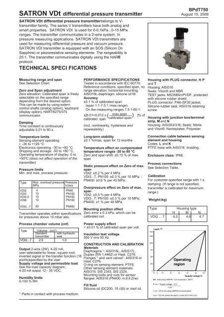
<strong>SATRON</strong> <strong>VDt</strong> <strong>differential</strong> <strong>pressure</strong> <strong>transmitter</strong><strong>SATRON</strong> <strong>VDt</strong> <strong>differential</strong> <strong>pressure</strong> <strong>transmitter</strong> belongs to V-<strong>transmitter</strong> family. The series V <strong>transmitter</strong>s have both analog andsmart properties. <strong>SATRON</strong> <strong>VDt</strong> is used for 0-0,1kPa...0-15 MParanges. The <strong>transmitter</strong> communicates in a 2-wire system. In<strong>pressure</strong> measuring applications <strong>SATRON</strong> <strong>VDt</strong> <strong>transmitter</strong>s areused for measuring <strong>differential</strong> <strong>pressure</strong> and vacuum <strong>pressure</strong>.<strong>SATRON</strong> <strong>VDt</strong> <strong>transmitter</strong> is equipped with an SOS (Silicon OnSapphire) or piezoresistive sensing elemente. The rangeability is25:1. The <strong>transmitter</strong> communicates digitally using the HART®protocol.TECHNICAL SPECI FICATIONSBPdT750August 15, 2009Measuring range and spanSee Selection Chart.Zero and Span adjustmentZero elevation: Calibrated span is freelyselectable on the specified rangedepending from the desired option.This can be made by using externcontrol shafts (analog option), keyboard(display option), HART®275/375communicator.DampingTime constant is continuouslyadjustable 0,01 to 60 s.Temperature limitsSensing element operating:• -30 to +125 °CElectronics operating: -30 to +80 °CShipping and storage: -50 to +80 °C.Operating temperature of display: 0 to+50ºC (does not affect operation of the<strong>transmitter</strong>)Pressure limitsMin. and max. process <strong>pressure</strong>:Type<strong>VDt</strong>2<strong>VDt</strong>3<strong>VDt</strong>4,5<strong>VDt</strong>6<strong>VDt</strong>3...7Max. overload <strong>pressure</strong>,MPa410101040PressurelclassPN40PN100PN100PN100PN400Transmitter operates within specificationsfor <strong>pressure</strong>s above 10 mbar abs.PERFORMANCE SPECIFICATIONSTested in accordance with IEC 60770:Reference conditions, specified span, norange elevation, horizontal mounting;AISI316L-diaphragm, silicone oil fill.Accuracy±0.1 % of calibrated span(span 1:1-7.5:1 /max.range).On the measuring ranges 7.5:1-60:1:±[0.01+0.012 x max.span( ) ]% ofcalibrated span calibrated span(incl. nonlinearity, hysteresis andrepeatability)Long-term stability±0.1 %/max. span for 12 monthsTemperature effect on compensatedtemperature ranges -20 to 80 °CZero and span shift: ±0,15 % of max.spanStatic <strong>pressure</strong> effect on Zero of max.span<strong>VDt</strong>2: ±0.2 % per 4 MPa<strong>VDt</strong>3...7, PN100: ±0.3 % per 10 MPa; ;PN400: ±0.6 % per 40 MPa.Over<strong>pressure</strong> effect on Zero of max.span<strong>VDt</strong>2: ±0,5 % per 4 MPa;<strong>VDt</strong>3...7: PN100: ±0.3 % per 10 MPa;PN400: ±1 % per 40 MPa.Mounting position effectZero error ± 0.3 kPa, which can becalibrated out.Housing with PLUG connector, H, Pand THousing: AISI316Seals: Viton® and NBRTEST jacks: MS358Sn/PVDF, protectedwith silicone rubber shield.PLUG connector: PA6-GF30 jacket,Silicone rubber seal, AISI316 retainingscrew.Housing with junction box/terminalstrip, M and NHousing: AISI303/316; Seals: Nitrileand Viton®; Nameplates: PolyesterConnection cable between sensingelement and housingCodes L and K :PTFE hose with AISI316 braiding.Enclosure class: IP66.Process connectionsSee Selection Table.CalibrationFor customer-specified range with 1 s.damping. (If range is not specified,<strong>transmitter</strong> is calibrated for maximumrange.)Weight (kg)TypeHousing typeH M N<strong>VDt</strong>2 ... 7 4,0 4,6 4,7Process chamber volume (cm 3 )Type Volume (cm 3 )Standard with hydraulic<strong>transmitter</strong> seal<strong>VDt</strong>2...7 2.0 1.0Output 2-wire (2W), 4-20 mA,user selectable for linear, square root,inverted signal or the transfer function (16points)specified by the userSupply voltage and permissible loadSee the load capacity diagram;4-20 mA output: 12 - 35 VDC.Humidity limits0-100 % RH1)Parts in contact with process medium.Power supply effect< ±0.01 % of calibrated span per volt.Insulation test voltage500 V rms 50 HzCONSTRUCTION AND CALIBRATIONMaterialsDiaphragms 1) : AISI316L, AISI317L,Duplex (EN 1.4462) or Hast. C276.Flanges 1) and vent valves 1) : AISI316 orHast. C276.O-ring on sensing element: PTFE.Other sensing element materials:AISI316, SIS 2343, SIS 2324.Mounting bolts and nuts for sensorflanges: AISI316 (PN400: m.8.8.Zne)Fill fluidSilicone oil (DC200, 10 cSt) or inert oil.Load / Ω140012501000750500250Operatingregion010 12 15 20 25 30 35Supply voltage /VMin. load using HART® - communication 250 ΩR max = Supply voltage - 12 VI maxI max = 20.5 mA using HART®-communicationI max = 23 mA (when the alarm current 22,5 mA is on)40
<strong>SATRON</strong> <strong>VDt</strong> <strong>differential</strong> <strong>pressure</strong> <strong>transmitter</strong>Electrical connectionsHousing with PLUG connector, H, P and T :PLUG connector, connector type DIN 43650 model AF; Pg9gland for cable; wire gross-section 0.5 to 1.5 mm 2 .Housing with junction box/terminal strip, M and N:Pg13.5, 1/2-NPT inlet; screw terminals for 0.5 to 2.5 mm 2wiresProduct CertificationsEuropean Directive InformationElectro Magnetic Compatibility(EMC directive 2004/108/EC)All Differential Pressure TransmittersBPdT750August 15, 2009European Pressure Equipment Directive (PED) (97/23/EC)All Differential Pressure Transmitters :Dimensions (in mm)Pg9 std. Housing types H, P and TM20x1,5 std. Housing types M and NØ18.5+0.30Housing types H, T and M 188Housing type N 218Housing type P 26341,3±0,2100Clearace forCoverRemoval1/4-18 NPSFA - A+0.502.514.510012554±0,296AAM10 / deep 14 (PN100)M12 / deep 14 (PN400)7/16-20 UNF / deep 14 (PN400)mAmA-+-+mAS PZ 1Z .5 3Hart®RUN13D DN U P 60Test2-++ - Test11223LoadPowerWiringHousing with PLUG-connector, codes H and TLoadPowerWiringHousing with terminal strip, code M+ - Test LoadPowerWiringHousing with terminal strip, code N
<strong>SATRON</strong> <strong>VDt</strong> <strong>differential</strong> <strong>pressure</strong> <strong>transmitter</strong>BPdT750August 15, 2009100Housing types H, T and M 215Housing type N 245Housing type P 290125170
<strong>SATRON</strong> <strong>VDt</strong> <strong>differential</strong> <strong>pressure</strong> <strong>transmitter</strong>Selection Chart<strong>VDt</strong> Differential Pressure TransmitterBPdT750August 15, 2009Adjustability ( ±)Span, min. Span, max. Measurig range2 0,1 kPa (1 mbar) 6 kPa (60 mbar) -6...+6 kPa (-60...+60 mbar )3 1,4 kPa (14 mbar) 35 kPa (350 mbar) -35 kPa...+35 kPa (-350...+350 mbar)4 4 kPa (40 mbar) 100 kPa (1000 mba) -100...+100 kPa (-1000...+1000 mbar)5 26,5 kPa (265 mbar) 500 kPa (5000 mbar) -500...+500 kPa (-5000...+5000 mbar)6 0,145 MPa (1,45 bar) 3 MPa (30 bar) -3...+3 MPa (-30...+30 bar)7 1 MPa (10 bar) 15 MPa (150 bar ) -15...+15 MPa (-150...+150 bar)OutputS 4-20mA DC/HART® -protocolProcess connectionD M10,PN40 range 2/PN100 ranges 3 to 6,DIN19213 Teil 1. H M12,PN400 ranges 3, 4, 5 and 7,DIN 19213 Teil 2.U 7/16-20 UNF,(PN400 ranges 3, 4, 5 and 7 only).F Screwed flange adapters,PN40 range 2 and PN100ranges 3 to 6,DIN19213 Teil 1; PN250 range 7,DIN19213 Teil 2.Z Welded flange adapters,PN400 ranges 3 to 5 and 7,DIN19213. V Connection through hydraulic seal.Wetted Flanges Diaphragm Diaphragm coatingmaterial Code Material Code MaterialCode Material2 AISI316L 2 AISI316L / AISI317L(specify only when3 Hast.C 276 3 Hast.C 276coated)5 Tantalum9 gold / rhodium8 Duplex (EN 1.4462)Fill fluid S Silicone oil G Inert oilHousing typeH Housing with PLUG-connector, DIN43650, no display, inlet PG9P Housing with PLUG-connector, DIN43650, with display, inlet PG9T Housing with PLUG-connector, DIN43650, no display, inlet PG9, with manual adjustM Housing with junction box/terminal strip, no display, inlet M20x1,5N Housing with junction box/terminal strip, with display, inlet M20x1,5Explosion proof 0 No explosion proof classificationProcess thread Thread type Thread sizeon flange adapter Code Type Code Size(only specify for type F) R straight R thread 2 1/4N NPS thread 3 3/8P taper R thread 4 1/2T NPT threadSpecial size of electrical inletN 1/2 NPT G Pg13.5Special featuresSpecial electronics (specify only if housing connected with hose to sensing element)- connecting cable with protection hoseL Hose protected with PTFE/AISI316 braiding, straightK Hose protected with PTFE/AISI316 braiding, angle of 90 ºLength of cable between sensing element and housing(specify only if housing connected with cable to sensing element)2 2 m cable 3 3 m cable etc. (max. 20 m)Mounting parts for remote electronics for Ø51 mm tube0 No mounting parts 1 Mounting partsDocumentationCalibration CertificateAE EnglishInstallation and Operating Instructions IE English IF FinnishMaterial Certificates0 No material certificateMC1 Raw materials certificate without appendixes, in accordance with SFS-EN 10204-2.1 (DIN 50049-2.1) standardMC2 Raw materials certificate for wetted parts with appendixes, in accordance with SFS-EN 10204-2.2 (DIN 50049-2.2)standardMC3 Raw materials certificate for wetted parts with appendixes, in accordance with SFS-EN 10204-3.1B(DIN 50049-3.1B) standardWe reserve the right for technical modifications without prior notice.HART® is a registered trademark of HART Communication Foundation.Viton® is the registered trademark of DuPont Down Elastomers .Hastelloy® is the registered trademark of Haynes International.Teflon® is the registered trademark of E.I. du Pont de Nemours & Co